3xSLD10U中文资料
敏胶技术有限公司 SIL3 PLe 增量编码器 DSU9H 和 DSU9X 产品说明说明书

|DSU9H & DSU9X MODELSSIL3 PLe INCREMENTAL ENCODERS SPECIFICATIONSFeatures• Usable up to SIL3 and Cat.4 / PLe according to IEC 61508 / EN ISO 13849• Suitable for safe motor feedback according to IEC 61800-5-2• E specially designed for heavy-duty applications (steel, paper, wood, mills, cranes…) Compact and robust design. Excellent resistance to shock and vibration• Stainless steel version available (DSU9X)• 90mm encoder, 30mm standard through shaft, PE E K reduction hub available• High protection level: IP66 (DSU9X), IP65 (DSU9H)• High temperature performance –20°C to +85°C • Power supply 5Vdc or 11/30Vdc• Digital TTL/RS422 or HTL Push-pull or sine/cosine 1Vpp output • Available resolution up to 2048 ppr• Connector or cable output – side orientation• Adapted anti-rotation systemIntroductionApplications• Industrial automation• Automated guided vehicles• Mills for lumber, steel and other metals • Printing and packaging equipment • Food processing equipment• Forming and die pressesDSU9XWhen an automation system requires a high degree of risk mitigation of failure modes, often times Functional Safety equipment can be a part of the solution. Sensata | BEI Sensors offers a wide range of Functional Safety encoders to fit most any application or electrical interface requirement. Rated at SIL3 (PLe), these encoders allow safe operation in set-up, production and maintenance modes, significantly reducing operational risks. All encoders have the option of a Digital HTL or TTL operation as an alternative to the Sine/Cosine outputs found on most Functional Safety encoders. This makes them a compatible replacement for existing encoders when migrating to a higher safety level of operation. DSU9H & DSU9X offer 30 mm standard through shaft models with optional reduction sleeves for mounting on smaller diameter shafts. The encoder body is 90mm in diameter, available in aluminum or stainless steel.(A) Continuous max. speed – ½ max. load – according to ISO 281: 1990, L10(B)Device must be supplied by a Class 2, LPS or SELV limited energy source.(C) UL listed:Electrical ConnectionsNote: All connections are UL certified, except G3 and GP RESOLUTIONS1024 2048DSU9H – radial cable and 20mm reduction hubDSU9X- radial M23 connector - IP66 optionCOUPLING INTERFACE Stator coupling kit M9445/045Tether arm kit M9445/046For a safe installation according to the required safety level needed in the application, refer to the user safety User Manual.The safety User Manual provides the technical information (drawings, electrical data, etc...) for a safe integration.A quick installation guide is provided with each encoder for use by the technician who installs the device on the equipment.GENERAL NOTESORDERING OPTIONSContact the factory for special versions, ex: resolution, connection, flange...* Parts mounted on encoder and fasteners included in the encoder box.AGENCY APPROVALS & CERTIFICATIONSBEI Sensors SASSensata TechnologiesEspace Européen de l’Entreprise9, rue de CopenhagueB.P. 70044 SchiltigheimF 67013 Strasbourg CedexTélFaxMailWeb: +33 (0)3 88 20 80 80: +33 (0)3 88 20 87 87:****************************: Americas+1 (800) 350 2727*******************Europe, Middle East & Africa +33 (3) 88 20 8080****************************Asia Pacific*************************.com China +86 (21) 2306 1500Japan +81 (45) 277 7117Korea +82 (31) 601 2004India +91 (80) 67920890Rest of Asia +886 (2) 27602006 ext 2808Page 7CONTACT USSensata Technologies, Inc. (“Sensata”) data sheets are solely intended to assist designers (“Buyers”) who are developing systems that incorporate Sensata products (also referred to herein as “components”). Buyer understands and agrees that Buyer remains responsible for using its independent analysis, evaluation and judgment in designing Buyer’s systems and products. Sensata data sheets have been created using standard laboratory conditions and engineering practices. Sensata has not conducted any testing other than that specifically described in the published documentation for a particular data sheet. Sensata may make corrections, enhancements, improvements and other changes to its data sheets or components without notice.Buyers are authorized to use Sensata data sheets with the Sensata component(s) identified in each particular data sheet. HOWEVER, NO OTHER LICENSE, EXPRESS OR IMPLIED, BY ESTOPPEL OR OTHERWISE TO ANY OTHER SENSATA INTELLECTUAL PROPERTY RIGHT, AND NO LICENSE TO ANY THIRD PARTY TECHNOLOGY OR INTELLECTUAL PROPERTY RIGHT, IS GRANTED HEREIN. SENSATA DATA SHEETS ARE PROVIDED “AS IS”. SENSATA MAKES NO WARRANTIES OR REPRESENTATIONS WITH REGARD TO THE DATA SHEETS OR USE OF THE DATA SHEETS, EXPRESS, IMPLIED OR STATUTORY, INCLUDING ACCURACY OR COMPLETENESS. SENSATA DISCLAIMS ANY WARRANTY OF TITLE AND ANY IMPLIED WARRANTIES OF MERCHANTABILITY, FITNESS FOR A PARTICULAR PURPOSE, QUIET ENJOYMENT, QUIET POSSESSION, AND NON-INFRINGEMENT OF ANY THIRD PARTY INTELLECTUAL PROPERTY RIGHTS WITH REGARD TO SENSATA DATA SHEETS OR USE THEREOF.All products are sold subject to Sensata’s terms and conditions of sale supplied at SENSATA ASSUMES NO LIABILITY FOR APPLICATIONS ASSISTANCE OR THE DESIGN OF BUYERS’ PRODUCTS. BUYER ACKNOWLEDGES AND AGREES THAT IT IS SOLELY RESPONSIBLE FOR COMPLIANCE WITH ALL LEGAL, REGULATORY AND SAFETY-RELATED REQUIREMENTS CONCERNING ITS PRODUCTS, AND ANY USE OF SENSATA COMPONENTS IN ITS APPLICATIONS, NOTWITHSTANDING ANY APPLICATIONS-RELATED INFORMATION Made in FranceACCESORIES。
UC310串口存储U盘式SD卡模块
/UC310串口存储U盘模块数据手册 v3.0目录一、产品简介 (3)1.1 概述 (3)二、功能介绍 (4)1.1 主要功能 (4)1.2 主要指标 (4)1.3 硬件说明 (4)三、参数配置 (7)1.1 简介 (7)1.2 配置文件说明 (7)四、使用说明 (9)1.1 硬件连接 (9)1.2 SD卡使用 (10)1.3 上传功能 (10)五、使用要点 (10)六、附录(配置文件demo) (11)一、产品简介1.1概述l UC310模块,采用透明传输的方式,将串口送来的数据以文件(FA T32文件系统)形式存储于模块上的SD卡中。
连接USB端口,该模块仿真成U盘,无需任何额外驱动程序,上位机可直接读取文件,也可将SD卡卸下直接由读卡器读出文件。
l UC310模块接口简单,便于连接多种嵌入式及信号采集设备,特别适合需要长期保存海量数据及需要数据交换的应用中。
模块正面模块背面二、功能介绍1.1主要功能采用2线串口,将串口送来的数据透明保存成文件,存储到SD卡上。
n SD卡上使用FAT32文件系统。
n可分割数据保存成多个文件。
n自适应多种容量的SD卡。
n可由USB端口直接读出文件。
n可将SD卡卸下直接由读卡器读出文件。
1.2主要指标电源电压:DC 3.3V ,当成U盘操作时由USB端口直接供电。
温度范围:工业级(-40℃- 70℃),(不含SD卡本身)。
功耗:<45mA( DC3.3V,SD卡操作),<28mA( DC3.3V,待机)。
接口电平:L VTTL或RS232电平可选择。
尺寸:63 * 42.5 * 20 mm(含接插件高度)。
1.3硬件说明1.3.1 机械尺寸图 11.3.2 电气特性表1 电气特性参数符号工作范围单位电源电压VCC +3.0-3.3 V (dc)工作电流I <45 mA输入高电平VIH 0.7*Vcc - Vcc V输入低电平VIL 0-0.3* Vcc V输出高电平VOH Vcc–0.4 -- Vcc V输出低电平VOL 0 - 0.4 V工作温度Ta -40 - 70 ℃表 2 引脚说明名称管脚方向说明nRST 1 IN 复位,低电平有效,不用时可悬空。
STM8S103中文资料

10 电气特性 .................................................................................................................32
10.1 参数条件............................................................................................................................32 10.1.1 最小和最大值 .............................................................................................................32 10.1.2 典型数值 ....................................................................................................................32 10.1.3 典型曲线 ....................................................................................................................32 10.1.4 负载电容 ....................................................................................................................32 10.1.5 引脚输入电压 .............................................................................................................32
星科技 USB 3.0 Mini 多功能适配器用户手册说明书

Quick Start GuideDE: Bedienungsanleitung - FR: Guide de l'utilisateur - ES: Guía del usuario - IT: Guida per l'uso - NL: Gebruiksaanwijzing - PT: Guia do usuário - Manual Revision: 08/29/2014Packaging Contents• 1x USB 3.0 Mini Docking Station • 1x Instruction Manual • 1x Driver CDSystem Requirements• USB enabled computer system with an available USB 3.0 port • Windows® 8 / 8.1 (32/64bit), 7 (32/64), Vista (32/64), XP SP3 (32), Mac OS® 10.6 and up (Tested up to 10.9)• HDMI® or VGA enabled display device if desiredNote: Only a single video output port can be used at one time, HDMI® or VGA. If two displays are connected, the HDMI port will take priority.USB3SMDOCKHVUSB 3.0 Mini Docking Station with HDMI® or VGA, GbE, and USB Pass-throughProduct OverviewFront ViewRear ViewHDMI®Driver InstallationWindows / Mac1. Download the latest drivers from the website (recommended) applicable to your host Operating System that you are connecting to, or, insert the included Driver CD into your computer’s CD/DVD-ROM drive.2. If AutoPlay is enabled, select the “Open folder to view files” option when the dialog appears and run the DisplayLink “.exe” application.3. If AutoPlay is disabled, browse to your CD/DVD drive location (or to where the driver was downloaded) and run the DisplayLink “.exe” application.4. Follow any on-screen instructions to complete the driver installation.Note: You may be prompted to restart your system.InstallationDepending on your Operating System version and whether or not you have an active network connection, the Mini Docking Station may auto-install once connected to an available USB 3.0 port on the host system.If the Mini Docking Station does not auto-install, follow the steps below to complete the Driver Installation process.Hardware Installation1. Connect the Mini Docking Station to an available USB 3.0 port on the computer via the built-in USB Upstream Cable.2. Connect a HDMI® monitor to the HDMI® port on the adapter, or, connect a VGA monitor to the VGA port on the adapter and power on the monitor.Note: Only a single video output can be used at one time, HDMI® or VGA. If a display is connected to each video output port at the same time, then the HDMI® port will take priority.3. Connect your Cat 5e/6 network connection to the RJ-45 port on the adapter if desired4. Connect your USB 3.0 peripheral to the USB 3.0 downstream (USB Pass-through) port on the adapter if desired.Supported Video ResolutionVGA2048x1152Please visit /USB3SMDOCKHV for full operating instructions and installation proceduresFCC Compliance StatementThis equipment has been tested and found to comply with the limits for a Class B digital device, pursuant to part 15 of the FCC Rules. These limits are designed to provide reasonable protection against harmful interference in a residential installation. This equipment generates, uses and can radiate radio frequency energy and, if not installed and used in accordance with the instructions, may cause harmful interference to radio communications. However, there is no guarantee that interference will not occur in a particular installation. If this equipment does cause harmful interference to radio or television reception, which can be determined by turning the equipment off and on, the user is encouraged to try to correct the interference by one or more of the following measures:• Reorient or relocate the receiving antenna.• Increase the separation between the equipment and receiver.• Connect the equipment into an outlet on a circuit different from that to which the receiver is connected.• Consult the dealer or an experienced radio/TV technician for help.Industry Canada StatementThis Class B digital apparatus complies with Canadian ICES-003. Cet appareil numérique de la classe [B] est conforme à la norme NMB-003 du Canada.Digital apparatus (ICES003)CAN ICES-3 (B)/NMB-3(B)Use of Trademarks, Registered Trademarks, and other Protected Names and SymbolsThis manual may make reference to trademarks, registered trademarks, and other protected names and/or symbols of third-party companies not related in any way to . Where they occur these references are for illustrative purposes only and do not represent an endorsement of a product or service by , or an endorsement of the product(s) to which this manual applies by the third-party company in question. Regardless of any direct acknowledgement elsewhere in the body of this document, hereby acknowledges that all trademarks, registered trademarks, service marks, and other protected names and/or symbols contained in this manual and related documents are the property of their respective holders. Technical Support’s lifetime technical support is an integral part of our commitment to provide industry-leading solutions. If you ever need help with your product, visit /support and access our comprehensive selection of online tools, documentation, and downloads.For the latest drivers/software, please visit /downloadsWarranty InformationThis product is backed by a two year warranty.In addition, warrants its products against defects in materials and workmanship for the periods noted, following the initial date of purchase. During this period, the products may be returned for repair, or replacement with equivalent products at our discretion. The warranty covers parts and labor costs only. does not warrant its products from defects or damages arising from misuse, abuse, alteration, or normal wear and tear.Limitation of LiabilityIn no event shall the liability of Ltd. and USA LLP (or their officers, directors, employees or agents) for any damages (whether direct or indirect, special, punitive, incidental, consequential, or otherwise), loss of profits, loss of business, or any pecuniary loss, arising out of or related to the use of the product exceed the actual price paid for the product. Some states do not allow the exclusion or limitation of incidental or consequential damages. If such laws apply, the limitations or exclusions contained in this statement may not apply to you.。
SAM3U中文手册(08-存储系统)

8.存储系统SAM3U 系列8.1片上内嵌存储器8.1.1..1内部SRAMSAM3U4(256KB 内部Flash 版本)内嵌了48KB 的高速SRAM(32KB SRAM0和16KBSRAM1)。
SAM3U2(128KB 内部Flash 版本)内嵌了32KB 的高速SRAM(16KB SRAM0和16KB SRAM1)。
SAM3U1(64KB 内部Flash 版本)内嵌了16KB 的高速SRAM(8KB SRAM0和8KB SRAM1)。
SRAM0从0x20000000地址开始,SRAM1从0x20080000地址开始。
用户所看到的SRAM 是连续的。
SRAM0和SRAM1都在位带区,位带别名区的地址从0x22000000到0x23FF FFFF 。
NAND Flash 控制器内嵌了4224B 的内部SRAM 。
如果NAND Flash 控制器没被使用,那么这4224B 的SRAM 可以作为一般用途,它从地址0x20100000开始。
8.1.1..2内部ROMSAM3U 系列产品内嵌了一个内部ROM ,它包含了SAM-BA 启动程序和FFPI 程序。
任何时候,ROM 区的地址映射都从0x00180000开始。
8.1.3内嵌Flash8.1.3.1Flash 概述SAM3U4(256KB 内部Flash 版本)Flash 的组织形式:两块存储区各512页(双存储平面),每页256字节。
SAM3U2(128KB 内部Flash 版本)Flash 的组织形式:一块存储区有512页(单存储平面),每页256字节。
SAM3U1(64KB 内部Flash 版本)Flash 的组织形式:一块存储区有256页(单存储平面),每页256字节。
Flash 有一个128字节的写缓冲,可通过一个32位接口访问。
8.1.3.2Flash 电源供给Flash 由VDDCORE 供电。
8.1.3.3增强内嵌Flash 控制器增强内嵌Flash 控制器(EEFC)管理系统主控设备的访问操作。
USB3.0中文资料
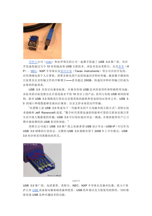
英特尔公司(Intel)和业界领先的公司一起携手组建了USB 3.0推广组,旨在开发速度超过当今10倍的超高效USB互联技术。
该技术是由英特尔,以及惠普(H P)、NEC、NXP半导体以及德州仪器(Texas Instruments)等公司共同开发的,应用领域包括个人计算机、消费及移动类产品的快速同步即时传输。
随着数字媒体的日益普及以及传输文件的不断增大——甚至超过25GB,快速同步即时传输已经成为必要的性能需求。
USB 3.0 具有后向兼容标准,并兼具传统USB技术的易用性和即插即用功能。
该技术的目标是推出比目前连接水平快10倍以上的产品,采用与有线USB相同的架构。
除对USB 3.0规格进行优化以实现更低的能耗和更高的协议效率之外,USB 3.0 的端口和线缆能够实现向后兼容,以及支持未来的光纤传输。
“从逻辑上说USB 3.0将成为下一代最普及的个人电脑有线互联方式”,英特尔技术战略师Jeff Ravencraft说道,“数字时代需要高速的性能和可靠的互联来实现日常生活中庞大数据量的传输。
USB 3.0可以很好地应对这一挑战,并继续提供用户已习惯并继续期待的USB易用性体验。
”英特尔公司成立USB 3.0推广组之初就希望USB设计学会(USB-IF)可以作为USB 3.0规格的行业协会。
完整的USB 3.0规格有望于2008年上半年推出,USB 3.0初步将采用离散硅的形式。
usb3.0USB 3.0推广组,包括惠普、英特尔、NEC、NXP半导体以及德州仪器,致力于保护已有USB设备驱动器基础设施和投资、USB的外观以及方便使用的特性,同时继续发扬USB这种卓越技术的功能。
“我们对USB 2.0以及无线USB技术的支持彰显了惠普致力于为客户提供可靠的外围设备互联方式”,惠普公司负责打印成像与消费市场部门(Consumer Inkjet Solutions)的副总裁Phil Schultz说,“现在借助USB 3.0,我们将为客户创造打印机、数码相机及其他外围设备与个人电脑互联的更佳体验。
星技FCREADMICRO3 USB3.0多媒体卡读写器(SDHC MicroSD产品ID)说明书

USB 3.0 External Flash Multi Media Memory Card Reader - SDHC MicroSDProduct ID: FCREADMICRO3The FCREADMICRO3 USB 3.0 Multi-media Card Reader offers quick access to the most popular flash card formats, from any computer with a USB port (optimal performance with 3.0, backward compatible with USB 2.0).Suitable for quickly accessing memory cards of virtually any portable media device (e.g. digital cameras, MP3 players, etc.), this versatile media card reader supports the most popular card types, including:•Secure Digital (SD)•Multi-Media Card (MMC)•Mini-SD, Micro-SD/SDHC (T-flash)•SDHC•SDXC•RS-MMC•Mobile-MMC and MMC-micro•Memory Stick (MS)•Memory Stick PRO (MS-PRO)•MS DuoMS-PRO Duo•MS-PRO Duo•Memory Stick XC•Micro-MS (M2)•MSPRO-HG Duo 8-bit mode.An ideal Laptop or Desktop accessory, this pocket-sized memory card reader is lightweight, portable, and backed by a 2-year warranty with free lifetime technical support.Certifications, Reports and Compatibility Applications•Mobile users/travelers who need a compact and lightweight cardreader small enough to fit in a pocket•Photographers who need to regularly transfer files from their camera memory card to a computer•Transferring files to and from a variety of portable devices, each using a different memory card formatFeatures•High Speed USB 3.0 host interface with support for transfer rates upto 5 Gbps•Support for Secure Digital (SD), MultiMedia Card (MMC), Mini-SD,Micro-SD/SDHC (T-flash), SDHC, SDXC, RS-MMC, Mobile-MMC andMMC-micro, Memory Stick (MS), Memory Stick PRO (MS-PRO), MSDuo, MS-PRO Duo, Memory Stick XC, Micro-MS (M2), and MSPRO-HGDuo 8-bit mode•Ultra-compact and lightweight design•Powered directly from the USB port•Plug-and-Play and Hot-Swap compatibleWarranty 2 YearsHardware Bus Type USB 3.0Chipset ID Realtek - RTS5307Interface USB 3.0Performance Maximum Data Transfer Rate 5 Gbit/sMemory Media Type HS-MMC, HC-MMC (High Speed/High Capacity MultimediaCard)M2 (Memory Stick Micro)Memory StickmicroSDHC (Micro Secure Digital High Capacity)MS Duo, MS Pro Duo, MS Pro-HG DuoMS Micro (Memory Stick Micro)MSXC (Memory Stick eXtended Capacity)Multi Media CardRS-MMC (Reduced Size Multimedia Card)SD/MMC (Secure Digital/Multimedia Card)SDHC (Secure Digital High Capacity)SDXC (Secure Digital eXtended Capacity)Connector(s)Connector Type(s) 1 - USB Type-A (9 pin) USB 3.0 MaleExternal Ports 1 - Memory Stick / Memory Stick Pro Slot Female1 - MicroSD Female1 - SD / MMC Slot FemaleSoftware OS Compatibility OS independent; No software or drivers requiredPower Power Source USB-PoweredEnvironmental Humidity< 80% R.H.Operating Temperature0°C to 40°C (32°F to 104°F)Storage Temperature-20°C to 60°C (-4°F to 140°F)Color BlackPhysicalCharacteristicsMaterial PlasticProduct Height0.6 in [1.5 cm]Product Length 2.8 in [72 mm]Product Width0.9 in [23 mm]Weight of Product0.5 oz [15 g]Package Height 1.3 in [32 mm]PackagingInformationPackage Length 6.9 in [17.5 cm]Package Width 5.6 in [14.2 cm]Shipping (Package) Weight 3.7 oz [104 g]What's in the Box Included in Package 1 - USB 3.0 Multi Media Memory Card Reader Adapter1 - Instruction ManualProduct appearance and specifications are subject to change without notice.。
D103中文资料
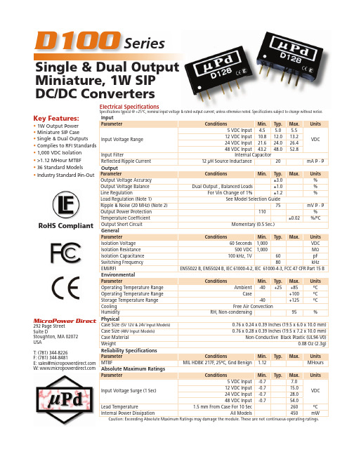
Key Features:• 1W Output Power • Miniature SIP Case • Single & Dual Outputs • Complies to RFI Standards • 1,000 VDC Isolation • >1.12 MHour MTBF • 36 Standard Models•Industry Standard Pin-OutD100Single & Dual Output Miniature, 1W SIP DC/DC Con v ert e rsSeriesMicroPower Direct 292 Page Street Suite DStoughton, MA 02072USAT: (781) 344-8226F: (781) 344-8481E: sales@ W: RoHS CompliantElectrical Specifi cationsSpecifi cations typical @ +25°C, nominal input voltage & rated output current, unless otherwise noted. Specifi cations subject to change without notice.• All dimensions are typical in inches (mm) Tolerance x.xx = ±0.01 (±0.25)• Pin 1 is marked by a “dot” or indentation onthe side of the unitNotes:1. Output load regulation is specifi ed for a load change of 20% to 100%.2. T hese units do not require external components to operate, but the use of an input capacitor (10 μF) may enhance performance in some applications. It is recommended that an input capacitor of 4.7 u F to 47 u F (dependent upon the application) be used on 48V input model.An output capacitor (4.7 μF to 100 μF or ±4.7 μF to ±68 μF) may be used to reduce ripple. To improve EMI performance, a simple fi lter network consisting of a 10 u F to 100 u F capacitor and 12 u H inductor should be effective.3. These units will operate at no load without damage, but may not meet all specifi cations.4. D ual output units may be connected to provide a 10V, 18V, 24V or 30 VDC output. To do this, connect the load across the positive (+Vout) and negative (-Vout) outputs and fl oat the output common.5. It is recommended that a fuse be used on the input of a power supply for protection. See the table above for the correct rating.Derating CurveNotes:All dimens•Tolerance Pin 1 is mathe side ofMicroPower Direct292 Page Street, STE D, Stoughton, MA 02072 • TEL: (781) 344-8226 • FAX: (781) 344-8481 • E-Mail: sales@Model Selection GuideMechanical DimensionsCapacitive Other input/output combinations are available(i.e. 24.0 VDC). Contact the factory for details at:sales@。
- 1、下载文档前请自行甄别文档内容的完整性,平台不提供额外的编辑、内容补充、找答案等附加服务。
- 2、"仅部分预览"的文档,不可在线预览部分如存在完整性等问题,可反馈申请退款(可完整预览的文档不适用该条件!)。
- 3、如文档侵犯您的权益,请联系客服反馈,我们会尽快为您处理(人工客服工作时间:9:00-18:30)。
All products are sold to the commercial specifications shown, for any additional reliability testing or extended parameters, please consult the factory.
contact semitron on: telephone: +44 (0)1793 724000fax: +44 (0)1793 720401
APPLICATION
•Designed to protect sensitive electronics which operate within an
automotive system, such as: Sound systems, satellite navigation, climate control, engine management, stability control, ABS etc.
DESCRIPTION
The SLD series is specifically designed for automotive applications, available in both unidirectional and bidirectional.
The SLD 10U is designed to be used in series, for example three 10U’s in series for a 30 volt
working; this configuration will provide a very high power (a multiple of 3) capability and is a far superior solution than using devices in parallel, which will require closely matched devices in order to prevent ‘current hogging’ and consequently, damage to the device.
All dimensions in mm.
FEATURES
•2200 Watts Peak Power rated with 100µS/150mS pulse (applies to a single device)
•50,000 Watts Peak Pulse Power based on 8/20µS (applies to a single device)•UL 94V-0 Flammability Classification
HIGH POWER AUTOMOTIVE TRANSIENT VOLTAGE SUPPRESSORS FOR PROTECTION AGAINST LOAD DUMP CONDITIONS.Note 1. Mounted on copper pad area 40mm square
Note 2. Using 300 microsecond square pulse; applies to unidirectional only, and a single device only.For devices used in series, this value should be multiplied by the number of devices.
Note 3. 100µS / 150mS pulse as defined by ISO7637/2 pulse # 5Please note, U suffix denotes unidirectional
SLDSeries
SLD Series
8.0Characteristics @ 25˚C case temp (unless otherwise noted)
ABSOLUTE MAXIMUM RATINGS @ 25˚C case temp (unless otherwise noted)。