Hurricane_SOP_TAB_0412_v4
速维达 Selontra 安全技术说明书
安全技术说明书页: 1/12 巴斯夫安全技术说明书按照GB/T 16483编制日期 / 本次修订: 05.09.2021版本: 2.0日期/上次修订: 18.06.2021上次版本: 1.1日期 / 首次编制: 11.08.2020产品: 速维达 Selontra®Product: Selontra(30662329/SDS_GEN_CN/ZH)印刷日期 01.11.20231. 化学品及企业标识速维达 Selontra®Selontra推荐用途和限制用途: 灭鼠剂, 杀生制品公司:巴斯夫(中国)有限公司中国上海浦东江心沙路300号邮政编码 200137电话: +86 21 20391000传真号: +86 21 20394800E-mail地址: **********************紧急联络信息:巴斯夫紧急热线中心(中国)+86 21 5861-1199巴斯夫紧急热线中心(国际):电话: +49 180 2273-112Company:BASF (China) Co., Ltd.300 Jiang Xin Sha RoadPu Dong Shanghai 200137, CHINA Telephone: +86 21 20391000Telefax number: +86 21 20394800E-mail address: ********************** Emergency information:Emergency Call Center (China):+86 21 5861-1199International emergency number: Telephone: +49 180 2273-1122. 危险性概述纯物质和混合物的分类:根据 GHS 标准,该产品不需要进行分类。
巴斯夫安全技术说明书日期 / 本次修订: 05.09.2021版本: 2.0产品: 速维达 Selontra®Product: Selontra(30662329/SDS_GEN_CN/ZH)印刷日期 01.11.2023标签要素和警示性说明:防范说明:P101如需就医:请随身携带产品容器或标签。
Hurricane Haze 4D 用户手册说明书
User ManualT ABLE OF C ONTENTS1. Before You Begin (1)What Is Included (1)Unpacking Instructions (1)Claims (1)Text Conventions (1)Symbols (1)Disclaimer (1)Product at a Glance (2)Safety Notes (2)2. Introduction (3)Product Overview (3)Product Dimensions (3)3. Setup (4)AC Power (4)Fuse Replacement (4)Mounting (5)Orientation (5)Rigging (5)4. Operation (6)Hurricane Haze 4D Control Priority (6)Control Panel Operation (6)Manual Control Knobs (6)Menu Map (6)Configuration (DMX) (6)Starting Address (6)DMX Channel Assignments and Values (6)Wired Timer Remote Setup (7)Wired Timer Remote Operation (7)5. Maintenance and Storage (8)Hazer Maintenance (8)Storage (8)6. Technical Specifications (9)7. Returns (10)7. Contact Us (11)1. B EFORE Y OU B EGINWhat Is IncludedUnpacking InstructionsCarefully unpack the product immediately and check the container to make sure all the parts are in the package and are in good condition.ClaimsIf the box or the contents (the product and included accessories) appear damaged from shipping, or show signs of mishandling, notify the carrier immediately, not Chauvet. Failure to report damage to the carrier immediately may invalidate your claim. In addition, keep the box and contents for inspection.For other issues, such as missing components or parts, damage not related to shipping, or concealed damage, file a claim with Chauvet within 7 days of delivery.Text ConventionsSymbolsDisclaimerChauvet believes that the information contained in this manual is accurate in all respects. However,Chauvet assumes no responsibility and specifically disclaims any and all liability to any party for any loss, damage or disruption caused by any errors or omissions in this document, whether such errors oromissions result from negligence, accident or any other cause. Chauvet reserves the right to revise the content of this document without any obligation to notify any person or company of such revision, however, Chauvet has no obligation to make, and does not commit to make, any such revisions. Download the latest version from .The works of authorship contained in this manual, including, but not limited to, all design, text and images are owned by Chauvet.© Copyright 2016 Chauvet & Sons, LLC. All rights reserved.Electronically published by Chauvet in the United States of America.CHAUVET, the Chauvet logo, and Hurricane Haze 4D are registered trademarks or trademarks of Chauvet & Sons LLC (d/b/a Chauvet and Chauvet Lighting) in the United States and other countries. Other company and product names and logos referred to herein may be trademarks of their respective companies.•Hurricane Haze 4D •Power Cord•Wired Timer Remote•Hanging Bracket with Mounting Hardware •Warranty Card•Quick Reference GuideProduct at a Glance•Not intended for permanent installations.•Always connect the product to a grounded circuit to avoid the risk of electrocution.•Always disconnect this product from the power source before cleaning it or replacing the fuse.•Make sure the power cord is not crimped or damaged.•Never disconnect the power cord by pulling or tugging on the cord.•If mounting this product overhead, always secure it to a fastening device using a safety cable.•Do not mount this product on a flammable surface (e.g., wood, linoleum, carton, plastic, or carpet).•Make sure there are no flammable materials close to the unit while operating•Do not touch the output nozzle on this product. It is very hot during operation and it may remain hot for several hours after turning the unit off.•Do not drink the haze fluid. If you do, call your local emergency service (911 in the US) for help.•Do not add perfume, alcohol, gasoline, or any other flammables to the haze fluid.•Depending on the amount of haze generated, all haze machines may set off smoke detectors.•In certain environments, haze fluid-based machines may leave a slippery residue on floors and surfaces.•Do not use for space heating purposes.•Use only CHAUVET DJ water-based haze fluid.•Drain the tank before transporting the product.•Always make sure that the voltage of the outlet to which you are connecting the product is within the range stated in the decal or rear panel of the product.•This product is for indoor use only! To prevent risk of fire or shock, do not expose this product to rain or moisture.•Always install this product in a location with adequate ventilation, at least 20 in (50 cm) from adjacent surfaces.•Be sure that no ventilation slots on the unit’s housing are blocked.•Never connect this product to a dimmer or rheostat.•Make sure to replace the fuse with another of the same type and rating.•Never carry the product from the power cord or any moving part. Always use the hanging/ mounting bracket.•The maximum ambient temperature (Ta) is 104 °F (40 °C). Do not operate this product at higher temperatures.•In the event of a serious operating problem, stop using the product immediately.•Never try to repair this product. Repairs carried out by unskilled people can lead to damage or malfunction. Please contact the nearest authorized technical assistance center.•To eliminate unnecessary wear and improve its lifespan, during periods of non-use completely disconnect the product from power via breaker or by unplugging it.Keep this User Manual for future use. If you sell the product, be sure that the purchaser receives this document.2. I NTRODUCTIONProduct OverviewProduct DimensionsFluid TankBlower FanDMX In/OutHaze Output KnobRemote InPower SwitchPower In Fuse HolderFan Speed KnobMenu ButtonsLED Display3. S ETUPAC PowerThe Hurricane Haze 4D has a fixed voltage power supply and it can work with an input voltage of either 120 VAC, 60 Hz or 230 VAC, 50 Hz, depending on the specific model.To determine the product’s power requirements (circuit breaker, power outlet, and wiring), use the current value listed on the label affixed to the product’s back panel, or refer to the product’s specifications chart. The listed current rating indicates the product’s average current draw under normal conditions.Fuse Replacement1.Wedge the tip of a flat-head screwdriver into the slot of the fuse holder.2.Pry the fuse holder out of the housing.3.Remove the blown fuse from the holder and replace with a fuse of the exact same type and rating.4.Insert the fuse holder back in place and reconnect power.•Always connect the product to a protected circuit (a circuit breaker or fuse).Make sure the product has an appropriate electrical ground to avoid the risk of electrocution or fire.•To eliminate unnecessary wear and improve its lifespan, during periods of non-use completely disconnect the product from power via breaker or by unplugging it.Never connect the product to a rheostat (variable resistor) or dimmer circuit, even if the rheostat or dimmer channel serves only as a 0 to 100% switch.Disconnect the product from the power outlet before replacing the fuse.Safety capSpare fuse holder(inside safety cap)Installed fuse(held by plastic clip)MountingBefore mounting the product, read and follow the safety recommendations indicated in the Safety Notes .OrientationRigging•Before deciding on a location, always make sure there is easy access to the product for maintenance and fluid replenishment.•Make sure adequate ventilation is provided around the product.•Make sure that the structure or surface onto which you are mounting the product can support the product’s weight. (see the Technical Specifications )•When mounting the product overhead, always use a safety cable. Mount the product securely to a rigging point, such as an elevated platform or a truss.•When rigging the product onto a truss, you should use a mounting clamp of appropriate weight capacity. The bracket has 13-mm holes, which are appropriate for this purpose.•The rubber feet also serve as floor supports and allow for surface mounting. When mounting the product on the floor, make sure that the product and cables are away from people and vehicles.Mounting DiagramThis product may NOT be tilted. This product should be level when on a surface or when mounted.While operating the Hurricane Haze 4D, make sure there is adequate haze fluid in the machine to prevent pump and heater damage. When the haze fluid levelbecomes low, simply add more haze fluid to continue using the Hurricane Haze 4D.Mounting BracketSafety Cable(such as CH-05 fromChauvet)Mounting Clamp(such as CLP-15 or CLP-15Nfrom Chauvet)BracketAdjustable ScoopFluid Level IndicatorRubber Feet for Floor Mounting(x4)4. O PERATIONHurricane Haze 4D Control PriorityThe Hurricane Haze 4D operates according to the following priority control levels:Control Panel OperationTo access the control panel functions, use the four buttons located underneath the display, and the two manual control knobs located to the right of the display. Please refer to the Product Overview to see the button and knob locations on the control panel.Manual Control KnobsThe manual control knobs allow for operation of the Hurricane Haze 4D without a controller.Configuration (DMX)The Hurricane Haze 4D works with a DMX controller. Information about DMX is in the CHAUVET DMX Primer, which is available from the Chauvet website/downloads/DMX_Primer_rev05_WO.pdf .Starting AddressWhen selecting a starting DMX address, always consider the number of DMX channels the selected DMX mode uses. If you choose a starting address that is too high, you could restrict the access to some of the product’s channels.The Hurricane Haze 4D uses 2 DMX channels, which defines the highest configurable address to 511.If you are not familiar with the DMX protocol, download the DMX Primer from .To select the starting address, do the following:1.Press <MENU> repeatedly until d _ _ _shows on the display.e <UP> or <DOWN> to select the starting address.3.Press <ENTER>.DMX Channel Assignments and Values1. A DMX controller takes the highest priority, and will override both the Wired TimerRemote and the manual control knobs.2.The manual control knobs will override the Wired Timer Remote, but not a DMXcontroller.3.The Wired Timer Remote has the lowest priority.Wired Timer Remote SetupThe Wired Timer Remote allows you to automatically trigger haze output by setting output, interval time, and duration time. LED indicator lights display the machine and controller’s current state. Rotary knobs set interval, output, and duration times, while manual and continuous buttons allow overriding control.1.Plug in the haze machine to power.2.Plug in the wired timer controller to the Remote socket on the back of the haze machine. (See theProduct Overview .)3.Allow the Hurricane Haze 4D three to four minutes to heat up before continuing.Wired Timer Remote OverviewWired Timer Remote OperationThe Wired Timer Remote has three modes of operation: timer, continuous, and manual.Timer ModeTo trigger the Hurricane Haze 4D with the timer function, follow the instructions below:1.Set the desired output level with the OUTPUT knob.2.Set the INTERVAL and DURATION knobs to the desired positions.•The INTERVAL knob sets the amount of time in between bursts of haze.•The DURATION knob sets the length of time that the haze machine will run during the burst.3.Press the <TIMER ON/OFF> latching button. The LED indicator above the button will light up.The timer will now run as set by the INTERVAL , DURATION , and OUTPUT knobs.4.Press the <TIMER ON/OFF> button again to turn off the timer.Continuous ModeTo trigger the Hurricane Haze 4D to continuously cycle haze, follow the instructions below:1.Set the desired output level with the OUTPUT knob.2.Press the <CONTINUOUS> latching button. The LED indicator above the button will light up. Thehaze machine outputs haze until the <CONTINUOUS> button is pressed again.3.Press the <CONTINUOUS> button again to stop the haze output.Manual ModeTo trigger the Hurricane Haze 4D manually, do the following:1.Set the desired output level with the OUTPUT knob.2.Press and hold the <MANUAL> button on the Wired Timer Remote. The LED indicator above thebutton will light up. The haze machine will output haze for as long as you hold down the <MANUAL> button.3.Release the <MANUAL> button to stop the haze output.The MANUAL Button will override the timer function.•The duration of Continuous haze output is based on the capacity of the tank.•Fluid consumption will be significantly increased during Continuous mode.INTERVAL KnobOUTPUT Knob TIMER ON/OFF Button DURATION KnobMANUAL ButtonCONTINUOUS Button5. M AINTENANCE AND S TORAGEHazer MaintenanceDo not allow the hazer to become clogged. After every 40 hours of continuous operation, use CHAUVET Fog Cleaner Quart (FCQ) through the system to prevent the accumulation of particulate matter in the heating element.The recommended cleaning procedure is as follows.1.Unplug the product from power.2.Empty all haze fluid from the machine.3.Add cleaning solution to the tank.4.Connect the product to power and allow it to warm up.5.Run the unit in a well-ventilated area until the tank is almost empty. Do not allow the pump to rundry.6.Refill with haze fluid to continue using the hazer. Run the machine briefly to clear any remainingcleaning solution from the pump and heater.StorageBefore storing the hazer, run FCQ through the system as described in the cleaning procedure above; however, only follow steps 1 through 5. Do not refill the tank with haze fluid if storing the hazer . Cleaning the system prior to storage will help prevent any particles from condensing inside the pump or heater while not in use.Powering off the unit for transportFollow these instructions to prevent leaks, and allow the air pump to entirely clear the fluid line and heater of the haze fluid before power off.Do Not operate the machine without fluid at any time.Fog Cleaner Quart (FCQ) was specifically developed by Chauvet to clean your Hurricane Haze 4D. Make sure you use FCQ regularly, no longer than 90 days between cleanings, to increase the life of your product.Test-run your Hurricane Haze 4D on a monthly basis to achieve the best performance.To prevent spills or leaks before, during, or after transport, Chauvet recommends the following steps for your Hurricane Haze 4D:1.Turn the "Haze Volume " output to off.2.Wait 30-45 seconds.3.When there is no more haze fluid in the output line, turn off the machine by pressingthe power switch.6. T ECHNICAL S PECIFICATIONSDimensions and WeightNote : Dimensions in inches rounded to the nearest decimal digit.PowerOperationFog OutputThermalDMXOrderingL ENGTHW IDTHH EIGHTW EIGHT 11 in (277 mm)15.5 in (396 mm)9.6 in (245 mm)13.2 lb (6 kg)P OWER S UPPLY T YPER ANGEV OLTAGE S ELECTIONModel-specific 120 VAC, 60 Hz, or 230 VAC, 50 HzFixed P ARAMETER 120 V, 60 H Z 230 V, 50 H Z Consumption 1120 W 1120 W Operating Current8.1 A 4.8 A Fuse F 15 A, 250 V F 15 A, 250 V P OWER I/OU.S./W ORLDWIDEUK/E UROPEPower input connector IECIEC Power Cord plugEdison (U.S.)Local Plug H EAT -U P T IMET ANK C APACITY F LUID C ONSUMPTION2 min9 gal (3.75 l)10 ml/minO UTPUT 4300 cfmM AXIMUM E XTERNAL T EMPERATUREC OOLING S YSTEM104 °F (40 °C)Convection I/O C ONNECTORC HANNEL R ANGE3-pin XLR2P RODUCT N AMEITEM CODE UPC N UMBER Hurricane Haze 4D (120 V)05071211781462215590Hurricane Haze 4D (230 V)05071212781462215606R ETURNSIn case you need to get support or return a product:•If you are located in the U.S., contact Chauvet World Headquarters.•If you are located in the UK or Ireland, contact Chauvet Europe Ltd.•If you are located in Mexico, contact Chauvet Mexico.•If you are located in Benelux, contact Chauvet Europe BVBA.•If you are located in any other country, DO NOT contact Chauvet. Instead, contact your localdistributor. See for distributors outside the U.S., UK, Ireland, Mexico, or Benelux.Call the corresponding Chauvet Technical Support office and request a Return Merchandise Authorization (RMA) number before shipping the product. Be prepared to provide the model number, serial number, and a brief description of the cause for the return.Send the merchandise prepaid, in its original box, and with its original packing and accessories. Chauvet will not issue call tags.Clearly label the package with the RMA number. Chauvet will refuse any product returned without an RMA number.Before sending the product, clearly write the following information on a piece of paper and place it inside the box:•Your name •Your address •Your phone number •RMA number • A brief description of the problemBe sure to pack the product properly. Any shipping damage resulting from inadequate packaging will be your responsibility. FedEx packing or double-boxing are recommended.If you are located outside the U.S., UK, Ireland, Mexico, or Benelux, contact yourdistributor of record and follow their instructions on how to return Chauvet products to them. Visit our website for contact details.Write the RMA number on a properly affixed label. DO NOT write the RMA number directly on the box.Chauvet reserves the right to use its own discretion to repair or replace returnedproduct(s).C ONTACT U SVisit the applicable website above to verify our contact details and instructions to request support.Outside the U.S., United Kingdom, Ireland, Mexico or Benelux, contact the dealer of record.Sunrise, FL 33351Fax: (954) 756-8015Voice: (954) 577-4455Email: ************************Fax: (954) 929-5560Toll Free: (800) 762-1084Email: *************************9770 KruishoutemBelgiumwww.chauvetlighting.euVoice: +32 9 388 93 97Email: **************************Brookhill Road Industrial EstatePinxton, Nottingham, UKNG16 6NTVoice: +44 (0) 1773 511115Fax: +44 (0) 1773 511110Industrial LermaEmail: ********************.mxLerma, Mexico C.P . 52000Voice: +52 (728) 285-5000.mx。
枫叶报警主机Sp系列简易编程
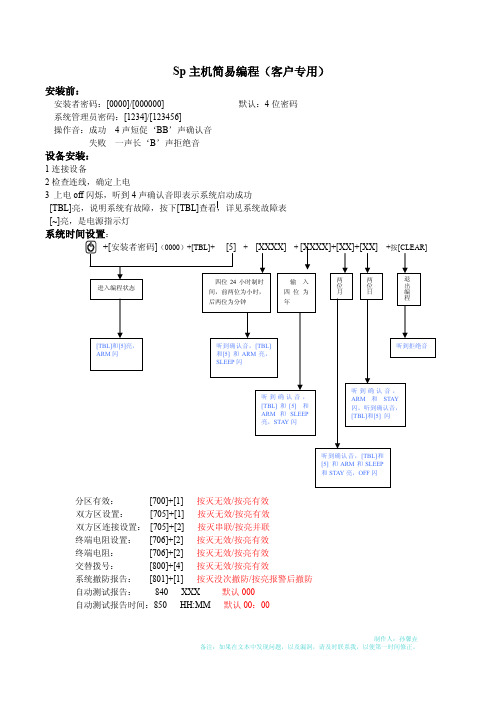
Sp主机简易编程(客户专用)安装前:安装者密码:[0000]/[000000] 默认:4位密码系统管理员密码:[1234]/[123456]操作音:成功4声短促‘BB’声确认音失败一声长‘B’声拒绝音设备安装:1连接设备2检查连线,确定上电3 上电off闪烁,听到4声确认音即表示系统启动成功[TBL]亮,说明系统有故障,按下[TBL]查看,详见系统故障表[~]亮,是电源指示灯系统时间设置:分区有效:[700]+[1] 按灭无效/按亮有效双方区设置:[705]+[1] 按灭无效/按亮有效双方区连接设置:[705]+[2] 按灭串联/按亮并联终端电阻设置:[706]+[2] 按灭无效/按亮有效终端电阻:[706]+[2] 按灭无效/按亮有效交替拨号:[800]+[4] 按灭无效/按亮有效系统撤防报告:[801]+[1] 按灭没次撤防/按亮报警后撤防自动测试报告:840 XXX 默认000自动测试报告时间:850 HH:MM 默认00:002 编程:(所有防区如果不设置均无效)例:防区1 设置为立即防区,属于分区1,防区可自动关闭,可旁路,可RF监测有声报警编程:[ENTER]+[0000]+[001]+[08]+[1]+按亮[1].[2].[3].[8]无线防区编程:段号:[061]~[092]对应01~32防区无线设备序列号无线防区编程防区属性定义在有线防区定义,如果同一防区如果设为无线防区,则有线防区无效延时设置:按[XXX] +按[CLEAR]中心拨号设置:按+安装者密码(0000)+ [X] +个人拨号设置:按+安装者密码(0000)遥控器编程:[651]~[682]对应32个遥控器ENTER +密码:1 用户密码创建 01~32对应32个用户,01为系统管理员密码主板复位: 按住[RESET]开关5S ,STATUS 灯闪烁2S ,在按[RESET]开关2S ,听到确认音,复位成功。
常规操作:1 布防按[ARM]/[STAY]/[SLEEP]+系统密码/用户密码2 撤防按[OFF]+系统密码/用户密码备注: [XXX]为输入数据,红色字体为输入数据含义及说明 兰色字体为键盘与声音现象户号亮SLEEP 应用户号和和SLEEP 下一个灯闪,闪闪,亮,对应用户号亮ARM 亮,应用户号亮闪,。
WinDbg用户指南说明书

Table of ContentsAbout1 Chapter 1: Getting started with WinDbg2 Remarks2 Versions2 Examples2 Installation or Setup2 Debuggers3 Chapter 2: Crash analysis4 Examples4 Basic user mode crash analysis4 Chapter 3: DML(Debugger Mark Language)5 Examples5 Turn on/off5 Chapter 4: Extensions6 Examples6 SOS6 SOSex6 PyKD6 Getting started with PyKd6 NetExt7 Extensions overview7 CoSOS7 Chapter 5: Kernel debugging9 Examples9 Important commands9 Chapter 6: Remote debugging10 Examples10 Important commands10 Chapter 7: User mode / application debugging11 Examples11Important commands11 Documenting your work11 Working with symbols11 Crash analysis12 The environment12 Threads, call stacks, registers and memory12 Controlling the target13 Working with extensions13 Stop debugging13 Attach and detach14 Behavior of WinDbg14 Usability Commands14 Getting Helps14 Create Custom Command Window in Windbg14 Credits16AboutYou can share this PDF with anyone you feel could benefit from it, downloaded the latest version from: windbgIt is an unofficial and free WinDbg ebook created for educational purposes. All the content is extracted from Stack Overflow Documentation, which is written by many hardworking individuals at Stack Overflow. It is neither affiliated with Stack Overflow nor official WinDbg.The content is released under Creative Commons BY-SA, and the list of contributors to each chapter are provided in the credits section at the end of this book. Images may be copyright of their respective owners unless otherwise specified. All trademarks and registered trademarks are the property of their respective company owners.Use the content presented in this book at your own risk; it is not guaranteed to be correct nor accurate, please send your feedback and corrections to ********************Chapter 1: Getting started with WinDbg RemarksThis section provides an overview of what windbg is, and why a developer might want to use it.It should also mention any large subjects within windbg, and link out to the related topics. Since the Documentation for windbg is new, you may need to create initial versions of those related topics.VersionsImportant versions of WinDbg, for supported versions of WinDbg. See also a detailed list with historical versions online.It's important to note that there's a versioning scheme change from older 6.12 to the newer 6.1 version. The older versions have low numbers (<100) in the third place while newer versions have high numbers (>6000).In many cases, WinDbg versions provided for newer Windows versions still work on older versions on Windows, e.g. Version 10 of WinDbg can still be used on Windows 7. However, some commands may make use of API calls that are not available and thus fail. Therefore it's good to have several versions of WinDbg available.ExamplesInstallation or SetupMicrosoft describes 3 ways of installing WinDbg:•as part of the WDK (Windows Driver Kit)•as part of the SDK (Software Development Kit)with the installer of the SDK and deselecting everything else but "Debugging Tools for•Windows"To get the installer, visit Download the WDK, WinDbg, and associated tools and scroll down to a section called "Get debugging tools".A well-known and convenient but inofficial source is Codemachine where you can also download older versions of the Debugging Tools directly.The setup itself is straight-forward. Click through the installer until it finishes.DebuggersWinDbg is often used as an abbreviation of "Debugging tools for Windows". It contains different debuggers:The commands are identical, except that there may be GUI related commands which don't work in the console versions.Read Getting started with WinDbg online: https:///windbg/topic/1833/getting-started-with-windbgChapter 2: Crash analysisExamplesBasic user mode crash analysis.exr -1 gives you details about the last exception thrown.!analyze -v usually does a good job as well.For .NET, the command !pe of the SOS extension shows details about the .NET exception that was thrown.Read Crash analysis online: https:///windbg/topic/5389/crash-analysisChapter 3: DML(Debugger Mark Language) ExamplesTurn on/off.prefer_dml 1 turn on dmlformat output.prefer_dml 0 turn off dmlformat outputRead DML(Debugger Mark Language) online: https:///windbg/topic/7987/dml-debugger-mark-language-Chapter 4: ExtensionsExamplesSOSSOS (son of strike) is the official WinDbg extension from Microsoft for .NET. It gets installed as part of the .NET framework and thus is available by default.Like any extension, it can be loaded using .load x:\full\path\to\sos.dll, but there are easier ways. Depending on the version of .NET, the extension is located side by side to mscorwks.dll(.NET CLR 2), clr.dll (.NET CLR 4) or coreclr.dll (Silverlight and Universal apps), so one of the following commands should work:.loadby sos clr.loadby sos coreclr.loadby sos mscorwksFor a list of available commands, consult !help.SOSexSOSex is an extension to SOS, written by Steve Johnson, a Microsoft employee. He provides SOSex for download for free, but it's not open source.Typically, the extension is not available side by side to any other DLL, so it is usually loaded with .load x:\full\path\to\sosex.dll.Besides simplifying debugging of .NET, the command !dlk can also be used in native environments for checking deadlocks of critical sections.For a list of available commands, consult !help of SOSex.PyKDPyKD is a WinDbg extension that enables you writing Python scripts. It's open source.Typically, the extension is not available side by side to any other DLL, so it is usually loaded with .load x:\full\path\to\pykd.pyd, where PYD is the extension for a python DLL, but you can rename it to DLL if you like.Getting started with PyKdPyKD does not offer !help, so look up the documentation at Codeplex. Many developers seem to be from Russia and the most up-to-date and complete documentation is probably in Russian. The Google translater does a decent job.Like other extensions, use the correct bitness of the extension that corresponds to that of WinDbg. In addition to that you must have Python installed with the same bitness as well.!py runs an REPL interpreter and !py x:\path\to\script.py runs a python script. Scripts should usefrom pykd import *as the first line in order to make use of PyKD's functionality, while this line is not needed in the REPL interpreter. The interpreter can be exited using exit().NetExtNetExt is an extension for .NET which provides•LINQ-like queries for objects on the heap (!wselect, !wfrom)•display capabilities for special objects like dictionaries and hash tables (!wdict, !whash) / HTTP related commands (!wcookie, !wruntime, !whttp)••several other network related commandsTypically, the extension is not available side by side to any other DLL, so it is usually loaded with .load x:\full\path\to\netext.dllExtensions overviewAn incomplete list of WinDbg extensions that are not installed with WinDbg itself:CoSOSCoSOS (cousin of SOS) is an open source extension for WinDbg focusing on .NET memory fragmentation (!gcview) and threading issues (!wfo, !tn).Typically, the extension is not available side by side to any other DLL, so it is usually loaded with .load x:\full\path\to\cosos.dll. It requires that SOS is loaded and currently works with 32 bit applications only.Read Extensions online: https:///windbg/topic/5391/extensionsExamplesImportant commands•!process - list user mode processes•.process - set process context•!peb - show process environment block•!teb - show thread environment block•!locks - deadlock analysis.dump - save a crash dump file to disk•Read Kernel debugging online: https:///windbg/topic/6076/kernel-debuggingExamplesImportant commands•.server - create a debugging server•.clients - list debugging clients connected to the server•.endsrv - end a debugging server•.servers - list debugging server connections•.remote - start a remote.exe server.noshell - prevent shell commands•Read Remote debugging online: https:///windbg/topic/5977/remote-debuggingChapter 7: User mode / application debuggingExamplesImportant commandsDocumenting your workRemember what you've done and retain long outputs which can't be kept in WinDbg's buffer. It's always good to have a log available for reproducing debugging steps, e.g. to ask questions on Stack Overflow.Working with symbolsWithout or with incorrect symbols, you may receive wrong information and be misled. Make sure you're familiar with these commands before starting work in WinDbg. See also How to set up symbols in WinDbg.Crash analysisFind out what has happened (in crash dumps) and how to handle events (in live debugging).The environmentCheck the process name and version information.Threads, call stacks, registers and memoryInspect the details.Controlling the targetIn live debugging, take control the execution.Working with extensionsExtensions may provide significant advantages and enhancements.Stop debuggingAttach and detachBehavior of WinDbgUsability CommandsGetting HelpsCreate Custom Command Window in WindbgThe .cmdtree command allows to open a .txt file with predefined commands which you can simply double click to execute.How to create command fileCreate the file using this templatewindbg ANSI Command Tree 1.0title {"Window title"}body{"Group Heading"}{"Name of command to display"} {"command"}{"Name of command to display"} {"command"}{"Group Heading"}{"Name of command to display"} {"command"}Things to take care1.The template format should be followed precisely for opening the file in Windbg.2.The newline is required after each {Group Heading}.3.Each {Name of command to display} {command} pair should be in one line and should be followed by a new line.Example of custom command filewindbg ANSI Command Tree 1.0title {"Your title goes here"}body{"Basic commands"}{"Show CLR Version"} {"lmv m clr"}{"Load SOS from CLR"} {".loadby sos clr "}{"Symbols"}{"Load my symbols"} {".sympath+ "c:\DebugSymbols" ; .reload"}How to open command UI from command windowExecute .cmdtree <path of your .txt file> to open the window. You will see a window like thisDouble click on the command to execute.Read User mode / application debugging online: https:///windbg/topic/5384/user-mode---application-debuggingCredits。
基德 WHDR

1K-87-001 Rev BHKidde Fire Systems WHDR™ Wet Chemical Cylinder-Valve AssembliesDESCRIPTIONThe WHDR Series cylinders are used in Kidde Fire Sys-tems pre-engineered wet chemical fire suppression sys-tems for protection of ventilation equipment and appliances associated with commercial cooking opera-tions. The cylinders are factory-filled with Kidde Fire Sys-tems APC wet chemical agent and pressurized with nitrogen to 175 psig at 70ºF (1207 KPa at 21ºC). APC wet chemical agent provides fast, efficient fire suppres-sion, surface cooling, and prevents re-ignition of fire.WHDR series cylinders are available in 4 capacities and 5 different sizes to suit a variety of commercial cooking fire protection applications (see Table 1). All cylinders conform to DOT and TC specifications.The APC agent is discharged through the WHDR cylin-der valve, a brass-alloy, nickel-plated forging, trusted worldwide for over 30 years. The valve includes an easy to read pressure gauge to facilitate quick inspection. WHDR series cylinders are pneumatically actuated via a System Valve Actuator (SVA), using either the XV Control System or KRS-50 Control Box. The WHDR systems have a listed operating temperature range of 0º F to 120ºF (-18ºC to 49ºC).All WHDR cylinders are shipped with an anti-recoil plate and valve protection plate for safety.FEATURES•For use in WHDR ™ Commercial Cooking Fire Suppression Systems•Flexible System Configurations•Five Cylinder Sizes to Suit any Application •Factory Filled and Pressurized•No Additional Hardware Required to Pressurize or Regulate Flow•Rugged, Nickel-Plated Brass Valve•Durable, Easy-to-Clean, Corrosion-Resistant White Powder Coat Finish•Easy-to-Read Pressure Gauge for Instant Verification of System Readiness •DOT/TC Stamped•UL Listed to Standard UL 300•ULC Listed to Standard ULC/ORD-C1254.6•DNV-GL, LR & ABS Approved for Marine Galleys •System Operating Temperature Range from 0°F to 120°F (-18°C to 49°C)•Zero Ozone Depletion Potential (ODP)•Zero Global Warming Potential (GWP)K-87-001Effective: March 20202TECHNICAL DATAFigure 1. Dimensions of Cylinder Assembly with SVAand XV Control SystemTable 1: Cylinder Assembly InformationModel NumberPart Number Max. FlowsAPC Wet Chemical Agent Fill Qty Gallons (Liters)Charged Weightlb. (kg)WHDR-12587-120001-0014 1.33 (5.03)30 (13.6)WHDR-26087-120002-0018 2.66 (10.07)56 (25.4)WHDR-400S 87-120003-00112 4.0 (15.14)77 (34.9)WHDR-400M 87-120006-00112 4.0 (15.14)77 (34.9)WHDR-60087-120005-001186.0 (22.71)112 (50.8)FTable 2: Dimensions of Cylinder Assembly with SVA and XV Control SystemModelDimensionsA Center of Discharge PortB Top of Cylinder ValveC Center of SVA Port DTop of SVA EOverall Height F Nominal Diameter WHDR-12513-3/4 in.(349 mm)15-1/4 in.(387 mm)16-1/2 in. (419 mm)17 in.(432 mm)25-1/8 in.(638 mm)8 in.(203 mm)WHDR-26019-9/16 in.(497 mm)21 in.(534 mm)22-5/16 in. (567 mm)22-3/4 in.(578 mm)30-15/16 in.(786 mm)9 in.(230 mm)WHDR-400S 17-1/2 in.(445 mm)19 in.(483 mm)20-1/4 in. (514 mm)20-3/4 in.(527 mm)28-7/8 in.(733 mm)12-1/4 in.(311 mm)WHDR-400M 22-15/16 in.(583 mm)24-7/16 in.(621 mm)25-11/16 in. (652 mm)26-3/16 in.(665 mm)34-5/16 in.(872 mm)10 in.(254 mm)WHDR-60033-11/16 in.(856 mm)35-3/16 in.(894 mm)36-7/16 in. (929 mm)36-15/16 in.(938 mm)45-1/16 in.(1145 mm)10 in.(254 mm)K-87-001Effective: March 20203SYSTEM VALVE ACTUATOR, P/N 87-120042-001A System Valve Actuator (SVA) must be mounted to every WHDR cylinder valve assembly (see Figure 2).The SVA contains a pneumatically operated piston,which depresses the cylinder valve stem to open the valve and discharge the wet chemical. The SVA has ports for connection of actuation tubing or braided hose to the control system. Nitrogen from the control head flows through the actuation tubing, pressurizing the SVA(s), thereby extending the internal SVA piston. The piston is equipped with a spring-loaded plunger, which locks the piston in the actuated position, ensuring a com-plete cylinder discharge.Figure 2. System Valve ActuatorANTI-RECOIL AND VALVE PROTECTION PLATESEach WHDR cylinder is factory equipped with an anti-recoil plate and valve protection plate (see Figure 3). The anti-recoil plate is a safety feature attached to the valve outlet port. In the event of an accidental actuation of a cylinder that is not properly secured and connected to system piping, the anti-recoil plate will provide a con-trolled, safe discharge.The valve protection plate is installed on the valve actua-tion port to prevent tampering or accidental depression of the valve actuation pin.Figure 3. Anti-Recoil and Valve Protection PlatesDISCHARGE ADAPTER KIT, P/N 83-844908-000The Discharge Adapter (see Figure 4 and Figure 5) pro-vides a means to connect agent distribution pipe to WHDR cylinder and valve assemblies. The Discharge Adapter Kit consists of a valve outlet adapter, o-ring and steel flange plate. The valve outlet adapter has a ¾” NPT male thread and ½” NPT female thread for connection to system piping. A Discharge Adapter Kit is required for every cylinder and must be ordered separately.The Discharge Adapter can also be used as a recharge adapter to pressurize WHDR cylinders with nitrogen after re-filling with Kidde APC wet chemical.Figure 4. Discharge Adapter KitFigure 5. Discharge Adapter Kit InstallationVENT PLUG, P/N 60-9196984-000The Vent Plug (see Figure 6) is installed in the discharge piping near a WHDR cylinder to prevent pressure build up in the system piping, caused by heat, from rupturing the foil seals on the nozzles. The Vent Plug has a ½-inch NPT male thread, and must be installed in an upright or horizontal position, one per pipe network.Figure 6. 1/2-inch Vent Plug, P/N 60-9196984-000PISTON IN ACTUATED POSITION (TOWARDSCYLINDERVALVE)LOADED1/8in.NPT PORTPROTECTION ANDASSEMBLYPLATEO-RINGADAPTER3/4in.NPTFLANGEDISCHARGE O-RINGNUT 5/16-18X 1in.CAPCYLINDERAND VALVEASSEMBLYNUT 5/16-181-1/8in.1/2in.(13ORDERING INFORMATIONDescription Part NumberWHDR-125 Cylinder and Valve Assembly (4 Flow)87-120001-001WHDR-260 Cylinder and Valve Assembly (8 Flow)87-120002-001WHDR-400S Cylinder and Valve Assembly (12 Flow)87-120003-001WHDR-400M Cylinder and Valve Assembly (12 Flow)87-120006-001WHDR-600 Cylinder and Valve Assembly (18 Flow)87-120005-001 Discharge Adapter Kit (one required for each cylinder)83-844908-000Vent Plug (one required for each set of piping)60-9196984-000Pressure Gauge Shield83-131024-001WHDR-125 Wall Mount Bracket60-9197430-000WHDR-260 Wall Mount Bracket60-9197263-000WHDR-400S Wall Mount Bracket60-9197415-000WHDR-400M Wall Mount Bracket60-9197414-000WHDR-600 or 400M Shelf Bracket (wall or floor mount)87-100013-001Floor Mount Kit, for use with Shelf Bracket (on WHDR-600 and WHDR-400M)87-100010-001System Valve Actuator (one required per cylinder, one ships with each control head)87-120042-001REFERENCE INFORMATIONWHDR Systems must be designed and installed in accordance with manual P/N 87-122000-001, Kidde Fire Systems WHDR Wet Chemical Fire Suppression System Design, Installation, Operation, and Maintenance Manual.EXPORT INFORMATION (USA)Jurisdiction: EARClassification: EAR99This document contains technical data subject to the EAR.。
MICAPS4帮助文档

目录
0 快速入门手册.........................................................................................................................6 0.1 安装.............................................................................................................................. 6 0.2 快速配置......................................................................................................................6 0.2.1 数据源配置.......................................................................................................6 0.2.2 综合图配置.......................................................................................................7 0.2.3 单站雷达默认配置(工具栏)...................................................................... 9 0.2.4 模式剖面默认配置(工具栏)...................................................................... 9 0.2.5 累积降水默认配置(工具栏).................................................................... 10 0.2.6 表格数据默认配置(工具栏).....................................................................11 0.2.7 模式探空默认配置.........................................................................................11 0.2.8 基础地图信息配置.........................................................................................12 0.2.9 交互层“另存为”保存................................................................................ 13 0.2.10 系统启动配置与出图配置.......................................................................... 14 0.2.11 传真图配置.................................................................................................15
STMicroelectronics DfuSe USB设备固件升级用户手册说明书
UM0412User manual Getting started with DfuSe USB device firmware upgradeSTMicroelectronics extensionIntroductionThis document describes the demonstration user interface that was developed to illustrateuse of the STMicroelectronics device firmware upgrade library. A description of this library,including its application programming interface, is contained in the “DfuSe applicationprogramming interface” document and installed with the DfuSe software.July 2009Doc ID 13379 Rev 41/22Contents UM0412Contents1Getting started . . . . . . . . . . . . . . . . . . . . . . . . . . . . . . . . . . . . . . . . . . . . . . 51.1System requirements . . . . . . . . . . . . . . . . . . . . . . . . . . . . . . . . . . . . . . . . . 51.2Package contents . . . . . . . . . . . . . . . . . . . . . . . . . . . . . . . . . . . . . . . . . . . . 61.3DfuSe demonstration installation . . . . . . . . . . . . . . . . . . . . . . . . . . . . . . . . 61.3.1Software installation . . . . . . . . . . . . . . . . . . . . . . . . . . . . . . . . . . . . . . . . . 61.3.2Hardware installation . . . . . . . . . . . . . . . . . . . . . . . . . . . . . . . . . . . . . . . . 6 2DFU file . . . . . . . . . . . . . . . . . . . . . . . . . . . . . . . . . . . . . . . . . . . . . . . . . . . 123User interface description . . . . . . . . . . . . . . . . . . . . . . . . . . . . . . . . . . . 133.1DfuSe demonstration . . . . . . . . . . . . . . . . . . . . . . . . . . . . . . . . . . . . . . . . 133.2DFU file manager . . . . . . . . . . . . . . . . . . . . . . . . . . . . . . . . . . . . . . . . . . . 153.2.1“Want to do” dialog box . . . . . . . . . . . . . . . . . . . . . . . . . . . . . . . . . . . . . 153.2.2File generation dialog box . . . . . . . . . . . . . . . . . . . . . . . . . . . . . . . . . . . 163.2.3File extraction dialog box . . . . . . . . . . . . . . . . . . . . . . . . . . . . . . . . . . . . 174Step-by-step procedures . . . . . . . . . . . . . . . . . . . . . . . . . . . . . . . . . . . . 194.1DfuSe demonstration procedures . . . . . . . . . . . . . . . . . . . . . . . . . . . . . . . 194.1.1How to upload a DFU file . . . . . . . . . . . . . . . . . . . . . . . . . . . . . . . . . . . . 194.1.2How to download a DFU file . . . . . . . . . . . . . . . . . . . . . . . . . . . . . . . . . 194.2DFU file manager procedures . . . . . . . . . . . . . . . . . . . . . . . . . . . . . . . . . 204.2.1How to generate DFU files from S19/Hex/Bin files . . . . . . . . . . . . . . . . 204.2.2How to extract S19/Hex/Bin files from DFU files . . . . . . . . . . . . . . . . . . 20 5Revision history . . . . . . . . . . . . . . . . . . . . . . . . . . . . . . . . . . . . . . . . . . . 212/22 Doc ID 13379 Rev 4UM0412List of tables List of tablesTable 1.DfuSe demo dialog box description . . . . . . . . . . . . . . . . . . . . . . . . . . . . . . . . . . . . . . . . . . 14 Table 2.File generation dialog box description . . . . . . . . . . . . . . . . . . . . . . . . . . . . . . . . . . . . . . . . 16 Table 3.Multi bin injection dialog box description . . . . . . . . . . . . . . . . . . . . . . . . . . . . . . . . . . . . . . 17 Table 4.File extraction dialog box description . . . . . . . . . . . . . . . . . . . . . . . . . . . . . . . . . . . . . . . . . 18 Table 5.Document revision history . . . . . . . . . . . . . . . . . . . . . . . . . . . . . . . . . . . . . . . . . . . . . . . . . 21Doc ID 13379 Rev 43/22List of figures UM0412 List of figuresFigure 1.System properties dialog box. . . . . . . . . . . . . . . . . . . . . . . . . . . . . . . . . . . . . . . . . . . . . . . . 5 Figure 2.Selecting the installation location . . . . . . . . . . . . . . . . . . . . . . . . . . . . . . . . . . . . . . . . . . . . . 7 Figure 3.Driver selection option . . . . . . . . . . . . . . . . . . . . . . . . . . . . . . . . . . . . . . . . . . . . . . . . . . . . . 8 Figure 4.Driver selection. . . . . . . . . . . . . . . . . . . . . . . . . . . . . . . . . . . . . . . . . . . . . . . . . . . . . . . . . . . 9 Figure 5.Installation from disk . . . . . . . . . . . . . . . . . . . . . . . . . . . . . . . . . . . . . . . . . . . . . . . . . . . . . 10 Figure 6.Progress message . . . . . . . . . . . . . . . . . . . . . . . . . . . . . . . . . . . . . . . . . . . . . . . . . . . . . . . 10 Figure 7.Warning message. . . . . . . . . . . . . . . . . . . . . . . . . . . . . . . . . . . . . . . . . . . . . . . . . . . . . . . . 11 Figure 8.Installation finish. . . . . . . . . . . . . . . . . . . . . . . . . . . . . . . . . . . . . . . . . . . . . . . . . . . . . . . . . 11 Figure 9.DfuSe demo dialog box . . . . . . . . . . . . . . . . . . . . . . . . . . . . . . . . . . . . . . . . . . . . . . . . . . . 13 Figure 10.Edit option byte dialog box . . . . . . . . . . . . . . . . . . . . . . . . . . . . . . . . . . . . . . . . . . . . . . . . . 15 Figure 11.“Want to do” dialog box. . . . . . . . . . . . . . . . . . . . . . . . . . . . . . . . . . . . . . . . . . . . . . . . . . . . 15 Figure 12.“Generation” dialog box . . . . . . . . . . . . . . . . . . . . . . . . . . . . . . . . . . . . . . . . . . . . . . . . . . . 16 Figure 13.“Multi bin injection” dialog box . . . . . . . . . . . . . . . . . . . . . . . . . . . . . . . . . . . . . . . . . . . . . . 17 Figure 14.“Extract” dialog box. . . . . . . . . . . . . . . . . . . . . . . . . . . . . . . . . . . . . . . . . . . . . . . . . . . . . . . 17 4/22 Doc ID 13379 Rev 4UM0412Getting started Doc ID 13379 Rev 45/221 Getting started1.1 System requirementsIn order to use the DfuSe demonstration with the Windows operating system, a recentversion of Windows, such as Windows 98SE, Millennium, 2000, XP or VISTA, must beinstalled on the PC.The version of the Windows OS installed on your PC may be determined by right-clicking onthe “My Computer” icon in the desktop, then clicking on the “Properties” item in thedisplayed PopUpMenu. The OS type is displayed in the “System properties” dialog boxunder the “System” label in the “General” tabsheet (see Figure 1).Figure 1.System properties dialog boxGetting started UM04126/22 Doc ID 13379 Rev 41.2 Package contentsThe following items are supplied in this package:Software contents1. STTube driver consisting of the two following files:–STTub30.sys: Driver to be loaded for demo board.–STDFU.inf: Configuration file for driver.2. DfuSe_Demo_V3.0_Setup.exe: Installation file which installs the DfuSe applicationsand source code on your computer.Hardware contentsThis tool is designed to work with all STMicroelectronics devices which supports the Device Firmware Upgrade via an USB interface. For more details, please contact your STrepresentative or visit the ST web site ( ).1.3 DfuSe demonstration installation1.3.1 Software installationRun DfuSe_Demo_V3.0_Setup.exe file: the InstallShield Wizard will guide you to installDfuSe applications and source code on your computer. When the software is successfullyinstalled, click the “Finish” button. Y ou can then explore the driver directory.The driver files are located in the “Driver” folder in your install path (C:\Programfiles\STMicroelectronics\DfuSe).The source code for the Demo application and DfuSe library is located in the “C:\ProgramFiles\STMicroelectronics\DfuSe\Sources” folder.Documentation is located in the “C:\Program Files\STMicroelectronics\DfuSe\Sources\Doc”folder.1.3.2 Hardware installation●Connect the device to a spare USB port on your PC.●The “Found New Hardware Wizard” then starts. Select the “Install from a list or specific location” as shown below and then click “Next”.UM0412Getting startedDoc ID 13379 Rev 47/22Figure 2.Selecting the installation location ●Select “Don’t search. I will choose the driver to install” as shown below and then click“Next”.Getting started UM04128/22 Doc ID 13379 Rev 4Figure 3.Driver selection option ●If a driver is already installed, the model list will show the compatible hardware models, else click “Have Disk...” to locate the driver files.UM0412Getting startedDoc ID 13379 Rev 49/22Figure 4.Driver selection ●In the “Install From Disk” dialog box, click “Browse...” to specify the driver files location,the driver directory is located in your install path (C:\Programfiles\STMicroelectronics\DfuSe\Driver), then click “OK”.The PC autoselects the correct INF file, in this case STDFU.INF . Once Windows has found the required driver .INF file, the compatible hardware model will be displayed in the model list. Click “Next” to proceed.Getting started UM041210/22 Doc ID 13379 Rev 4Figure 5.Installation from disk●When Windows is performing the driver installation, a warning dialog will be displayed indicating that the driver has not passed Windows logo testing, click “continue Anyway”to continue.Figure 6.Progress messageUM0412Getting startedDoc ID 13379 Rev 411/22Figure 7.Warning message●Windows should then display a message indicating that the installation was successful. Click “Finish” to complete the installation.Figure 8.Installation finishDFU file UM041212/22 Doc ID 13379 Rev 42 DFU fileUsers that have purchased DFU devices require the ability to upgrade the firmware of thesedevices. Traditionally, firmware is stored in Hex, S19 or Binary files, but these formats do not contain the necessary information to perform the upgrade operation, they contain only the actual data of the program to be downloaded. However, the DFU operation requires more information, such as the product identifier, vendor identifier, Firmware version and the Alternate setting number (Target ID) of the target to be used, this information makes the upgrade targeted and more secure. To add this information, a new file format should be used, to be called DFU file format. For more details refer to the “DfuSe File Format Specification” document (UM0391).3 User interface descriptionThis section describes the different user interfaces available in the DfuSe package, andexplains how to use them to perform DFU operations such as Upload, Download andfirmware file management.demonstration3.1 DfuSeFirmware upgrades need to be able to be performed without any special training, even bynovice users. Hence, the user interface was designed to be as robust and simple to use aspossible (see Figure9). The numbers in Figure9 refer to the description in Table1 listingthe available controls in the DfuSe Demonstration interface.1234561178910121314151617Doc ID 13379 Rev 413/2214/22 Doc ID 13379 Rev 4If the microcontroller in use in an STM32F105xx or an STM32F107xx, the DfuSe demo shows a new feature that consists in reading the option byte data over the exported “Option byte” memory part. A double click on the related item in the memory map (Item 6 inTable 1/Figure 9) opens a new dialog box that displays the read option bytes. Y ou can use this box to edit and apply your own configuration (see Figure 10).The tool is able to detect the capabilities of the selected memory part (read, write and erase). In case of an unreadable memory (readout protection activated), it indicates the memory read status and prompts to ask whether to deactivate the read protection or not.Table 1.DfuSe demo dialog box descriptionControlDescription1Lists the available DFU and compatible HID devices, the selected one is the one currently used.Compatible HID device is a HID class device providing the HID detach feature (USAGE_P AGE 0xFF00 and USAGE_DETACH 0x0055) in its report descriptor.Example:0xa1, 0x00, // Collection(Physical)0x06, 0x00, 0xFF, // Vendor defined usage page - 0xFF000x85, 0x80, // REPORT_ID (128)0x09, 0x55, // USAGE (HID Detach)0x15, 0x00, // LOGICAL_MINIMUM (0)0x26, 0xFF, 0x00, // LOGICAL_MAXIMUM (255)0x75, 0x08, // REPORT_SIZE (8 bits)0x95, 0x01, // REPORT_COUNT (1)0xB1, 0x82, // FEATURE (Data,Var,Abs,Vol)0xC0, // END_COLLECTION (Vendor defined)2Device identifiers for DFU mode; PID, VID and Version.3Device identifiers for Application mode; PID, VID and Version.4Send Enter DFU mode command. Target will switch from Application to DFU mode or send a HID Detach if the device is a compatible HID device.5Send Leave DFU mode command. Target will switch from DFU to Application mode.6Memory mapping, Double click each item to view more details about the memory part.7Choose destination DFU file, the uploaded data will be copied into this file.8Start Upload operation.9Size of the transferred data during the current operation (Upload/Upgrade).10Duration time of the current operation (Upload/Upgrade).11Available targets in the loaded DFU file.12Choose source DFU file, the downloaded data will be loaded from this file.13Start upgrade operation (Erase then download).14Verify if data was successfully uploaded.15Show the progress of the operation.16Abort current operation.17Exit application.Doc ID 13379 Rev 415/22Figure 10.Edit option byte dialog box3.2DFU file manager3.2.1“Want to do” dialog boxWhen DFU file manager application is executed, the “Want to do” dialog box appears, the user has to choose the file operation he wants to do. Select the first Radio button togenerate a DFU file from an S19, Hex or Bin file, or the second to extract an S19, Hex or Bin file from a DFU file (see Figure 11).Figure 11.“Want to do” dialog boxSelect “I want to GENERATE a DFU file from S19, HEX or BIN files” radio button if you want to generate a DFU file from S19, Hex or Binary files.16/22 Doc ID 13379 Rev 4Select “I want to EXTRACT S19, HEX or BIN files from a DFU one” radio button if you want to extract an S19, Hex or Binary file from a DFU file.3.2.2 File generation dialog boxIf the first choice was selected, click the OK button to display the “File Generation dialog box”. This interface allows the user to generate a DFU file from an S19, Hex or Bin file.Because S19, Hex and Bin files do not contain the target specification, the user must enter the Device properties (VID, PID and version), the T arget ID and the target name before generating the DFU file.Table 2.File generation dialog box descriptionControl Description1Vendor identifier 2Product identifier 3Firmware version4Available images to be inserted in the DFU file 5T arget identifier number 6Open S19 or Hex file 7Open Binary files 8T arget name9Delete selected image from the images list 10Generate DFU file 11Cancel and exit applicationDoc ID 13379 Rev 417/223.2.3 File extraction dialog boxIf the second choice in the “Want to do” dialog box was selected, Click the OK button to display the “File extraction” dialog box. This interface allows you to generate an S19, Hex or Bin file from a DFU file.Table 3.Multi bin injection dialog box descriptionControl Description1Path of the last opened binary file2Open binary files. A binary file could be a file of any format (Wave, video, T ext, etc.)3Start address of the loaded file 4Add file to the file list 5Delete file from file list 6File list7Confirm file selection 8Cancel and exit operationTable 4.File extraction dialog box descriptionControl Description 1Device vendor identifier2Device product identifier3Firmware version4Open DFU file5Image list in the loaded DFU file6T ype of the file to be generated7 Extract image to S19, Hex or Bin file8Cancel and exit application18/22 Doc ID 13379 Rev 4UM0412Step-by-step proceduresDoc ID 13379 Rev 419/224 Step-by-step procedures4.1 DfuSe demonstration procedures4.1.1How to upload a DFU file1.Run the “DfuSe demonstration” application (Start -> All Programs ->STMicroelectronics -> DfuSe -> DfuSe Demonstration).2. Click “Choose” button (Item 7 in Table 1/Figure 9) to select a DFU file.3. Select the memory target(s) in the memory mapping list (Item 6 in Table 1/Figure 9).4.Click “Upload” button (Item 8 in Table 1/Figure 9) to start uploading memory content to the selected DFU file.4.1.2 How to download a DFU file1.Run the “DfuSe demonstration” application (Start -> All Programs -> STMicroelectronics -> DfuSe -> DfuSe Demonstration).2. Click the “Choose” button (Item 12 in Table 1/Figure 9) to select a DFU file. thedisplayed Information such as VID, PID, Version and target number is read from the DFU file.3. Check the “Optimize upgrade duration” checkbox to ignore FF blocks during the upload.4. Check the “Verify after download” checkbox if you want to launch the verification process after downloading data.5.Click the “Upgrade” button (Item 13 in Table 1/Figure 9) to start upgrading file content to the memory.6. Click the “Verify” button (Item 14 in Table 1/Figure 9) to verify if the data wassuccessfully downloaded.Step-by-step procedures UM0412 4.2 DFU file manager procedures4.2.1 How to generate DFU files from S19/Hex/Bin files1.Run the “DFU File Manager” application (Start -> All Programs -> STMicroelectronics -> DfuSe-> DFU File Manager).2. Select “I want to GENERATE a DFU file from S19, HEX or BIN files” item in the “Wantto do” dialog box(Table11) then click “OK”.3. Create a DFU image from an S19/Hex or binary file.a) Set a non used Target ID number (Item 5 in Table2/Figure12).b) Fill the VID, PID, Version and the target namec) To create the image from an S19 or Hex file, click the “S19 or Hex” button (Item 6in Table2/Figure4) and select your file, a DFU image will be created for eachadded file.d) To create the image from one or more binary files, click the “Multi Bin” button (Item7 in Table2/Figure12) to show the “Multi Bin Injection” dialog box (Figure 13.).Click the Browse button (Item 2 in Table3/Figure13) to select a binary file(*.bin) orother format of file (Wave, Video, T ext,...).Set the start address in the address field (Item 3 in T able3/Figure13).Click the “Add to list” button (Item 4 in T able3/Figure13) to add the selectedbinary file with the given address.To delete an existing file, select it, then click the “Delete” button (Item 5 inTable3/Figure13).Redo the same sequence to add other binary files,Click “OK” to validate.4. Repeat step (3.) to create other DFU images.5. To create the DFU file, click “Generate”.4.2.2 How to extract S19/Hex/Bin files from DFU files1.Run “DFU File Manager” application (Start -> All Programs -> STMicroelectronics ->DfuSe -> DFU File Manage).2. Select “I want to EXTRACT S19, HEX or BIN files from a DFU one” radio button in the“Want to do” dialog box (Figure11) then click “OK”.3. Extract an S19/Hex or binary file from a DFU file.a) Click the Browse button (Item 4 in Table4/Figure14) to select a DFU file. Thecontained images will be listed in the images list (Item 4 in Table4/Figure14).b) Select an image from the images list.c) Select Hex, S19 or Multiple Bin radio button (Item 6 in Table4/Figure14).d) Click the “Extract” button (Item 7 in Table4/Figure14) to extract the selectedimage.4. Repeat step (3.) to extract other DFU images.20/22 Doc ID 13379 Rev 4UM0412Revision history Doc ID 13379 Rev 421/225 Revision historyTable 5.Document revision history DateRevision Changes 06-Jun-20071Initial release.02-Jan-20082Added Section 4.24-Sep-20083Updated Figure 9 to Figure 14.02-Jul-20094DfuSe demo upgraded to version V3.0.Section 3.1: DfuSe demonstration updated:–Figure 9: DfuSe demo dialog box updated–New feature added for STM32F105/107xx devices–Figure 10: Edit option byte dialog box addedUpdated in Section 3.2: DFU file manager :–Figure 11: “Want to do” dialog box–Figure 12: “Generation” dialog box–Figure 13: “Multi bin injection” dialog box–Figure 14: “Extract” dialog boxUM0412Please Read Carefully:Information in this document is provided solely in connection with ST products. STMicroelectronics NV and its subsidiaries (“ST”) reserve the right to make changes, corrections, modifications or improvements, to this document, and the products and services described herein at any time, without notice.All ST products are sold pursuant to ST’s terms and conditions of sale.Purchasers are solely responsible for the choice, selection and use of the ST products and services described herein, and ST assumes no liability whatsoever relating to the choice, selection or use of the ST products and services described herein.No license, express or implied, by estoppel or otherwise, to any intellectual property rights is granted under this document. If any part of this document refers to any third party products or services it shall not be deemed a license grant by ST for the use of such third party products or services, or any intellectual property contained therein or considered as a warranty covering the use in any manner whatsoever of such third party products or services or any intellectual property contained therein.UNL ESS OTHERWISE SET FORTH IN ST’S TERMS AND CONDITIONS OF SAL E ST DISCL AIMS ANY EXPRESS OR IMPL IED WARRANTY WITH RESPECT TO THE USE AND/OR SAL E OF ST PRODUCTS INCL UDING WITHOUT L IMITATION IMPL IED WARRANTIES OF MERCHANTABILITY, FITNESS FOR A PARTICULAR PURPOSE (AND THEIR EQUIVALENTS UNDER THE LAWS OF ANY JURISDICTION), OR INFRINGEMENT OF ANY PATENT, COPYRIGHT OR OTHER INTELLECTUAL PROPERTY RIGHT. UNL ESS EXPRESSL Y APPROVED IN WRITING BY AN AUTHORIZED ST REPRESENTATIVE, ST PRODUCTS ARE NOT RECOMMENDED, AUTHORIZED OR WARRANTED FOR USE IN MILITARY, AIR CRAFT, SPACE, LIFE SAVING, OR LIFE SUSTAINING APPLICATIONS, NOR IN PRODUCTS OR SYSTEMS WHERE FAILURE OR MALFUNCTION MAY RESULT IN PERSONAL INJURY, DEATH, OR SEVERE PROPERTY OR ENVIRONMENTAL DAMAGE. ST PRODUCTS WHICH ARE NOT SPECIFIED AS "AUTOMOTIVE GRADE" MAY ONLY BE USED IN AUTOMOTIVE APPLICATIONS AT USER’S OWN RISK.Resale of ST products with provisions different from the statements and/or technical features set forth in this document shall immediately void any warranty granted by ST for the ST product or service described herein and shall not create or extend in any manner whatsoever, any liability of ST.ST and the ST logo are trademarks or registered trademarks of ST in various countries.Information in this document supersedes and replaces all information previously supplied.The ST logo is a registered trademark of STMicroelectronics. All other names are the property of their respective owners.© 2009 STMicroelectronics - All rights reservedSTMicroelectronics group of companiesAustralia - Belgium - Brazil - Canada - China - Czech Republic - Finland - France - Germany - Hong Kong - India - Israel - Italy - Japan - Malaysia - Malta - Morocco - Philippines - Singapore - Spain - Sweden - Switzerland - United Kingdom - United States of America22/22 Doc ID 13379 Rev 4。
ASPP4C-1021-B ASPP4C-1021-W 4-Way Surge Powerboa

User GuideModel: ASPP4C-1021-B / ASPP4C-1021-W4-Way Surge Powerboardwith USB-C ChargingInput AC 230-240V , 50Hz, 10A Total Loading Max 10A 2400W Surge Protection 190JUSB Output DC 5V , 2.4A Max. USB-C Output DC 5V , 3A Max. Power Cable 1.8m Mass580gDimensions (W x H x D)330 x 33 x 55 mmGENERAL SAFETY WARNINGSGeneral Safety WarningsFor the safety of yourself and others, follow all instructions and take notice of all the warnings. When adhered to, these safety precautions can reduce the risk of fire, electric shock and injury. This product complies with Australian Safety standard AS/NZS 3105, AS/NZS 62368.1 to ensure the safety of the product.The RCM is a visible indication of a product’s compliance with all applicable ACMA regulatory arrangements, including all technical and record-keeping requirements.IMPORTANT•Damage: If the powerboard or cord is damaged, contact the After Sales Support line for advice. Do notattempt to open the board or replace the cord. The cord must be replaced by appropriately qualified personnel.•Repair: If the powerboard requires repair, contact the After SalesSupport line; never disassemble or modify the powerboard or attempt to service it yourself.•Run the power supply cord in such a way that there will be no risk of anyone pulling it inadvertently or tripping over it.•The powerboard is not intended for use by persons (including children) with reduced physical, sensory or mental capabilities, or lack of experience and knowledge, unless they have been given supervision or instruction by a person responsible for their safety.•Young children should be supervised to ensure they do not play with the powerboard. Close supervision is always necessary when any appliance is used by or near children.• The surge powerboard is designed for indoor use in dry places only.• Do not exceed a maximum loading of 2400 watts.• For safety reasons, always use earth connections.• Only use the powerboard with the power supply cord fully unwound.•Before installing the powerboard, make sure to place it away from: heat sources, radiators or other products that produce heat; areas with high temperatures, high humidity or direct sunlight; excess dirt and dust; open windows and any place where water may get to the unit.•Do not immerse the cord, plug or the surge powerboard in water or other liquid, or expose the electrical connections to water or other liquid.•Unpack the powerboard and keep the original packaging carton and materials in a safe place. It will help prevent any damage if thepowerboard needs to be transported in the future, and you can use it to store the powerboard when it is not in use.•The powerboard should always be repacked in its original packaging whenever transporting to prevent any possible damage to the product.•When not in use: Disconnect from the power source and store in a cool, dry and well ventilated location out of direct sunlight, and not subject to humidity.• Warning: Discard this powerboard if the supply cord is damaged.•Warning: The socket outlet should be located near the equipment and should be easily accessible.Responsible disposal of the productAt the end of its working life, do not throw this product out with your household rubbish. An environmentally friendly method of disposal will ensure that valuable raw materials can be recycled. Contact your local authority for your nearest recycling centre. Electrical and electronic items contain materials and substances which, if handled or disposed of incorrectly, could potentially behazardous to the environment and human health.Responsible disposal of the packaging The packaging of the product has been selected from environmentally friendly materials and can usually be recycled. Please ensure these are disposed of correctly. Plastic wrapping can be asuffocation hazard for babies and young children, please ensure all packaging materials are out of reach and are safely disposed of. Please ensure they areoffered for recycling rather than throwing these materials away.Cleaning the productOnly use a soft, dry cloth for cleaning the product; do not use a damp cloth. Never clean with industrial strength polish, wax, benzene, paint thinner, air freshener, lubricant, detergent or other chemicals. Wipe off any moisture, dirt or dust on the power sockets and plug pins with a clean, dry cloth.。