IP5954AL-TF中文资料
SN74LV595APWR中文资料

PACKAGING INFORMATIONOrderable Device Status(1)PackageType PackageDrawingPins PackageQtyEco Plan(2)Lead/Ball Finish MSL Peak Temp(3)SN74LV595AD ACTIVE SOIC D1640Green(RoHS&no Sb/Br)CU NIPDAU Level-1-260C-UNLIMSN74LV595ADBR ACTIVE SSOP DB162000Green(RoHS&no Sb/Br)CU NIPDAU Level-1-260C-UNLIMSN74LV595ADBRE4ACTIVE SSOP DB162000Green(RoHS&no Sb/Br)CU NIPDAU Level-1-260C-UNLIMSN74LV595ADE4ACTIVE SOIC D1640Green(RoHS&no Sb/Br)CU NIPDAU Level-1-260C-UNLIMSN74LV595ADR ACTIVE SOIC D162500Green(RoHS&no Sb/Br)CU NIPDAU Level-1-260C-UNLIMSN74LV595ADRE4ACTIVE SOIC D162500Green(RoHS&no Sb/Br)CU NIPDAU Level-1-260C-UNLIMSN74LV595ANSR ACTIVE SO NS162000Green(RoHS&no Sb/Br)CU NIPDAU Level-1-260C-UNLIMSN74LV595ANSRE4ACTIVE SO NS162000Green(RoHS&no Sb/Br)CU NIPDAU Level-1-260C-UNLIMSN74LV595APWG4ACTIVE TSSOP PW1690Green(RoHS&no Sb/Br)CU NIPDAU Level-1-260C-UNLIMSN74LV595APWR ACTIVE TSSOP PW162000Green(RoHS&no Sb/Br)CU NIPDAU Level-1-260C-UNLIMSN74LV595APWRG4ACTIVE TSSOP PW162000Green(RoHS&no Sb/Br)CU NIPDAU Level-1-260C-UNLIMSN74LV595APWT ACTIVE TSSOP PW16250Green(RoHS&no Sb/Br)CU NIPDAU Level-1-260C-UNLIMSN74LV595APWTG4ACTIVE TSSOP PW16250Green(RoHS&no Sb/Br)CU NIPDAU Level-1-260C-UNLIMSN74LV595ARGYR ACTIVE QFN RGY161000Green(RoHS&no Sb/Br)CU NIPDAU Level-2-260C-1YEARSN74LV595ARGYRG4ACTIVE QFN RGY161000Green(RoHS&no Sb/Br)CU NIPDAU Level-2-260C-1YEAR(1)The marketing status values are defined as follows:ACTIVE:Product device recommended for new designs.LIFEBUY:TI has announced that the device will be discontinued,and a lifetime-buy period is in effect.NRND:Not recommended for new designs.Device is in production to support existing customers,but TI does not recommend using this part in a new design.PREVIEW:Device has been announced but is not in production.Samples may or may not be available.OBSOLETE:TI has discontinued the production of the device.(2)Eco Plan-The planned eco-friendly classification:Pb-Free(RoHS)or Green(RoHS&no Sb/Br)-please check /productcontent for the latest availability information and additional product content details.TBD:The Pb-Free/Green conversion plan has not been defined.Pb-Free(RoHS):TI's terms"Lead-Free"or"Pb-Free"mean semiconductor products that are compatible with the current RoHS requirements for all6substances,including the requirement that lead not exceed0.1%by weight in homogeneous materials.Where designed to be soldered at high temperatures,TI Pb-Free products are suitable for use in specified lead-free processes.Green(RoHS&no Sb/Br):TI defines"Green"to mean Pb-Free(RoHS compatible),and free of Bromine(Br)and Antimony(Sb)based flame retardants(Br or Sb do not exceed0.1%by weight in homogeneous material)(3)MSL,Peak Temp.--The Moisture Sensitivity Level rating according to the JEDEC industry standard classifications,and peak solder temperature.Important Information and Disclaimer:The information provided on this page represents TI's knowledge and belief as of the date that it is provided.TI bases its knowledge and belief on information provided by third parties,and makes no representation or warranty as to theaccuracy of such information.Efforts are underway to better integrate information from third parties.TI has taken and continues to take reasonable steps to provide representative and accurate information but may not have conducted destructive testing or chemical analysis on incoming materials and chemicals.TI and TI suppliers consider certain information to be proprietary,and thus CAS numbers and other limited information may not be available for release.In no event shall TI's liability arising out of such information exceed the total purchase price of the TI part(s)at issue in this document sold by TI to Customer on an annual basis.元器件交易网IMPORTANT NOTICETexas Instruments Incorporated and its subsidiaries (TI) reserve the right to make corrections, modifications,enhancements, improvements, and other changes to its products and services at any time and to discontinueany product or service without notice. Customers should obtain the latest relevant information before placingorders and should verify that such information is current and complete. All products are sold subject to TI’s termsand conditions of sale supplied at the time of order acknowledgment.TI warrants performance of its hardware products to the specifications applicable at the time of sale inaccordance with TI’s standard warranty. T esting and other quality control techniques are used to the extent TIdeems necessary to support this warranty. Except where mandated by government requirements, testing of allparameters of each product is not necessarily performed.TI assumes no liability for applications assistance or customer product design. Customers are responsible fortheir products and applications using TI components. T o minimize the risks associated with customer productsand applications, customers should provide adequate design and operating safeguards.TI does not warrant or represent that any license, either express or implied, is granted under any TI patent right,copyright, mask work right, or other TI intellectual property right relating to any combination, machine, or processin which TI products or services are used. Information published by TI regarding third-party products or servicesdoes not constitute a license from TI to use such products or services or a warranty or endorsement thereof.Use of such information may require a license from a third party under the patents or other intellectual propertyof the third party, or a license from TI under the patents or other intellectual property of TI.Reproduction of information in TI data books or data sheets is permissible only if reproduction is withoutalteration and is accompanied by all associated warranties, conditions, limitations, and notices. Reproductionof this information with alteration is an unfair and deceptive business practice. TI is not responsible or liable forsuch altered documentation.Resale of TI products or services with statements different from or beyond the parameters stated by TI for thatproduct or service voids all express and any implied warranties for the associated TI product or service andis an unfair and deceptive business practice. TI is not responsible or liable for any such statements.Following are URLs where you can obtain information on other Texas Instruments products and applicationsolutions:Products ApplicationsAmplifiers Audio /audioData Converters Automotive /automotiveDSP Broadband /broadbandInterface Digital Control /digitalcontrolLogic Military /militaryPower Mgmt Optical Networking /opticalnetworkMicrocontrollers Security /securityTelephony /telephonyVideo & Imaging /videoWireless /wirelessMailing Address:Texas InstrumentsPost Office Box 655303 Dallas, Texas 75265Copyright 2005, Texas Instruments Incorporated。
MAX5954AETX+;MAX5954LETX+;MAX5954AETX+T;MAX5954LETX+T;中文规格书,Datasheet资料

Single PCI Express, Hot-Plug Controller MAX5954
ABSOLUTE MAXIMUM RATINGS
(All voltages referenced to GND, unless otherwise noted.) 12VIN......................................................................-0.3V to +14V 12G............................................................-0.3V to (V12VIN + 6V) 12S, 12S-, 3.3G ......................................-0.3V to (V12VIN + 0.3V) 3.3VAUXIN, ON, FAULT ..........................................-0.3V to +6V PWRGD ....................................................................-0.3V to +6V PGND ....................................................................-0.3V to +0.3V All Other Pins to GND......................-0.3V to (V3.3VAUXIN + 0.3V) Continuous Power Dissipation (TA = +70°C) 36-Pin Thin QFN (derate 26.3mW/°C above +70°C).....2.105W Operating Temperature Range ...........................-40°C to +85°C Junction Temperature ......................................................+150°C Storage Temperature Range .............................-65°C to +150°C Lead Temperature (soldering, 10s) .................................+300°C
华越微电子 D5954 说明书

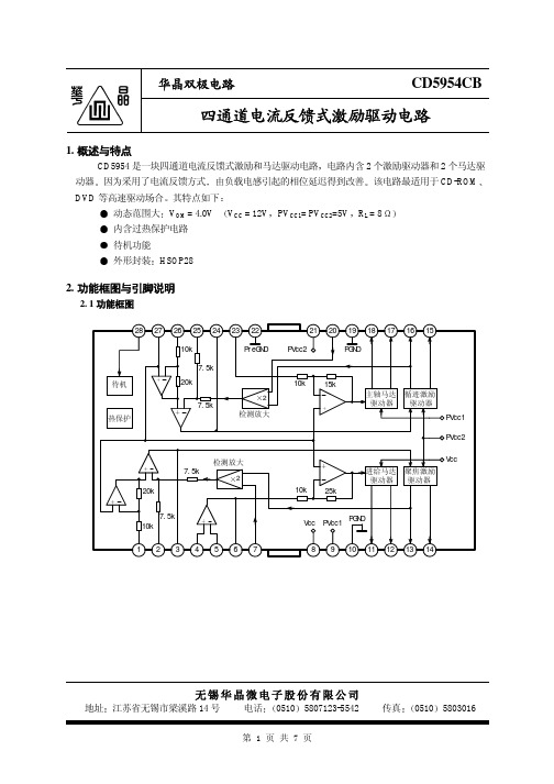
4通道CD/CD-ROM驱动器电路 D5954概述:D5954 是一块用于驱动CD/ CD-ROM、 DVD-ROM、封装外形图DVD-PLAYER的马达和线圈的4通道BTL集成电路。
由于使用了电流反馈,由负载的变化而引起的电流相位变化最小。
电路采用HSOP-28封装形式。
主要特点:内置双通道电流反馈型驱动器和双通道马达驱动器。
动态范围宽(4.0V(典型)(Vcc=12V, PVcc=5V, RL=8Ω))进给电机部分、主轴电机部分、聚焦和循迹部分电源分离,使在低电源电压驱动时有较好功率 内设热保护电路内设待机模式功能框图引出端功能符号引出端序 号 功 能符 号引出端序 号功 能符 号 1聚焦输入VINFC 15 循迹线圈正输出端VOTK+2 CECerr1 16 循迹线圈负输出端VOTK- 3 误差放大器连接电容 CECerr2 17 主轴驱动正输出端 OLD+ 4 进给放大器正输入端 VINSL+ 18 主轴驱动负输出端 VOLD- 5 进给放大器负输入端 VINSL- 19 功率地 PGND 6 进给放大器输出端 VOSL 20 循迹反馈VNFTK 7 聚焦线圈驱动反馈 VNFFC 21 聚焦、循迹部分电源 PVcc2 8 预驱动及进给驱动电源 Vcc 22 预驱动部分地 PreGND 9 主轴驱动电源 PVcc1 23 主轴驱动输入 VINLD 10 功率地PGND 24CTKerr2 11 进给驱动负输出端 VOSL- 25 误差放大器连接电容CTKerr1 12 进给驱动正输出端 VOSL+ 26 循迹输入 VINTK 13 聚焦负输出端 VOFC- 27 偏置电压输入 BIAS 14 聚焦正输出端VOFC+ 28 待机控制输入STBY极限值(若无其它规定,Tamb=25℃)参数符号数值单位电源电压 Vcc ,PVcc1/2 13.5 V功耗 PD 1.7* W 工作温度 Topr -35~85 °C 贮存温度Tstg -55~150 °C* 安装在70×70×1.6 mm 3的环氧板上,在25°C 以上时,功耗降低13.6mW/°C 。
CD595
-50 0 50
3.6 4.0
13.5 15.5 17.5
0
1
2
待机工作电流 待机工作电压 待机关断电压
IST VSTON VSTOFF
0.5
0
0.5
2.0
单位
mA
mA V A/V
V
mA V mA mA mV V dB
mV V dB dB
mA V V
第3页共7页
华晶双极电路
4. 测试线路
CD5954CB
相位 (deg)
第5页共7页
华晶双极电路
6. 应用线路与应用说明
6. 1 应用线路
DSP
CD5954CB
u- COM
进给 聚焦 循迹 偏压 待机 主轴
100pF
28 27 26 25 24 23 22
10k
待机 热保护
7.5k 20k
7.5k
2 检测放大
7.5k
检测放大 2
20k
7.5k 10k
1234567
8 4
2
1
0
-1
-2
-3
-4
-5
-2 -1 0
1
2
输入电压 V IN (V)
进给驱动器前级运放频率特性
10k
60
+
180
-
20k
40
90
g
100
Vin
20
0
0
Vcc=12V, -20 PVcc1=
PVcc2=5V
10k
ห้องสมุดไป่ตู้
100k
1M
频率 f (Hz)
-90 -180 10M
电信保护产品目录说明书

Contents70 Type indicating fuses —125 AC300 DC 1/10-101015087 holders for 70 Type fuses 130012Circuit protection for telecom applicationsTPC fuses and TPCDS pullout disconnects Telpower TPC compact current-limiting fuses mount in theTPCDS compact fused pulloutdisconnect that’s available intwo disconnect profiles anda variety of terminal styles.Recommended 0.75" center-to-center product spacing.Ratings•Volts 80 Vdc•Amps 3-125 A•IR 100 kAAgency information•UL Recognized (investigated to UL 1801) as a disconnect switch for the interruption of load current by means of withdrawing the fuse pullout•Recognized to US and Canadian requirements under the component recognition program of Underwriters Laboratories Inc. Files E219046 and E56412•CETypical applications•Telecommunications DC power circuit protection •Replacement of DC telecom circuit breakers•Applications where venting of arc or molten metals and gases during opening would pose a problem to surrounding devicesFeatures•Highest interrupting rating (100 kA) available and complete system coordination for DC circuit protection for compact footprint providing a superior protection solution for replacement of existing DC telecom circuit breakers•AmpColor ID™ system makes fuse replacement easy•Local and remote open fuse indication. Local alarm indication provided by LED on TPC fuse•Remote alarm terminal available in three positions common to DC circuit protection devicesTPC fusesTPC-4TPC-10TPC-30TPC-90TPC-5TPC-12TPC-40TPC-100TPC-6TPC-15TPC-50TPC-125TPC-7TPC-20TPC-60Data sheet no. 5023TPCDS catalog number systemTPCDS-BBE-2TPCDS-BSE-3TPCDS-SSM-1TPCDS-D-SEC2* TPCDS-BBE-3TPCDS-BSM-1TPCDS-SSM-2TPCDS-D-SMC1* TPCDS-BBM-1TPCDS-BSM-2TPCDS-SSM-3TPCDS-D-SMC2* TPCDS-BBM-2TPCDS-BSM-3TPCDS-D-BC1*TPCDS-BBM-3TPCDS-SSE-1TPCDS-D-BC2*TPCDS-BSE-1TPCDS-SSE-2TPCDS-D-CC1** Not investigated to Canadian requirements.Dimensions•See data sheet no. 5023T e l e c o m p r o t e c t i o n p r o d u c t sTPM fuse and TPMDS pullout disconnectTelpower TPM miniaturecurrent-limiting fusses mount in the miniature TPMDS pullout disconnect. The TPM fusesfeature local open fuse indication and TPMDS is easily integrated into remote indication systems.Ratings•Volts 80 Vdc •Amps 3-30 A•IR 20 kAAgency information•UL Recognized (investigated to UL 1801) as a disconnect switch for the interruption of load current by means of withdrawing the fuse pullout•Recognized to US and Canadian requirements under thecomponent recognition program of Underwriters Laboratories Inc. Files E219046 and E56412•CETypical applications•Telecommunications DC power circuit protection•Applications with restricted space, or mounting in 1 U (1.75"/44.5mm) panelsFeatures•Smallest and most versatile fused disconnect switch available allowing for assembly into 1 U (1.75"/44.5mm) panel. Easy to connect:•Load: 1/4" quick-connect or bolted connection with 10-32 (M5) captive nut•Line: 1/4" quick-connect or screw connection with clearance hole for #10 (M5) bolt•AmpColor ID™ System makes fuse replacement easy•Switch design provides for easy panel mounting by single captive 4-40 (M3) nut and panel notch integral to switch footprint•Complete system coordination capability with local and remote open fuse indication. Local alarm indication provided by LED on TPM fuse (maximum alarm circuit current: 20 mA)TPM fusesTPM-4TPM-7TPM-12TPM-25TPM-5TPM-8TPM-15TPM-30TPMDS pullout disconnects (accept all TPM fuse ampratings)TPMDS-MPullout fused disconnect, metric hardwareDimensions — see data sheet no. 5022Data sheet no. 5022TPMDS alarm schematicNotes:1. The resistance (R) must be provided by the end-user to limit the open fuse indication output current to a maximum of 20mA. The “R” value should be calculated using the system voltage value. If remote indication functionality is not required, the END-USER CIRCUITRY must still be supplied to provide aresistance path to the return for the local indication to properly function.2 The fuse is polarized to maintain proper orientation with the switch housing. The line and load terminals are identified on the switch housing.TP15900-4 fused pullout disconnect for TPA fuses 4-pole fused pullout disconnectfor use with Telpower TPA andTPA-B fuses. Pullout disconnectsfeature remote open fuseindication capability.Ratings•Volts•145 Vdc@40 A per pole•80 Vdc@50 A per poleAgency information•UL Recognized File E97649 as a disconnect switch for interruption of load current by means of withdrawing the fuse carrier•UL Recognized as a component for telecommunication power distribution equipment (UL category QPQY2)•UL Recognized fuses for branch circuit protection•CSA Component Acceptance for the system•CETypical applications•Telecommunications DC power circuit protectionFeatures•Easy installation, connects directly to busbar, reduces external wiring per pole. Rear accessibility for line and load terminations•LED alarm signaling (LED current 30 mA max)•Local and remote open-fuse indication along with fuse orientation rejection feature and fuse presence indication•Alarm test probe point allows on-site alarm circuit checkingTP15900-414-pole common disconnect w/ split alarm, split lineAvailable fusesTPA-B20, 25, 306520 kA Accessories•Spare fuse holders: catalog numbers 5TPH and TPSFH-ASDimensions — mm (in)TP15914 fused pullout disconnectModular 4-pole fused pulloutdisconnect for us with TPA fuses.4-poles per module can be gangedup to four modules for a total of16 poles. The TP15914 featuresopen fuse indication and fusepresence indication along with fuseorientation rejection.Ratings•Volts 145 Vdc•Amps 50 A max per poleAgency information•UL Recognized, Guide JFHR2, File E56412•UL Recognized as a disconnect switch for interruption of load current by means of withdrawing the fuse carrier•UL Recognized as a component for telecommunication power distribution equipment (UL category QPQYZ)•UL Recognized fuses for branch circuit protection•CSA Certified, Class 1422-30, File 53787•CSA Component Acceptance for the systemTypical applications•Telecommunications DC power circuit protectionFeatures•Easy installation with totally enclosed module that connects directly to busbar to reduce external per-pole wiring.•Standard front access load and line double lug connection for 8 AWG wire•LED alarm signaling (LED current 30 mA max)•Remote alarm with alarm test probe point to allow on-site alarmcircuit checkingTP15914-1Metric hardware Accessories•Spare fuse holders: catalog numbers 5TPH and TPSFH-ASDimensions — mm (in)Data sheet no. 5001Data sheet no. 5011TPA and TPA-B indicating fusesIndicating DC power distribution fuse for use inTP15900-4 and TP15914 fused pullout disconnects.Ratings•Volts•170 Vdc (TPA)•65 Vdc (TPA-B)•Amps•3-50 A (TPA)•20-30 A (TPA-B)•IR•100 kA (TPA)•20 kA (TPA-B)Agency information•UL Recognized, Guide JFHR2, File E56412•CSA Certified, Class 1422-30, File 53787•CE, RoHS compliantTypical applications•Telecommunications DC power circuit protectionFeatures•Indication pin provides for local and remote indication whenused with Bussmann series TP15900-4 and TP15914 disconnectswitches•Patented “orange ring” fuse orientation features assures correctfuse position•The UL Recognized ratings and current-limiting capabilitymake this fuse ideal for cable protection on existing DC powerdistribution systems•A unique blue label is used on all Telpower fuses to designate theirDC capabilityAccessories•Spare fuse holders: 5 position holder; 5TPH; 6 position holder;TPSFH-ASDimensions — in (mm)Data sheet no. 50122011/65/EU15800 fused pullout disconnect for the TPS fuseFused pullout disconnect switchfor use only with the TPS mainfuses (1 to 70 amp) and GMT-Aindicating fuse (see page 14-11).It is recommend to also use theGMT-X cover for the GMT-Afuse.Ratings•Volts 60 Vdc•Amps 3-70 A•SCCR 100 kAAgency information•UL Recognized, Guide QPQY2, File E97649•CETypical applications•Telecommunications DC power circuit protectionFeatures•Alarm output with wire wrap terminal or connection to 0.063”thick common alarm busAccessories•Spare fuse holders: catalog numbers TPSFH-AS (TPS fuses) andTPSFH-T (GMT fuses)Dimensions — in (mm)Data sheet no. 5002TP158HC fused pullout disconnectHigh amp panel mount, rear access fused pullout disconnect for use only with TelpowerTPL-B main fuses (70-250 A) and GMT-A indicating fuse (see page 14-11). It is recommend to also use the GMT-X cover for the GMT-A fuse.Ratings•Volts 80 Vdc •Amps 70-250 A•SCCR 100 kAAgency information•UL Recognized (investigated to UL 1801) as a disconnect switch for the interruption of load current by means of withdrawing the fuse pullout, Guide QPQY2, File E97649Typical applications•Telecommunications DC power circuit protectionFeatures•Similar profile, mounting method, and backplane configuration as 15800. The TP158HC can be installed into existing 15800 panels using the space of two 15800 pullout disconnects•Innovative new fuse pullout design eliminates need for tools to replace the Telpower type TPL-B fuse•Alarm output with wire wrap terminal or connection to 0.063 inch (1.6mm) thick common alarm bus•Hardware included: Load: washer, split lockwasher, and 5/16 - 18 nut (metric M8 x 1.25)TP158HC-MMetricAccessories•Spare fuse holders: TPSFH-LB (TPL-B fuses) and TPSFH-T (GMT fuses)Dimensions•See data sheet no. 5021Application notesThe line connection uses a 1/4-20 bolt (metric M6 x 1) that threads into the line terminal. The line terminal is designed with a float of ±0.02" (±0.50mm) to allow for variation in the distance between the TP158HC mounting flange and the line busbar (see dimensions). Equipment should be designed to eliminate any relative movement between the TP158HC mounting flange and the line busbar.The alarm circuit is not intended for pre-charging capacitive circuits. Maximum alarm circuit current 1 A.TPS main power fuseNon-indicating DC power distribution ferrule fuses specifically designed to meet the unique needs of DC power distribution systems. For use with Bussmann series 15800 fused pullout disconnect. Vertical and horizontal PCB tab versions available for circuit board applications.Ratings•Volts 170 Vdc •Amps 1-80 A•IR 100 kAAgency information•UL Recognized, Guide JFHR2, File E56412, RoHS compliant, CETypical applications•Telecommunications DC power circuit protection•Applications requiring printed circuit board mountingFeatures•The UL Recognized ratings and current-limiting capabilitymake this fuse ideal for cable protection on existing DC power distribution systems•A unique blue label is used on all Telpower fuses to designate their DC capability•PCB tab versions eliminate the need for fuseclips when mountingthe fuse on a circuit board* LB = Bolt tagAccessories•Spare fuse holder TPSFH-AS, see page 15-4Dimensions — in (mm)Data sheet no. 5009Data sheet no. 50212011/65/EUT e l e c o m p r o t e c t i o n p r o d u c t s15100 fused pullout disconnectFused pullout disconnect system for use with TPL Telpower fuses.Ratings•Volts 60 Vdc •Amps 70-800 A•SCCR 100 kAAgency information•UL Recognized, Guide QPQY2, File E97649•CETypical applications•Telecommunications DC power circuit protectionFeatures•Single-pole fusible disconnect switch for primary DC power distribution•Robust housing and terminal construction for demanding applications •Panel mounting•Easily connected to line or load bus15100-601300-800Dimensions — in (mm)Data sheet no. 5003TPHCS high current fused pullout disconnectHigh current fused pullout disconnect for use with TPL-B, TPL-C and TPH Telpower fuses. Available as acomplete pullout disconnect or just the pullout. Base may be purchased separately.Ratings•Volts 80 Vdc •Amps 70-800 A•SCCR 100 kAAgency information•UL Recognized (investigated to UL 1801) as a disconnect switch for the interruption of load current by means of withdrawing the fuse carrier•UL Recognized to meet the requirements for Canadian StandardsTypical applications•Telecommunications DC power circuit protectionFeatures•Innovative design eliminates needing tools to replace the TPL-B, TPL-C or TPH fuses•Easy to install with captive fasteners for direct busbar mounting (bolts not included). Standard 1/4” quick-connect for easy remote alarm connection•Optional electronic alarm eliminates needing parallel indicating fuses while providing local and remote open-fuse indication(maximum remote alarm current: 20 mA); Bipolar alarm: designed for both central office and Radio applications, Local LED open fuse indication for easy viewing.•Carrier window allows easy viewing of installed fuse amp rating•Compact design is ideal for today’s high power, high-densitycabinetsTPHCS250-E English TPL-B 70-250TPHCS250-MLMetric, LED TPL-B 70-250TPHCS250-EL English, LED TPL-B 70-250TPHCS250-MAV Metric, alarm TPL-B 70-250TPHCS250-EAVEnglish, alarm TPL-B 70-250TPHCS800-M Metric TPL-C or TPH 300-800TPHCS800-E English TPL-C or TPH 300-800TPHCS800-ML Metric, LED TPL-C or TPH 300-800TPHCS800-EL English, LED TPL-C or TPH 300-800TPHCS800-MAVMetric, alarm TPL-C or TPH 300-800TPHCS800-EAVEnglish, alarmTPL-C or TPH300-800TPHCS800-MAV shownData sheet no. 5020TPL high amp DC fusesHigh amp DC power distribution fuses for use with Telpower 15100, 15200, TP158HC and TPHCS fused pullout disconnects. TPL-TA adapter kit isnecessary when replacing a UBO fuse.Ratings•Volts 170 Vdc •Amps 70-800 A•IR 100 kAAgency information•UL Recognized Guide JFHR2, File E56412 Bellcore•CETypical applications•Telecommunications power circuit protectionFeatures•Current-limiting design for DC power distribution systems •UL Recognized branch circuit protection •Complete system coordination capability•Energy savings with low watts loss, low operating temperatures, and minimum I 2t levelsAccessories•Spare fuse holders: TPSFH-LB (for TPL-B fuses) TPSFH-LC (for TPL-C fuses)Dimensions — in (mm)Data sheet no. 5005TPL-CN, TPL-CR, TPL-CV and TPL-CZTPHCS800-P Pullout only (800 A)TPL-C or TPH300-800TPHCS-B-M Base only, metric —800 max TPHCS-B-E Base only, English —800 max TPHCS-B-ML Base only, metric, LED —800 max TPHCS-B-EL Base only, English, LED —800 max TPHCS-B-MAV Base only, metric, alarm —800 max TPHCS-B-EAVBase only, English, alarm—800 maxNotes1. TPHCS250 and TPHCS800 pullouts and bases are the same with exception to the fuse type the pullout will hold (TPL-B, TPL-C or TPH).2. Plastic rated UL 94V0, 140ºC RTI.Dimensions — mm (in)Data sheet no. 5020T e l e c o m p r o t e c t i o n p r o d u c t sTPN high amp current limiting DC fusesThe TPN fuse is a current-limiting DC power distribution fuse that’s dimensionally similar to UL Class R branch circuit fuses making them easy to install using standard RM60_ modular Class R fuse blocks.Ratings•Volts 170 Vdc •Amps 1-600 A•IR 100 kAAgency information•UL Recognized, Guide JFHR2, File E56412Typical applications•Telecommunications power circuit protectionFeatures•Current-limiting design for DC power distribution systems •Recognized branch circuit protection •Complete system coordination capability•Energy savings with low watts loss, low operating temperatures, and minimum I 2t levelsTPN-3TPN-35TPN-100TPN-300TPN-5TPN-40TPN-110TPN-350TPN-6TPN-45TPN-125TPN-400TPN-10TPN-50TPN-150TPN-450TPN-15TPN-60TPN-175TPN-500TPN-20TPN-70TPN-200TPN-600TPN-25TPN-80TPN-225Accessories•Spare fuse holders:TPSFH-N30 (for TPN 1-30) TPSFH-N60 (for TPN 35-60)Recommended modular* Class R fuse blocksRM25060-1CR 60RM25100-1CR 100RM25200-1CR 200RM25400-1CR 400RM25600-1CR600* Blocks can be snapped together to create the number of required poles. Optional indicating and non-indicating finger-safe covers available for all blocks.Data sheet no. 50060.81(21)35 A to 60 A0.5670A to 100A110A to 200A225A to 400A1.56(38)1.06(27)Dimensions — in (mm)70 Type pin indicating fusesPin indicating fuse for use in the 15087 panel-mount fuse holder. Ratings•Volts•125 Vac•300 Vdc•Amps 1/10-10 A•IR 1 kA @ 300 VdcAgency information•UL Recognized, Guide JDYX2, File E19180 Bellcore•CE70R-15/100A*Red/White101384550KS23751-L11 70E-18/100A*Y ellow100203363KS23751-L5 70X-2/10A Black——70F-1/4A*Violet100203371KS23751-L6 70K-1/4A*Violet/White100203405KS23751-L9 70G-1/2A*Red100203389KS23751-L7 70H-3/4A*Brown100203397KS23751-L8 70I-1A Pink——70A-1-1/3A*†White100203322KS23751-L1 70B-2A*Orange100203330KS23751-L2 70C-3A*Blue100203348KS23751-L3 70J-3-1/2A Black/White——70D-5A*Grn/Black100203355KS23751-L4 70L-6A Grn/White——70M-8A Brown/White——70N-10A Violet/Y ellow——72A Plastic Case (dummy)100203421—72B Blister Pack (dummy)103757977—* Product designed to comply with Bellcore Technical Reference TR-TSY-000799 Issue 1, December 1988.† Not UL Recognized.Data sheet no. 500715087 fuse holderPanel mount fuse holder for use with 70 Type fuses.Ratings•Volts 300 Vdc•Amps 12 AAgency information•UL Recognized, Guide IZLT2, File E14853•CEFlammability rating•UL 94V0Catalog number 15087Typical applications•Telecommunications DC power circuit protectionFeatures•Panel mount fuse holder for 70 type fuses supplied with two screws•Remote alarm capabilityOptional color-code eyeletsColor-coded eyelets are used with the fuse holder to indicate itsfuse amp rating.1A1706-0118/100Y ellow1A1706-151/10Gray/White 1A1706-022/10Black1A1706-031/4Violet1A1706-041/4Violet/White 1A1706-051/2Red1A1706-063/4Brown1A1706-071Pink1A1706-081-1/3White1A1706-092Orange1A1706-103Blue1A1706-163-1/2Black/White 1A1706-115Green/Black 1A1706-126Green/White 1A1706-138Brown/White 1A1706-1410Violet/YellowData sheet no. 5007Telecom protection products — 14HLS, HLT, PCT holders for GMT indicating fusesConfigurable fuse holders for use with GMT indicating fuses:•PCT single-pole•HLS 1-25 pole without flanges•HLT 1-25 pole with flangesRatings•Volts 60 Vdc/125 Vac •Amps 15 A per pole•Poles Up to 25 (HLT , HLS)Agency information•UL Recognized, Guide IZLT2, File E14853, 15 A (60 Vdc)•CEFlammability rating•UL 94V0Typical applications•Telecommunications DC power circuit protectionFeatures•Multiple configurations provide application flexibility•Compact size saves spaceHLS 1-25HLT1-25To order, see data sheet no. 5010 for build-a-code to determine:•Body style (HLT or HLS) •Number of poles •Busbar type •Busbar position•Termination locationData sheet no. 5010GMT indicating fuses for HLS, HLT, PCT holdersFast-acting indicating fuses for HLT , HLS and PCT fuse holders.Ratings•Volts•60 Vdc•125 Vac•Amps 18/100 to 15 A•IR•450 A@60 Vdc•300 A@125 VacAgency information•UL Recognized, Guide JFHR2, File E56412•RoHS compliant, CETypical applications•Telecommunications DC power circuit protectionFeatures•Local and remote indication capability•Color coded for easy amp rating identificationGMT-65/100A Black GMT-10A Red/White GMT-3/4A Brown GMT-12A Y ellow/Green GMT-1A Gray GMT-15A Red/Blue GMT-1-1/3A White GMT-Dummy Gray body GMT-1-1/2A White/Y ellow GMT-X Clear cover GMT-2A Orange GMT-YClear cover w/tabGMT-3ABlue* Some GMT ratings may be sold only in bulk pack.Accessories•Spare fuse holder, catalog number TPSFH-TGMT-A fast-acting, open fuse indicatorFast-acting GMT-A open fuse indicator is designed specifically for use in the Telpower 15800 and TP158HC fused pullout disconnects as a means of providing main fuse open indication.Agency information•UL Recognized, Guide JFHR2, File E56412 •RoHS compliant•CECatalog no./color code: GMT-A/YellowGMT - Dummy2011/65/EU2011/65/EUData sheet no. 500814-11BUSSMANN SERIES FULL LINE CATALOG 1007 — OCTOBER 2018/bussmannseriesWith the Bussmann TM series Quik-Spec™ Coordination Panelboard (QSCP), it’s simple and cost-effective to selectively coordinate using published circuit breaker/fuse and fuse/fuse ratio tables.What’s more, the compact panelboard features a footprint equal to circuit breaker panels but 40% smaller than traditional fusible panels. Its safety-focused design includes finger-safe branches, branch fuse interlock and fuse ampacity rejection.And with up to 200 kA short-circuit current rating (SCCR), the QSCP easily withstands high fault currents.Learn more at /bussmannseries .SERIESFollow us on social media to get the latest product and support information.Selective coordination has never been easier.。
商品说明书:美国品牌电子产品-冷柜型号

CATÁLOGOINSTALACIÓN (4)LISTA DE CARACTERÍSTIOAS (3)MEDIDAS DE SEGURIDAD IMPORTANTES (2).OPERACIÓN (5)SUGERENCIAS EN EL ALMACENAMIENTO DE ALIMENTOS (6).CUIDADO Y LIMPIEZA (7)INFORMACIÓN GENERAL (7)REINSTALACION DE LA CHARNELA DE LA PUERTA(Opcional) (8)ANTES DE LLAMAR AL SERVICIO TÉCNICO (9)Para comenzarControl de temperatura Para hacer hieloDescongelaciónNo utiliceprolongadores Si es posible, conecte el frigorífico-congelador a unatoma de corriente individual para impedir que éste yotros aparatos o las luces domésticas provoquen unasobrecarga.Substitución de Sustitución del cable de alimentaciónSi el cable hizo daño, debe consultar a la agencia deservicios o a la productora para evitar el peligro.Conexión a tierraEn caso de un corto-circuito, la conexión a tierra reduce elriesgo de un electrochoque ya que proporciona a lacorriente eléctrica un cable de descarga. Para evitar unposible electrochoque, este aparato debe estar conectadoa tierra. Un uso inadecuado del enchufe de conexiónpuede dar lugar a un electrochoque. Acuda a unelectricista cualificado o a personal de mantenimiento sino entiende totalmente las instrucciones relativas a laconexión a tierra o si no está seguro de que el aparatoestá debidamente conectado a tierra. Esta aparato deberá conectarse a tierra(masa)NO ESPERE, HÁGALO AHO ATRACCIÓN MUY PELIGROSAUn refrigerador vacío puede constituir una atracción peligrosa para los niños. Quite las juntas,enganches, tapas o la puerta completa de laaplicación no utilizada o adopte las medidasnecesarias para que no constituya peligro alguno.No grarde materiales inflamables, explosivos oproductos químicos dentro del refrigerador.Esta guía contiene muchos mensajes de seguridadimportantes. Lea y cumpla siempre estos mensajes deseguridad.Éste es el símbolo de alerta de seguridad. Este símbolole avisa de mensajes de seguridad que le informan depeligros que pueden causar la muerte o daños a usted, aotras personas o al producto. Todos los mensajes deseguridad vendrán precedidos por el símbolo de alerta deseguridad y la palabra señalizadora de peligro PELIGRO,ADVERTENCIA o PRECAUCIÓN. Estas palabras significan:Si no cumple con las instruccionescorrerá peligro de muerte o de lesionesgraves.Si no sigue las instruccionespuede correr peligro de muerte ode lesiones graves.Indica una situación peligrosainminente que, si no se evita,podría causar lesiones menores omoderadas, o sólo daños alproducto.Todos los mensajes de seguridad identificarán el peligro,le informarán de cómo reducir la posibilidad de lesiones yde qué puede pasar si no se cumplen las instrucciones.PRECAUCIÓNEste dispositivo no está destinado para ser utilizado por personas (incluyendo a niños)disminuidas físicas, mentales o sensoriales, o sin experiencia o conocimiento, a menos que lo hagan bajo supervisión o hayan recibido instrucciones sobre el uso del dispositivo por parte de una persona responsable de su seguridad. Los niños deben estar siempre supervisados para garantizar que no jueguen con el electrodoméstico. PRECAUCIONES BÁSICAS DE SEGURIDADPELIGROADVERTENCIAPRECAUCIÓN5 12 346 7 891. Evaporador: No use ningún objeto agudo para quitar el hielo o lo congelado. Esto podria danar el evaporador.2. Bandeja de Hielo3. Estantes del Refrigerador4. Barra P.V.C : Para ensaladas, frutas y vegetales.5. Elagir los articulos del Drip Tray y Chiller Tray (Parte Opcional):Drip Tray ; Usa como el sostér del aguaque cal cuando se liquida por evaporacién. : Chiller Tray ; Para liquidarse.Puede usar como Drip Tray.6. Disco del Control de la Temperatura7. Redecilla de la Puerta del Refrigerador8. Sello de la Puerta Magnética9. Tornillo Nivelador1. Seleccione una ubicación adecuada coloque elfrigorífico en un lugar de fácil acceso.2. No sitúe el frigorífico cerca de fuentes de calorni lo exponga a la luz solar directa o a lahumedad.3. Para un funcionamiento correcto del frigorífico,permita que el aire circule libremente en tornoal mismo.Si coloca el frigorífico empotrado en la pared,deje al menos una separación de 30cm o másrespecto de la parte superior y 5cm o más conrelación a la pared.El frigorífico deberá elevarse 2,5cm o más conrespecto al suelo, especialmente si éste éstaenmoquetado.4. El frigorífico deberá estar totalmente niveladopara evitar vibraciones.Si fuera necesario, ajuste el(los) tornillo(s) denivelación para compensar las posiblesirregularidades del suelo.Para que las puertas cierren correctamente, laparte frontal deberá estar ligeramente más altaque la parte posterior.El(los) tornillo(s) puede(n) girarse fácilmenteinclinando ligeramente el frigorífico.Gire el(los) tornillo(s) de nivelación en elsentido de las agujas del reloj para elevar elfrigorífico y en sentido contrario para bajarlo. 5. Instale este equipo electrodoméstico a una temperatura comprendida entre 10°y 43°C. Si la temperatura alrededor del equipo es demasiado alta o demasiado baja esta, esto podría disminuir su capacidad de enfriamiento.6. Limpie el polvo acumulado durante el transporte y la totalidad del frigorífico.7. Instalar los accesorios como la cubitera, etc, en el lugar adecuado. Están embalados conjuntamente para evitar posibles daños durante su transporte.8. Conectar el cable de alimentación eléctrica (o enchufe) a la salida. No conectar otros electrodomésticos en esta misma salida.9 . Antes de almacenar los productos alimenticios,encender el refrigerador durante 2 ó 3 horas. Comprobar el flujo de aire frío en el compartimento del congelador para garantizar un enfriamiento adecuado. Su refrigerador yaestá listo para su uso.ESTE FRIGORÍFICO HA SIDO FABRICADO CON EXTREMO CUIDADO Y EMPLEANDO LAS ÚLTIMAS INNOVACIONES TECNOLÓGICAS.ESPERAMOS QUE SE SIENTA COMPLETAMENTE SATISFECHO CON SUS PRESTACIONES Y RENDIMIENTO.ANTES DE UTILIZAR EL FRIGORÍFICO, LEA ESTE MANUAL EN SU TOTALIDAD. EN ÉL SE PROPORCIONAN LAS INSTRUCCIONES EXACTAS PARA SU INSTALACIÓN, EMPLEO Y MANTENIMIENTO, ASÍ COMO ALGUNOS CONSEJOS ÚTILES.CONTROL DE TEMPERATURAPARA COMENZARCuando haya instalado su refrigerador, deje pasar 2 o 3 horas para que se estabilice la operación a temperatura normal antes de llenarlo con alimentos.Cuando haya sido interrumpido deje pasar 5 minutos antes de encender de nuevo.Para empezar ajuste el control del refrigerador en posición media.Para temperaturas más frías, ajuste el control de temperatura deseada a un número mayor.PARA HACER HIELOPara hacer cubos de hielo, llene la charola conagua y colóquelo dentro del evaporador.Para sacar los cubos de hielo, tuersasuavemente sujetando la charola de susextremos.ADVERTENCIA: Llenar con agua potable solamenteDESCONGELACIÓNNo use ningún instrumento agudo o metálico para quitar el hielo, locongelado o capas de hielo del evaporador.PRECAUCIONEs necesario descongelar regularmente para asegurar una operación eficas del refrigerador. Cuando el espesor del hielo/congelado en la superficie del evaporador alcanza un cuarto de una pulgada(6 mm), empiece la operación de descogelación.Para descongelar, gire el control a "0".Durante la descongelación, quite los alimentos del evaporador y coloque la bandeja de gotera en una posición apropiada.Después de descongelar, quite la bandeja de gotera, vacie el agua de la bandeja, sequela y colóquela de nuevo en su posición normal. Coloque el control en la posicion deseada.●Al almacenar alimentos calientes asegúrece de enfriarlo antes.●Cuando esté almacenando, cubra el alimento con una convertura de vinilo o almacene en un contenedor con tapa.Cuando se evapora la humedad del alimento, se pierde el sabor y la nutrición del alimento.●No almacene botellas en el evaporador, ya que puede romperce al ser congelado.●No congele de nuevo un alimento que una vez haya sido derretido y congelado, ya que causará la pérdida del sabor y nutrición.●Almacene los alimentos después de haberlos lavado, para no contaminar los alimentos adyacentes.Limpieza - InteriorPara limpiar el interior, use una tela suave con una solución de un cuarto de litro de agua con una cuchara grande de soda para hornear, o con algo de detergente suave. Esto límpia y neutraliza los olores. Enjuague con agua y séquelo. Limpie la parte interna de la misma manera.Limpieza - ExteriorUse una solución tibia de jabón suave o detergente para limpiar el exterior de su refrigerador. Enjuague con una tela limpia y humeda, después séquelo. Limpieza - Precausiones●Desconecte siempre el cordón de potencia del enchufe eléctrico cuando este limpiando alrededor de las partes eléctricas.●No use liquidos inflamables o tóxicos para limpiar.●No use trapos metálicos, cepillos, limpiadores tosco abrasivos o soluciones de fuerte alcalino en ninguna supericie.●Cuidado durante las Vacaciones: Para unas vacaciones largas, desconecte el cordón de potencia y deje la puerta abierta para prevenir olores. Para unas vacaciones cortas, retire los alimentos frescos deje el control en operación normal.●Cuidados al Trasladar: Asegure todos losartículos sueltos en sus lugares con seguridad, usando una cinta adhesiva para prevenircualquier daño, y levante el tornillo nivelador.VACACIONESEn unas vacaciones de corta duración, probablemente lo mejor será dejar el frigorífico funcionando. Introduzca en el congelador los alimentos que puedan congelarse para una mayor conservación. Cuando piense estar fuera durante un período prolongado de tiempo, saque todos los alimentos, desconecte el cable de alimentación, limpie completamente el interior y deje ABIERTAS las puertas para impedir la formación de olores.CORTES ELECTRICOSLa mayoría de los cortes de la alimentación se solucionan en una o dos horas y no afectan a las temperaturas del frigorífico. Sin embargo, deberáevitarse abrir las puertas durante los corteseléctricos. Cuando se produzcan cortes prolongados, coloque un bloque de hielo seco sobre los paquetes congelados. MUDANZASQuite o fije de un mode seguro todos los componentes extraíbles del interior del refrigerador. Para evitar daños en el(los) tornillo(s) de nivelación, introdúzcalos completamente en la base.El refrigerador ha sido diseñado con puerta reversible en tal modo que se pueda abrir ya sea por la derecha que por la izquierda. Es mejor reinstalar la charnela de la puerta al principio porque es incómodo efectuarlo después.Para cambiar la charnela de la puerta le rogamos que consulte el diagrama que damos a1. Quite todos los accesorios de ajuste flojos del interior del dispositivo.2. Con cuidado, apoye el dispositivo sobre la parte posterior en el empaque original (Va a necesitar ayuda para realizarlo). Tenga cuidado de no arruinar las tuberías manteniéndolas alejadas del piso.3. Destornille y quite el pié ajustable (A).4. Quite la charnela inferior (D) destornillando los dos pernos (B).5. Quite la pata (H) destornillando el perno que la sujeta (C).6. Suavemente tire la puerta hacia abajo para quitarla.7. Antes de volver a encajar la puerta, cambie la Cápsula de la charnela (F) haciendo palanca sobre la misma desde su posición usual y reinstalándola sobre el otro lado de la puerta. Debe ponerse cuidado de no dañar las superficies adyacentes cuando quite la Cápsula de la Charnela.8. Destornille el clavillo de la Charnela Superior (G) y atorníllelo en el agujero del lado opuesto,en el tope del mueble.9. Ahora sujete la Charnela Inferior (D) al mueble utilizando los dos pernos (B).10. Substituya el Pié Ajustable (A), poniéndolo a 20 mm aproximadamente.11. Con cuidado levante el dispositivo (Va a necesitar ayuda para hacerlo) y póngalo en la posición definitiva.12. Controle que la puerta se abre y cierra con facilidad. Asegúrese que el cierre hermético de la puerta no apoye sobre un lado de la charnela creando boquetes que dejen entrar aire en el interior. Ajuste las charnelas si fuera necesario.Este dispositivo debe estar apoyado sobre una superficie firme y pareja con espacio suficiente para que circule aire alrededor del mismo. (Por lo menos 10 mm por todos los lados y según la posición, 20 mm debajo de la tabla de trabajo). Evite las posiciones en proximidad de paredes orincones. Tiene que haber suficiente espacio para la libre circulación de aire especialmente en la parte posterior. Esta unidad debe estar alejada de fuentes directas de calor como cocinas,radiadores y luz directa del sol. Si la unidad está puesta en un lugar en el que la temperatura es demasiado baja, se formará condensación en la parte externa del mueble. Recomendamos la temperatura normal de la habitacón.Evite posiciones en las que puede haber corrientes o humedad porque esto puede afectar la eficacia del producto.EN MUCHAS OCASIONES PUEDEN EVITARSE LAS LLAMADAS AL SERVICIO TÉCNICO!SI CREE QUE EL FRIGORÍFICO NO FUNCIONA DEL MODO ADECUADO, COMPRUEBE EN PRIMER。
LED恒流IC芯片大盘点模板

LED恒流IC芯片大盘点模板在现代电子产品中,LED光源被广泛应用于照明、显示、通信和传感等领域。
为了保证LED光源的稳定工作和延长寿命,需要使用LED恒流IC芯片控制LED电流的大小。
本文将对LED恒流IC芯片进行大盘点,介绍常用的IC芯片以及其特点和应用领域。
一、LM3414是一款高效率、非同步降压转换器,主要用于LED驱动器。
其具有输入电压范围广泛、恒定电流输出、频率可调等特点,适用于照明和背光系统等领域。
二、LT3762是一款高效的双级LED恒流驱动器,适用于大功率LED照明应用。
它具有宽输入电压范围、高电流精度、PWM和直流调光功能等特点,适用于室内和室外照明系统。
五、AL8810是一款高效的LED恒流驱动器,可用于大功率LED照明应用。
它具有高精确度、宽输入电压范围、过热保护和短路保护等特点,适用于室内照明和汽车照明等领域。
六、BD1835是一款高效的恒流LED驱动器,适用于背光和照明系统。
它具有高效率、电流精确度、PWM和直流调光功能等特点,适用于电视、显示屏和照明灯具等应用。
以上仅是LED恒流IC芯片中的一部分,还有许多其他品牌和型号可供选择。
在选择LED恒流IC芯片时,需要根据具体应用需求来确定合适的芯片型号,包括输入电压范围、输出电流范围、调光功能以及保护功能等。
此外,还需要考虑芯片的可靠性、稳定性和供应商的售后服务等因素。
总结起来,LED恒流IC芯片在LED照明应用中起到了至关重要的作用。
选择合适的芯片可以提高LED光源的效率和稳定性,延长LED的使用寿命。
随着LED照明技术的不断发展,LED恒流IC芯片也将变得更加智能化和高效化,为LED照明行业的发展提供更多可能性。
ad595工作原理

ad595工作原理AD595是一种高性能、高精度的模拟前端信号调理芯片,广泛应用于工业控制、仪器仪表和通信设备等领域。
其工作原理基于模数转换技术和电压控制放大器(VCA)的原理。
在工作中,AD595首先接收来自传感器的模拟电压信号,经过模数转换器进行数字化处理。
模数转换器将连续的模拟信号转换为离散的数字信号,以便于后续的数字处理和分析。
AD595的模数转换器通常采用逐次逼近型(Successive Approximation)的转换方法,具有较高的转换精度和速度。
转换后的数字信号进一步经过数字处理单元,进行校准、增益调节等操作。
其中,校准操作旨在消除传感器和芯片本身的误差,提高系统的测量精度。
增益调节则根据实际应用需求,对信号进行放大或压缩,以适应不同测量范围和精度要求。
接下来,经过数字处理的信号被输入到电压控制放大器(VCA)中。
VCA是AD595的核心部件,负责根据输入信号的大小,调节输出信号的幅度。
VCA通过控制电压信号的放大倍数,实现对输入信号的放大或衰减。
这种电压控制放大的方式,使得AD595能够灵活地适应不同的输入信号范围和输出要求。
经过VCA调节后的信号被输出到外部设备或下游电路中,用于实现各种功能,如数据显示、控制信号生成等。
AD595的输出接口通常采用电压输出形式,输出电压与输入信号成正比,可以直接连接到其他电路或设备中,方便信号的传输和处理。
总的来说,AD595的工作原理基于模数转换技术和电压控制放大器的原理,通过将模拟信号转换为数字信号,并经过校准和放大等处理,实现对输入信号的精确测量和调节。
其高性能和高精度的特点,使得AD595在工业控制和仪器仪表等应用中得到广泛的应用。
- 1、下载文档前请自行甄别文档内容的完整性,平台不提供额外的编辑、内容补充、找答案等附加服务。
- 2、"仅部分预览"的文档,不可在线预览部分如存在完整性等问题,可反馈申请退款(可完整预览的文档不适用该条件!)。
- 3、如文档侵犯您的权益,请联系客服反馈,我们会尽快为您处理(人工客服工作时间:9:00-18:30)。
4-CH MOTOR DRIVE IC- 2-CH BTL driver- 2-CH BTL driver with current mode feedback - Built-in TSD (thermal shut down) circuit. - Built-in power save circuit- Built-in input opamp for SLED channel - Operating supply voltage (4.5V~13.2V).IP5954A is a 4-CH motor driver for CDP/VCDP/DVDP systems. It is composed of 2-CH BTL driver with one input opamp and 2-CH BTL driver with current mode feedback.DESCRIPTIONSBLOCK DIAGRAMORDER INFORMATIONFEATURES28SSOPH-375 DeviceOrder Coder PackagePacking IP5954A 28SSOPH-375 Tube IP5954A-TF T&R IP5954AL Tube, Lead Free IP5954AL-TFT&R, Lead FreeIP5954AB 28SSOPH-375BTube IP5954AB-TFT&RIP5954ABL Tube, Lead Free IP5954ABL-TFT&R, Lead FreeIP5954A28SSOPH-375B4-CH MOTOR DRIVE ICPIN DESCRIPTIONSPIN CONNECTIONSNO SYMBOL I/ODESCRIPTION 1VinFCI Focus input2 CFCerr1- Error amp filter connection 1 for focus actuator3 CFCerr2 -Error amp filter connection 2 for focus actuator 4 VinOP+I OPamp IN(+) for sled driver 5 VinOP- IOPamp IN(-) for sled driver6 VOSL O OPamp out for sled driver7 VNFFC ICurrent feedback pin for focus actuator8 SVCC- Signal supply voltage9 PVCC1- Power supply voltage 110 PGND -Power ground11VOSL- OSled driver output(-) 12VOSL+ OSled driver output(+) 13VOFC- OFocus driver output(-) 14VOFC+OFocus driver output(+)NOSYMBOLI/O DESCRIPTION 15VOTK+ O Tracking driver output(+) 16 VOTK- O Tracking driver output(-) 17VOLD+ O Loading driver output(+) 18 VOLD- O Loading driver output(-) 19 PGND - Power Ground20 VNFTK I Current feedback pin for Tracking actuator 21 PVCC2 - Power supply voltage 2 22 SGND - Signal ground 23 VinLD I Loading input24 CTKerr2 - Error amp filter connection 2 for Tracking actuator 25 CTKerr1 - Error amp filter connection 1 for Tracking actuator 26 VinTK I Tracking input 27 BIAS IBias input28P/SO Power save4-CH MOTOR DRIVE ICCHARACTERISTICS SYMBOL VALUE UNIT Maximum supply voltageVCCmax 15 V Power dissipation Pd28SSOPH-3751.7W28SSOPH-375B 2.3 WOperating temperature Topr -35 ~ +85 OC Storage temperature-55 ~ 150OCTstgNote>1. When mounted on 70mm X 70mm X 1.6mm PCB (Phenolic resin material).2. Power dissipation reduces 13.6 mW/O C for using above Ta=25O C 3. Do not exceed Pd and SOA.POWER DISSIPATION CURVERECOMMENDED OPERATING CONDITIONSCHARACTERISTICS SYMBOL VALUE UNIT Signal supply Voltage VCC1 4.5 ~ 13.2 V Power supply Voltage 2PVCC24.5 ~ 13.2VPower supply Voltage 1 PVCC1 4.5 ~ 13.2 V ABSOLUTE MAXIMUM RATINGSP o w e r D i s s i p a t i o n (m W )Ambient Temperature (°C )25 50 75 100 125 150 1750 12 3P o w e r D i s s i p a t i o n (m W )Ambient Temperature (°C )25 50 75 100 125 150 1750 12 3 28SSOPH-37528SSOPH-375B4-CH MOTOR DRIVE ICELECTRICAL CHARACTERISTICS(SVCC=8.0V,PVCC1=PVCC2=5V, f = 1kHz, RL=12ohm, Rs=0.5ohm, Ta = 25O C unless otherwise specified.) CHARACTERISTICS SYMBOL CONDITIONS MIN TYP MAX UNIT Quiescent circuit current Icc No Load-14-mA Power save on current Ips Pin28=GND--1mA Power save on voltage Vmon Pin28=variation--0.5V Power save off voltage Vmoff Pin28=variation 2.0--V Reference mute on voltage Vrmon Pin27=variation--0.7V Reference mute off voltage Vrmoff Pin27=variation 1.3--V [ ACTUATOR DRIVE PART ]Output offset current Iooa Pin1=Pin9=Pin22=Vref -15015mA Maximum output voltage Voma - 3.6 4.0-V Transmission gain 45 Gma Vin=0.1Vrms, f=1kHz- 1.5-A/V [ LOADING DRIVE PART ]Output offset voltage Vool Vin=Vref -80-+80mV Maximum output voltage Voml - 3.6 4.0-V Closed-loop voltage gain Avfl Vin=0.1Vrms, f=1kHz13.515.517.5dB Slew rate SRl Vout = 4.0Vpp, Square- 1.5-V/usec Ripple rejection ratio RRl Vin=0.1Vrms, f=120Hz5060-dB4-CH MOTOR DRIVE ICELECTRICAL CHARACTERISTICS (Continued)CHARACTERISTICS SYMBOL CONDITIONS MIN TYP MAX UNIT [ SLED DRIVE INPUT OPAMP PART ]Common mode input range Vicm Vbias=4.0V -0.3-7.0V Input bias current Ib -30300nA Low level output voltage Vol -0.10.3V Output source current Isrc -0.20.5-mA Output sink current Isnk -1--mA [ SLED DRIVE PART ]Output offset voltage Voos Vin=Vref -100-+100mVMaximum output voltage Voms SVCC=8.0V,PVCC1=PVCC2=5V, RL=12ohm- 6.0-VClosed-loop voltage gain Avfs Vin=0.1Vrms, f=1kHz182022dB Slew rate SRs Vout = 4.0Vpp, Square- 1.5-V/usec Ripple rejection ratio RRs Vin=0.1Vrms, f=120Hz5060-dB (SVCC=8.0V,PVCC1=PVCC2=5V, f = 1kHz, RL=12ohm, Rs=0.5ohm, Ta = 25O C unless otherwise specified.)4-CH MOTOR DRIVE IC TYPICAL APPLICATION CIRCUIT4-CH MOTOR DRIVE ICINTERNAL CIRCUITPin noPin nameInternal circuit1,23, 26,27VinFC, VinLD, VinTK, Bias2, 7, 20, 25CFCerr1, VNFFC, VNFTK, CTKerr13, 24CFCerr2, CTKerr227126234-CH MOTOR DRIVE ICINTERNAL CIRCUIT (Continued)Pin noPin nameInternal circuit4,5VinOP+, VinOP-28PS11, 12, 13, 14, 15, 16, 17, 18VOSL- VOSL+ VOFC- VOFC+ VOTK+ VOTK- VOLD+ VOLD-4-CH MOTOR DRIVE IC PACKAGE DIMENSION28SSOPH-3754-CH MOTOR DRIVE IC28SSOPH-375BPACKAGE DIMENSION (Continued)。