UFlow 2.2 设计说明
陶氏UF设计软件用法-1.1版byAmber

设计数需认值1. 2.仅以宝来计中大部分需根据项值(给出给打开UF 软输入项目来800m 3/分参数可目需求调给参数的软件,创目信息陶氏UF 1.1版/h 回用水可以用系统整。
在大名称),第建新项目创建新的F 设计软By Am 水为例,简统默认参数大部分说明第二组是本的项目项设设软件用法mber简要说明陶数,流量、明中给出两本项目需项目名称 设计时间 设计人默陶氏UF 软通量、水两组图,一要的实际例系统默认软件用法。
水质等关键一组是软件际参数值。
在键参件默3.4. 5.输入项目下一步选择系统目备注信息统单位息(支持中中文)备注信息,选择公制单支持中文下一步系默单位例统认例系统默认6. 7.选择过滤选择化学系默认滤器参数学试剂的浓统认例浓度化学药品过默品在计量槽中过滤器回收滤器截留粒径系统默认点击这里中存储时间收率径里编辑化学试试剂8.选择报告告书语言系统默认例HCl 、NaO 浓度改为OH 等药剂的常用浓度的9. 下一步(p 总有机碳数值,若计参数。
系默prev 为上一碳(TOC )、若无可靠参统默认一步),进总悬浮物参数,均可例简体请输入进进水水质,超物(TSS )可填未知体中文进水数据超滤进水三,根据项(unknow 色总三要素:色项目信息尽wn ),仅靠色度 总有机碳 总悬浮物 最低温度 平均温度色度(NTU 尽量给出可靠通量控制)、可靠制设10.11.12.下一步选择清洗选择膜参系默认洗方式参数例系统默认例统认化学膜型号UF系统UF系统RO系统RO系统学强化反洗号统进水量统出水量统回收率统渗透流UF量设一个数自默认工程师建议2860,200t以系统进水量设定一个值即个值软件根据自动计算;RO认值议200t以下选以上选2880量与出水即可,另据系统参O用系统选13.注:14. 选择通量:每个参数 选择反洗系默系默量数后面均洗压力例范统默认例统默认均有该参数范围数范围及建建议值建议值膜通量反洗流CEB 清气洗正洗值滤液压力反洗频气洗频量,一般40~流量 清洗流量 洗流量 洗流量力,bar频率,分钟 频率,分钟~5515.16.选择详细流速细参数例系统默认例注:流速进水渗反反正正气根气洗时点击这水流速透流速洗液流入的流洗液流出的流洗流速正洗/浓水流出洗流入的流速根据最经济的时间一般跟反这里输入详细流速流速出的流速速的速度反洗时间一致参数17.18.常规反洗C EB清洗系默认系统默认例洗(在线化统认在线化化学清洗)常规反化学清洗反洗反洗重进气排水反洗反洗正洗阀门正CEBCEB化学重复时间持续时间,秒水持续时间洗1持续时间洗2持续时间洗持续时间门打开/关闭的正洗水来源反洗水来源反洗时随实际进水UF出水中碱洗频率中酸洗频率学试剂浸泡时秒间的动作持续时源时间仅作参考际运行情况调水率,小时率,小时时间,分钟时间考,整19.20.C IP清洗定期清洗系默认(离线化学洗用的化学例例离线化统认系统默认学清洗)学药品学清洗定期清洗用的化学药CIP清洗CIP清洗清洗液流清洁液同时清CEB数设随实酸的名称酸加药量絮凝剂的絮凝剂加氧化剂氧化氧化品洗频率洗持续时间流量重复使用次数洗制动器B与CIP的相设置仅作参考实际运行调整称量的名称加药量的名称化剂的加入位化剂加药量数相关参考,需整位置21. C EB化学药品例例系统默认C EB 化学药品品 酸碱氧酸碱氧加药确定酸的名称 碱的名称 氧化剂的名称酸的加药量碱的加药量氧化剂的加药药量均设为0定反洗时间和进水中加称 药量,根据现场情和用药量加药情况22. C EB化学药品例系统默认CIP化学药品品酸的名称碱的名称氧化剂的名酸的加药碱的加药量氧化剂的加名称药量量加药量23. 费用和动动力系统默认费费用和动力电价 进料泵效进料泵电循环泵效循环泵电反洗泵效反洗泵CIP 泵效CIP 泵电氧化剂氧化剂酸计量酸计量碱计量碱计量效率 电机效率 效率 电机效率 效率 泵电机效率 效率 电机效率 剂计量泵效率 剂计量泵电机量泵效率 量泵电机效率量泵效率 量泵电机效率机效24. 下一步例25.26. 选择分组完成并查系默认例组方式查看报告统认选择分组本例中选择完组方式择1组,即成并查看报告1条线,56告支膜27.28.29.30.如需修改在软件使可保存文再次打开改,返回上使用过程中文件,以便开文件时UF控制面板上一步中可随时回便随时调阅板回到上述步阅报告步骤中上一步项目信息项目设置进水数据系统参数系统配置数置打开已有有项目附::本例的报报告书。
超声波液位仪的设计_毕业设计 精品推荐
学士学位毕业设计(论文)超声波液位仪的设计学生姓名:指导教师:所在学院:专业:目录摘要............................................................... 错误!未定义书签。
ABSTRACT ...........................................................错误!未定义书签。
前言............................................................... 错误!未定义书签。
1 绪论 (1)1.1 课题背景 (1)1.1.1 超声波液位仪的研究背景与内容 (1)1.1.2 超声波液位仪的现状 (1)1.2 论文研究内容 (2)1.2.1 研究内容 (2)1.2.2 论文的章节安排 (3)2 超声波的液位测量原理 (5)2.1 超声液位仪理论基础 (5)2.1.1 超声波介绍 (5)2.1.2 超声波探头的结构和原理 (5)2.1.3 T/R40-16 超声波探头 (7)2.1.4 传感器的指向角Θ (8)2.2 超声波液位仪工作原理 (9)2.2.1 超声波液位仪工作原理 (9)2.2.2 测量盲区 (10)2.3 本章小结 (11)3 硬件总体设计 (12)3.1 超声液位仪总体设计 (12)3.2 单片机电路 (14)3.2.1 复位电路设计 (15)3.2.2 电源电路设计 (16)3.2.3 时钟振荡器 (17)3.3 发射电路 (18)3.4 接收电路 (19)3.5 液晶显示电路 (20)3.6蜂鸣报警电路....................... (21)3.7对电路板进行合理设计 (23)3.8 本章小结 (25)4 系统软件设计 (26)4.1 软件总体设计 (26)4.1.1 软件设计流程图 (26)4.1.2 主程序结构流程图 (27)4.1.3 回波接收流程图 (29)4.1.4 中断程序流程图 (29)4.1.5报警系统子程序 (30)4.2本章小结 (39)5 实验结果分析及改进 (40)5.1实验结果分析 (40)5.2误差分析及改进措施 (47)5.3 本章小结 (48)6 结论与展望 (48)总结 (49)参考文献 (49)致谢 (55)附录一:超声波液位计电路原理图 (55)附录二:超声波液位仪PCB板图 (55)附录三:程序清单 (55)第一章绪论1.1 课题背景1.1.1 超声波液位仪的研究背景与内容超声波液位仪作为一种典型的非接触测量仪器,在很多场合有广泛的应用,诸如工业自动控制,建筑工程测量和水面高度测量等方面。
液偶说明书-中文
4 运输和储存 .................................................................................................错误!未定义书签。
杜邦 WAVE 设计软件 超滤、反渗透、离子交换 三种技术 一套工具说明书

离子交换(IX)超滤(UF)反渗透(RO)三项技术一个工具• 三项技术整合到一个通用的用户友好型界面• 经改进且一致的算法• 统一的数据用于所有产品和工艺来自杜邦的新型WAVE(Water Application Value Engine,水应用价值引擎)建模软件将三项领先技术——超滤、反渗透、离子交换——整合到一个综合工具中。
该软件具有多项优越功能和强大的计算引擎,让您能够更高效、更准地建模,从而更快地设计出性能更优的多技术系统。
杜邦水处理解决方案WAVE 设计软件超滤(UF )特征:• 包括最新的陶氏超滤产品:含XP Fiber 的IntegraFlux ™和IntegraPac ™ UF 模块• 应用于饮用水领域和非饮用水领域产品• 最新的设计指南和压力额定值曲线• 滤膜完整性测试能力• 能够确定化学增强反冲洗(CEB )和就地清洗(CIP )的pH 值,将跨膜压力(TMP )斜率引入BW/CEB/CIP ,为恒定流量与恒定产量进行设计,并使用RO 浓缩液进行清洗反渗透(RO )特征:• 提供计算方面得到改进的最新陶氏反渗透产品数据库, 包括 FilmTec ™ Fortilife ™和FilmTec ™ ECO 元件• 增强的ISD 能力——压力容器中的每个元件现在 都可以唯一地界定• 用ISD 分离渗透液• 旁路、通路及阶段水平回收循环• 新系统水平液压流量计算器• 有可能进行同步批量案例创建的批量建模• 按元件位置发出设计警告• 在报告中增加了压降数据离子交换(IX )特征:• 包括陶氏离子交换全系列产品• 对所有工艺和树脂使用统一的数据• 能够对13个工艺进行建模,包括:软化、脱碱、去矿化、 RO / IX 纯化、冷凝液纯化及硝酸盐去除• 七个IX 再生方案,包括:并流、水或空气阻塞填充床、AMBERPACK ™、UPCORE ™IX 系统,以及内部和 外部混合床建模效率的极大改进WAVE 软件将DuPont ROSA 、UFLOW 、IXCALC 及CADIX 程序的最佳特征进行了升级,同时将关键技术整合到一个通用、省时的用户友好型界面中。
HPF法脱硫工艺设计课程设计正文
中国矿业大学课程设计说明书姓名:桂大强学号: 06082908 学院:化工学院专业班级:过程装备与控制工程08-2设计题目:HPF法脱硫工艺设计指导教师:王启立邓建军2011 年12 月目录第一章序言 (1)1 课程设计的重要性 (1)2 课程设计的任务 (1)3 课程设计的内容和概述 (3)第二章自动工程设计的认识 (7)1 自动工程设计的方法与目的 (7)2 自动工程设计的内容与任务 (8)第三章HPF法脱硫工艺设计的介绍 (10)1 HRF法脱硫工艺简介 (10)1.1 脱硫工艺原理和工艺流程 (10)1.2 HPF法脱硫工艺特点和操作条件 (11)1.3主要工艺操作控制指标 (13)2 控制方案 (13)2.1 自控方案确定原则 (14)2.2 几个典型的控制图 (15)2.3 设计中图形符号的统一规定 (18)第四章自动控制设备的选择 (28)1.几种常见控制装置特点及比较 (28)2、PLC的硬件选型 (29)3 检测仪表与控制阀的选型设计 (32)3.1检测仪表与控制阀的选型设计原则 (32)3.2 温度测量仪表的选型 (34)3.3 压力测量仪表的选型 (34)3.4 流量测量仪表的选型 (35)第五章控制室设计 (36)1 控制式设计要求 (36)2 控制室和仪表盘的设计 (39)3 其他补充说明 (39)第六章仪表连接 (39)1 系统的整体连接 (39)1.1 仪表回路接线与接管图 (40)1.2 仪表盘端子图与仪表盘穿板接头图 (40)2 设计仪表端子图 (41)第七章供电系统 (41)1 仪表供电系统设计 (41)1.1 供电系统设计内容 (41)1.2 仪表供电要求 (42)1.3 对供电交变类型和电压等级的要求 (43)1.4 对供电质量的要求 (43)2 仪表供电配电设计 (44)2.1供电回路分组 (44)2.2 配电方式 (44)弟八章信号报警与连锁系统 (45)1 信号报警、联锁系统设计原则 (45)2 信号报警系统设计 (46)2.1 信号报警系统的组成 (46)3 联锁系统的设计 (48)第九章安全防护与信号接地 (49)1 仪表防爆设计 (50)1.1 防爆设计的重要性 (50)1.2 危险环境的分类 (50)2 仪表接地设计 (50)2.1 接地作用和要求 (50)2.2 接地系统的设计原则与方法 (52)第十章施工试验及验收 (53)1 自控工程的施工 (54)1.1 施工工作内容 (54)2 自控工程的试运行和验收 (55)2.1 仪表的调校 (55)2.2 仪表的试运行 (55)2.3 仪表的交工验收 (55)设计总结 (56)参考文献 (57)第一章序言1 课程设计的重要性本课程设计旨在培养学生初步分析和设计过程控制工程的能力,使学生在修完有关过程控制基本理论课程基础上,通过该课程学习进一步了解过程控制工程方面的相关知识,能够初步掌握过程控制工程设计的程序和方法、相关规程与规定,进行工程设计的表达和相关设计文件编制。
Pellicon 超滤(UF) 浓稠化(DF)操作指南说明书

Notice: The information in this document is subject to change without notice and should not be construed as a commitment by Merck Millipore or an affiliate. Neither Merck Millipore nor any of its affiliates assumes responsibility for any errors that may appear in this document.Introduction .........................................................................................................................................3Objectives, Methods and Materials ...............................................................................................4Installation ...........................................................................................................................................6Pre-use Flushing Procedure ............................................................................................................7Normalized Water Permeability (NWP) Measurement ............................................................9Determination of System Hold-up Volume..............................................................................11System Equilibration ......................................................................................................................12Determination of Optimum TMP ................................................................................................13Concentration ..................................................................................................................................14Diafiltration ......................................................................................................................................15Recovery Operations ......................................................................................................................17Clean In Place (CIP) ........................................................................................................................19Post CIP Normalized Water Permeability Measurement .....................................................20Storage ...............................................................................................................................................21Appendix 1: Diafiltration Buffer Volume Requirements (22)Pellicon ® Ultrafiltration (UF)/ Diafiltration (DF) Operations Protocol GuideIntroductionObjectives of a UF/DF StudyThe objectives of a UF/DF study include determination of cassette capacity (volume/area) and sizing estimations for large volume processing of a given feed stream.Methods of a UF/DF StudyFeed StreamThe feed stream used in the study should be as representative (as possible) to the actual process (temperature, concentration, density, etc.). Initial and filtrate (post-testing) samples should be taken and tested for product recovery.MaterialsPellicon® 3 88 cm2 Cassettes with Ultracel® MembranePellicon® 3 88 cm2 Cassettes with Biomax® MembranePellicon® 2 Mini Cassettes with Ultracel® MembraneObjectives, Methods and Materials AccessoriesAdditional Ordering Information1.1 Set up system per general arrangement drawing. In principle, the tubing lengths should be minimized so as to minimize the working volume of the system. This enhances the ability to reach higher concentrations and lowersnon-recoverable volumes (recovery loss).1.2 The permeate (or filtrate) pressure gauge may be omitted in standard UF operation since there should not be any filtrate pressure in this line.1.3 Install the membrane as per the installation guide included in the membrane device box. Silicone gaskets areincluded in the Pellicon® 2 Device Box and must be used with the Pellicon® 2 membranes to achieve a proper device to holder seal. Pellicon® 3 devices (mini and micro) have gaskets that are integral to the device that make the device to holder seal.1.3.1 When working with micro (0.88cm 2) devices the required torque might be lower than the specification. If during the flushing procedure a high feed pressure (≥14psig) is observed loosen the membrane fromthe holder and re-torque to 140 in-pounds.3-Way Figure 1.UF/DF SystemGeneral Arrangement2.1 Pellicon® devices come from the factory pre-wet with preservative solution that must be removed beforeprocessing product. See Table 1 for flush volume recommendations.2.2 Arrange the system flowpath into the Single-Pass Filtrate Open mode (SPFO) as shown in Figure 2.2.3 Fill the feed vessel with the required purified water volume from Table 1.3-Way Figure 2.Single-Pass Filtrate Open mode (SPFO) ArrangementTable 1.Sanitization Solution and Flushing VolumeMethods2.4 Set the retentate Valve to fully open. Set the pump to supply 5 LMM (L/min/m 2) feed flow rate.2.5 Start the pump and monitor the feed pressure gauge. The pressure should stabilize to between 5-14 psig. If the pressure is outside this guideline, re-check the installation and torque wrench settings.2.6 Set the retentate pressure to 5 psig so as to ensure that the membrane is being fully flushed. Continue until the volume in the feed vessel is minimized, then stop the pump. Do not entrain air into the system.2.7 See Table 1 and add required volume of sanitization solution, to the feed vessel. Set the system in ‘Single Pass’ flow path. Start thepump to displace the water from the lines and the internal volume of the membrane to avoid dilution. When the sanitization solution level in the feed vessel had been minimized, stop the pump before air is entrained into the system.2.8 Set the system flowpath to the total recycle mode (Figure 3). Fill the vessel with required volume of sanitization solution,see Table 1.2.9 Recirculate at 5 LMM feed flowrate for 30-60 min. Set the retentate pressure to ~5 psig to ensure CIP (Clean-In-Place) of the full membrane area.2.10 Stop the pump after the CIP time interval. Return the system flowpath to the SPFO mode (Figure 2). Start the pump again andpump the feed vessel out to the receiver vessel. When CIP solution level in the feed vessel had been minimized, stop the pump before air is entrained into the system.2.11 Fill the feed vessel with purified water and start the pump. Flush the system to drain back to neutral pH. A microcassette basedsystem will require approximately 1 L of purified water. Monitor pH with a meter or pH paper that sensitive in the neutral range.Check both retentate and permeate lines separately to ensure the system is truly back to neutral pH. Stop the pump.Figure 3.Total Recycle Mode3.1 Add additional purified water to the feed vessel if necessary to ensure that the NWP measurement can be made without entraining air into the system.3.2 Set the system flowpath to the total recycle mode. Start the pump and manipulating the feedflow, set the system feed pressure to read 10 psig and the retentate pressure to read 5 psig.3.3 Allow the system to recirculate for a minute or two. Measure the temperature of the feed vessel contents. Set the system flowpath to the UFconcentration mode (Figure 4) and measure the change in mass over an elapsed time of 1 min, to find the permeate flowrate.3.4 Calculate the Normalized Water Permeability of the membrane using the following formulas:Equation 1J = Qp/AWhere: J= Volumetric Flux (L/M 2/Hr) Qp = permeate flow rate in L/hrA =Area of the membrane device(s)andEquation 2NWP = J * F /Transmembrane pressure (TMP)Where: NWP = Normalized Water Permeability (L/M 2/Hr/psid) J= Volumetric Flux (L/M 2/Hr) F = Temperature Correction FactorTMP = Transmembrane pressure (P feed + P ret )/2 – Pperm (pressure drop across the membrane in psid)3-Way Figure 4.Concentration ModeNormalized Water Permeability (NWP) MeasurementTemperatureF TemperatureFTemperatureF*Based on Water Fluidity Relative to 25°C (77°F) Fluidity Value F= (μT°C /μ25°C) or (μT°F/μ77°F)3.5 This is now the baseline permeability of the device. Record this value in the experimental notebook or runsheet.Table 2. Normalized Water Permeability Temperature Correction Factor (F)*4.1 Set the retentate valve to fully open. Adjust the feedflow to 5 LMM and reduce the volume in the feed vessel to just above the vessel discharge. Stop the system pump.4.2 Obtain a suitable container to capture the remaining volume in the system (50 mL tube for a microcassette based system). Record the tare weight of the container. Set the system feed rate to 2-3 LMM.4.3 Set the system flowpath to the recovery mode (Figure 5). Close the permeate isolation valve. Start the pump and collect all of the remainingliquid in the system into the sample container.4.4 Weigh the gross weight of the container and record the net weight of container and convert this to volume. Add 5 mL to the amount to calculate the total hold-up volume in the system for a micro-cassette based system. Add 31 mL to the amount to calculate the total hold upvolume for a mini-cassette based system.3-Way Figure 5.Recovery Mode5.1 Arrange the system flowpath into the Single-Pass, Filtrate Open mode (Figure 2). Open the permeate isolation valve.5.2 Fill the feed vessel with the equilibration buffer volume (see recommended volumes in Table 1).5.3 Set the pump to supply 5 LMM feed flow rate. Set the retentate pressure to 5 psig by restricting retentate flow with the retentate valve.Collect ~ 3 working volumes into the receiver.5.4 Fully open retentate valve, then stop the pump and place the system into the total recycle mode. Start the pump, set retentate pressure to 5psi,and operate in total recycle for ~5 min.=20 psig,5.5 Stop the pump and reset the system in to the SPFO mode. Set the Transmembrane pressure of the system to ~15 psid (e.g., PfeedP=10 psig). Start the pump and reduce the volume in the feed vessel to just above the vessel discharge. Do not withdraw too much liquid retfrom the feed vessel and entrain air into the system. Stop the pump. Open the retentate valve to full open. The system now has just the hold-up volume of buffer in it and is ready to accept the protein feed.5.6 Add the feed to the feed vessel. The total system volume = amount of feed added + the hold-up volume. The total system volume isconsidered Vo and is used to calculate concentration factor, diafiltration number, etc.6.1 Set the system flowpath to the total recycle mode (Figure 3).6.2 Start the agitator. The agitator should spin fast enough to cause a slight depression in the surface of the liquid in the vessel. The agitator should be monitored during the process and never be allowed to vortex the liquid and entrain air or cause foaming.6.3 Set the feedflow to 5 LMM. Allow the system to operate in the total recycle mode for ~5 minutes with the retentate valve fully open. Record temperature, Feed pressure, Retentate pressure and elapsed time. 6.4 Measure the permeate flowrate by redirecting the permeate line to a receiver on a balance or by collecting in a graduate cylinder. Measure thevolume (mass) for 1 min. Record the volume and calculate flux.6.5 Manipulating the retentate valve, increase the Transmembrane pressure by 5 psid. The TMP should increase but the DP (P feed -P ret ) should remain constant (see the example in Table 3).6.6 Repeat this measurement until the membrane flux becomes insensitive with the change in TMP. Reduce the TMP to and re-measure 1-2 of the flux measurements. If they are different by greater than 10% the membrane may have become polarized or fouled. Generally, avoid operating too far into the flux insensitive region.6.6.1 If polarization has occurred a depolarization step is recommended. To achieve this, lower the flow rate to ~10% of the operating feed flow rate and let the system run in total recycle for a minimum of 5 minutes. After the time has elapse re-measure the flux and compare to the original value. If the re-measured flux continues to differ by more than 20% the membrane may be fouled. At this point it is likelythat the flux can only be restored by stopping the experiment and cleaning. (See section 9 for more on depolarization)6.7 The optimum TMP is found by selecting a pressure slightly below the “knee” of the flux vs. TMP curve. In the example the knee of the curve is23-24 psid (Figure 7). The optimum TMP at this concentration is 20 psid.6.8 The Optimum TMP experiment may be repeated at an intermediate concentration and at the final concentration or just the final concentrationto find an over-all process TMP optimum.V o l u m e t r i c F l u x (L M H )Transmembrane Pressure (Psid)302520151050Figure 6.Flux and TMP Excursion Example at 5 LMMTable 3.Flux Excursion Data7.1 Determine the required permeate volume needed to be collected to achieve the target concentration.Equation 3 Vp = Vsi - (Vs i x Conc i / Conc T )Where:= Initial System Volume (Feed Volume + Hold-up Volume)VsiConc= Initial Concentrationi= Target ConcentrationConcTVp = Target Permeate Volume7.2 Zero the balance and set the system flowpath to concentration mode and start the pump and the timer.7.3 Set the TMP to the previously determined optimum TMP. Record time, temperature, the pressures and the permeate weight.7.4 As the concentration step progresses, the feed pressure (and TMP) may rise due to viscosity increase as a function of concentration. Adjust theretentate valve to hold TMP constant. The retentate valve may be fully open before the concentration step is finished. Adjust the pump to hold TMP constant. At higher concentrations the viscosity may become so high, it is not possible to control TMP with the pump. This is aconcentration end point for the fluid & membrane pair. If a higher concentration is still desired, it may be necessary to select a more open screen type.7.5 Once the concentration target is reached, open the retentate valve to full open. Stop the pump and close off the permeate isolation valve.8.1 Arrange the system flowpath to the Vacuum Diafiltration mode (Figure 8).8.1.1 If creating a vacuum is not possible with the equipment being used a second pump can be used to draw the DF buffer into the retentate vessel. The flowrate on the DF buffer pump must be set to match the flowrate of the permeate line. Adjustments to the flowrate of the DF buffer pump might be necessary throughout the process. This will ensure that the concentration within the system remains constantthroughout the diafiltration step.8.2 The amount of diavolumes used for purification of a target impurity is usually selected as the minimum amount of diavolumes required to achieve the purity target, plus a 2 diavolume safety factor. For example, if 6 diavolumes are required to achieve the purity target, then 8 diavolumes are used in the DF step. 1 diavolume is equivalent to the amount of fluid in the system (Vf+Vh-Vp). The number of diavolumes, N required for purification can be calculated by the following equation. Alternatively the figure in Appendix 1 can be used.Equation 4Cf = Ci e-S*NWhere: Cf = Final concentration of solute being diafiltered out Ci = Initial concentration of solute being diafiltered out S = sieving/passage coefficient = C permeate/C retentate)N = Number of diavolumesThe target permeate volume required to achieve the number of calculated diavolumes can be determined using equation 5.Equation 5N*Vs = VpWhere: N = Number of diavolumesVs = Volume in the system post concentrationVp = Target permeate volumeFigure 7.Vacuum Diafiltration ModeDiafiltration8.3 Mark the level in the vessel with a marker or piece of lab tape to be sure that the volume remains constant during diafiltration. Obtaina container with the required amount of DF buffer. Attach the DF line to the feed vessel. Cap off the vessel and pull a vacuum on thevessel headspace with a syringe to prime the diafiltration line.8.4 Start the pump. Adjust the TMP to match the TMP at the end of the concentration step. Record temperature, Feed pressure,Retentate pressure temperature, elapsed time and permeate weight (volume).8.5 When the diafiltration target volume has been reached, open the retentate valve, stop the pump, stop the agitator and close thepermeate isolation valve.9.1 The first step in the recovery operation is depolarization of the membrane. Polarization is a concentration gradient that occurs due to convective transport of protein towards the membrane wall. The depolarization step is recirculation under low feedflow and TMP conditions with the permeate isolation valve shut. Running with the permeate isolation valve closed can give rise to reverse pressure within the device. Limit the ΔP to </=20 psid for Pellicon® 3 devices and </=10 psid for Pellicon® 2 devices.9.2 Arrange the system flowpath to the Depolarization mode (Figure 8) by closing the permeate isolation valve, setting the retentate valve fullyopen and starting the pump. Operate the pump at low feedflow rates – low enough to avoid the ΔP limits outline in step 9.1.9.3 Recirculate the system in the depolarization mode for 5-10 min. Stop the pump after the recirculation time limit.9.4 Set the system flowpath to the blowdown/recovery mode as shown in Figure 9. Pump the protein product out at low ΔP into an appropriate sized container. When air bubbles appear stop the pump. Do not allow the protein product to foam.9.5 Add to the feed vessel 1 minimum working volume of buffer. Start the pump and recover this pool separately in container. As before, when air bubbles appear stop the pump. Do not allow the protein product to foam. Add this buffer chase pool to the recovery pool to increase recovery if the pool can tolerate dilution.9.6 Set the system into the total recycle mode (Figure 3). Add to the feed vessel 1-2 diavolumes of buffer to the system. Set the retentate valve to fully open. Set the feed flowrate to 2-3 LMM and recirculate for 5-10 min.9.7 Set the system flowpath to the blowdown/recovery mode as shown in Figure 9 (next page). Pump the recirculated buffer out at low ΔP intoan appropriate sized container. When air bubbles appear stop the pump.3-Way Figure 8.Depolarization ModeRecovery Operations3-WayFigure 9.Recovery Mode10.1 Add 200-300 mL of recommended CIP / Sanitization (Table 1) solution to the feed vessel. Set the system flowpath to the total recyclemode (Figure 3).10.2 Recirculate at 5 LMM feed flowrate for 30-60 min. Set TMP to approximately 15psid.10.3 Stop the pump after the CIP time interval. Return the system flowpath to the SPFO mode (Figure 2). Start the pump again and pump the feedvessel out to the receiver vessel.10.4 Add purified water to the feed vessel and start the pump. Flush the system to drain back to neutral pH. A microcassette based systemwill require approximately 1 L of purified water. Monitor pH with a meter or pH paper that sensitive in the neutral range. Check both retentate and permeate lines separately to ensure the system is truly back to neutral pH. Stop the pump.11.1 Add additional purified water to the feed vessel if necessary to ensure that the NWP measurement can be made without entraining airinto the system.11.2 Set the system flowpath to the total recycle mode. Start the pump and manipulating the feedflow, set the system feed pressure to read 10 psigand the retentate pressure to read 5 psig.11.3 Allow the system to recirculate for a minute or two. Measure the temperature of the feed vessel contents. Set the system flowpath to theUF concentration mode (Figure 4) and measure the change in mass over an elapsed time of 1 min, to find the permeate flowrate.11.4 Calculate the post CIP Normalized Water Permeability as we did in Section 3 using equations 1 and 2.11.5 Compare the Base-line NWP to the post CIP NWP. The Post CIP NWP should be >/= 80% of the Base-line NWP. (Post Post NWP/Base-lineNWP * 100%). If the comparison is less than 80%, then the membrane can be re-cleaned. CIP at an elevated temperature may be more effective at restoring NWP. NWP is a single indicator of membrane cleaning success. Data such as batch to batch process time, product quality and carryover studies should be used to determine criteria for successful membrane CIP processes.12.1 Arrange the system flowpath into the Single-Pass, Filtrate Open mode (Figure 2). Open the permeate isolation valve.12.2 Fill the feed vessel with 4 diavolumes of 0.1N NaOH solution.12.3 Set the pump to supply 5 LMM feed flow rate. Set the retentate pressure to 5 psig by restricting retentate flow with the retentate valve.Collect ~ 2 diavolumes into the receiver.12.4 Fully open retentate valve, then stop the pump and place the system into the total recycle mode (Figure 3).12.5 Start the pump, recirculate the remaining 2 diavolumes at 5 LMM for 5-10 min. Set TMP to approximately 15 psid.12.6 Remove membrane and store in 0.1N NaOH in a 2-8º C refrigerator.% S o l u t e R e m a i n i n g# of Diafiltration VolumesSolute Remaining vs. # of Diafiltration Volumes% Solute Passed = 100 - % Solute1001010.1Figure 10.Solute remaining versus number of diafiltration volumes To Place an Order or Receive Technical AssistanceIn Europe, please call Customer Service: France: 0825 045 645Germany: 01805 045 645Italy: 848 845 645Spain: 901 516 645 Option 1 Switzerland: 0848 645 645United Kingdom:***********For other countries across Europe, please call: +44 (0) 115 943 0840Or visit: /offices For Technical Service visit:/techserviceMerck Millipore, the M logo, Ultracel, Biomax, Labscale and Pellicon are registered trademarks of Merck KGaA, Darmstadt, Germany.Masterflex and StableTemp are registered trademarks of Cole-Palmer Instrument Company. Luer-Lok is a trademark of Becton Dickinson.MICROMETER is a registered trademark of RMFPT, Inc.Nalgene is a registered trademark of Nalge Nunc International Corporation.Lit No. RF1159EN00 Ver. 3.0 4/2016© 2016 EMD Millipore Corporation, Billerica, MA USA. All rights reserved.。
超滤计算书
file://C:\Program Files\UFlow30\Project\MyProject2.ufl.html
2014/4/18
超滤系统设计报表
Page 6 of 8
6 反洗 2
ο
7 正洗
ο
返回到运行c 8
运行 ο
停机d 停机
ο ο ο ο ο ο
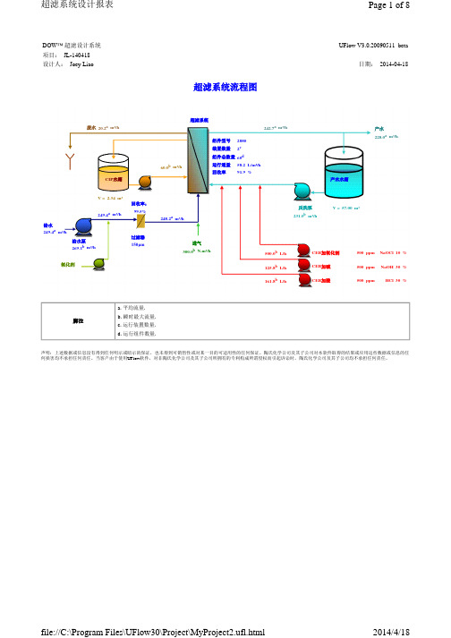
25s 100.0L/m²/h
40s 4.0m³/h
30min 58.2L/m²/h
声明:上述数据或信息没有得到任何明示或暗示的保证,也未得到可销售性或对某一目的可适用性的任何保证。陶氏化学公司及其子公司对本软件取得的结果或应用这些数据或信息的任 何损害均不承担任何责任。当客户由于使用UFlow软件,对非陶氏化学公司及其子公司所拥有的专利构成所谓侵权而引起诉讼时,陶氏化学公司及其子公司均不承担任何责任。
file://C:\Program Files\UFlow30\Project\MyProject2.ufl.html
2014/4/18
超滤系统设计报表
Page 5 of 8
CEB
状态
运行
化学加强反洗(CEB)
返回到运行b
运行步骤
步序
1 运行
2 进气
3 排水
4 反洗 1
5
6
反洗 2 浸泡
7 进气
8 排水
CEB加氧化剂 CEB加碱 CEB加酸
500 ppm NaOCl 10 % 500 ppm NaOH 30 % 500 ppm HCl 30 %
脚注
a. 平均流量. b. 瞬时最大流量. c. 运行装置数量. d. 运行组件数量.
声明:上述数据或信息没有得到任何明示或暗示的保证,也未得到可销售性或对某一目的可适用性的任何保证。陶氏化学公司及其子公司对本软件取得的结果或应用这些数据或信息的任 何损害均不承担任何责任。当客户由于使用UFlow软件,对非陶氏化学公司及其子公司所拥有的专利构成所谓侵权而引起诉讼时,陶氏化学公司及其子公司均不承担任何责任。
科思创厚膜陶瓷基板设计指南说明书
If a substrate design does not comply with these guidelines, CoorsTek may still be able to offer options to specific design
Spray Dried Alumina Powder
Feed Hopper
Premium ≤ 0.002 in./in. (≤ 0.002 mm/mm)
Tooled Corner Radius
Minimum 0.125" (3.175 mm) Radius required.
Thicknesses CoorsTek offers thicknesses from 0.015" (0.381 mm) to 0.100" (2.54 mm). The most economical thickness range is 0.025" (0.635 mm) to 0.040" (1.016 mm). Common form factors are for ADS-96R only. Other materials may have specific form factor constraints.
None > 0.001" (0.025 mm) High
None > 0.0007" (0.017 mm) Deep
None > 0.010” (0.254 mm) High
—
Байду номын сангаас
Bumps or Ridges Protrusions on the surface
Chips Open: Material broken off along an edge or corner Closed: Material has not broken off or separated
- 1、下载文档前请自行甄别文档内容的完整性,平台不提供额外的编辑、内容补充、找答案等附加服务。
- 2、"仅部分预览"的文档,不可在线预览部分如存在完整性等问题,可反馈申请退款(可完整预览的文档不适用该条件!)。
- 3、如文档侵犯您的权益,请联系客服反馈,我们会尽快为您处理(人工客服工作时间:9:00-18:30)。
UFLOW 2.2设 计 说 明DESIGN NOTESByFred YuOMEX R&D CenterOMEX Environmental Engineering Co., Ltd OMEX September 2008目 录第1章系统规模 (1)1.1概述 (1)1.2求解过程和算法 (1)1.3详细计算公式 (2)1.3.1组件数量计算 (2)1.3.2一天内每个步序运行时间 (3)1.3.3流量计算 (14)第2章化学药剂 (22)2.1概述 (22)2.2每天药剂消耗量 (22)2.2.1参数表 (22)2.2.2进水加酸 (22)2.2.3进水加絮凝剂 (23)2.2.4进水加氧化剂 (23)2.2.5反洗加氧化剂 (23)2.2.6CEB加酸 (24)2.2.7CEB加碱 (24)2.2.8CEB加氧化剂 (24)2.2.9CIP加酸 (25)2.2.10CIP加碱 (25)2.2.11CIP加氧化剂 (25)2.2.12每天化学药剂总消耗量 (26)2.3每天药剂消耗费用 (26)2.3.1输入输出参数表 (26)2.3.2每天酸消耗费用 (26)2.3.3每天碱消耗费用 (27)2.3.4每天氧化剂消耗费用 (27)2.3.5每天絮凝剂消耗费用 (27)2.3.6每天药剂消耗总费用 (27)2.4计量泵尺寸 (28)2.4.1参数表 (28)2.4.2进水酸计量泵 (28)2.4.3进水絮凝剂计量泵 (28)2.4.4进水氧化剂计量泵 (29)2.4.5反洗氧化剂计量泵 (29)2.4.6CEB酸计量泵 (29)2.4.7CEB碱计量泵 (30)2.4.8CEB氧化剂计量泵 (30)2.5计量箱、清洗水箱、产水箱尺寸 (30)2.5.1参数表 (30)2.5.2进水酸计量箱 (31)2.5.3进水絮凝剂计量箱 (31)2.5.4进水氧化剂计量箱 (31)2.5.5反洗氧化剂计量箱 (32)2.5.6CEB酸计量箱 (32)2.5.7CEB碱计量箱 (32)2.5.8CEB氧化剂计量箱 (32)2.5.9CIP清洗水箱 (33)2.5.10超滤产水水箱 (33)第3章能耗 (34)3.1概述 (34)3.2跨膜压差(TMP)计算 (34)3.2.1恒流过滤模式 (34)3.2.2恒压过滤模式 (34)3.3能耗计算 (35)3.3.1CIP清洗水箱加热 (35)3.3.2空气压缩机 (36)3.3.3自动阀门 (36)3.3.4仪表及PLC (37)3.3.5进水泵 (37)3.3.6反洗泵 (38)3.3.7清洗泵(酸泵或碱泵) (40)3.4能耗运行费用 (40)第1章系统规模1.1概述设计一个新的超滤系统时,首先需要确定系统规模,包括组件总数量、装置数量和单套装置组件数量,从而满足用户对系统产水量的要求。
1.2求解过程和算法过程分为两种情况:第一种情况,已知超滤系统平均进水流量,a) 根据设计平均进水流量和设计膜过滤通量估算出组件总数量;(参考1.3.1,公式中流量在这指平均进水流量,运行装置数量按1计算。
)b) 计算1天内每个步序运行时间;(参考1.3.2)c) 进行流量计算;(参考1.3.3)d) 把设计平均进水流量减去平均正洗流量1,推算出系统平均产水流量;(参考1.3.3.3)e) 根据系统平均产水流量和步序运行时间,推算出系统瞬时最大产水流量,即所有装置同时运行时过滤流量;(参考1.3.3.3)f) 根据瞬时最大产水流量和设计膜过滤通量,修正组件总数量;(参考1.3.1,公式中流量在这指最大产水流量,运行装置数量按1计算。
)g) 再次进行流量计算,把系统进水流量平均值与设计平均进水流量进行比较,如果误差在允许范围内则完成计算,否则返回到d步;(流量计算参考1.3.3)h) 根据组件总数量,罗列出组件布置方案,包括单套装置组件数量和装置数量;i) 确认装置数量、单套装置组件数量和备用装置数量;j) 修正过滤通量。
第二种情况,已知系统设计净产水流量,a) 根据系统设计净产水流量和设计膜过滤通量估算出组件总数量;(参考1.3.1,公式中流量在这指设计净产水流量,装置数量按1计算。
)b) 计算1天内每个步序运行时间;(参考1.3.2)c) 进行流量计算;(参考1.3.3)d) 把设计净产水流量加上反洗和CEB化学清洗水量,推算出系统平均产水流量;(参考1.3.3.3)e) 根据系统平均产水流量和步序运行时间,推算出系统瞬时最大产水流量,即所有装置同时运行时过滤流量;(参考1.3.3.3)f) 根据瞬时最大产水流量和设计膜过滤通量,修正组件总数量;(参考1.3.1,公式中流量在这指最大产水流量,运行装置数量按1计算。
)g) 再次进行流量计算,把平均净产水流量计算值与设计净产水流量进行比较,如果误差在允许范围内则完成计算,否则返回到d步;(流量计算参考1.3.3)h) 根据组件总数量,罗列出组件布置方案,包括单套装置组件数量和装置数量;i) 确认装置数量、单套装置组件数量和备用装置数量;j) 修正过滤通量。
1.3详细计算公式1.3.1组件数量计算1.3.1.1参数表输入参数符号输出参数符号组件总数量 N 流量 F1设计膜过滤通量 F2运行组件总数量 N1装置总数量 N2 单只组件膜面积 A运行装置数量 N3 -- ---- --备用装置数量 N4单套装置组件数量 N5-- --1.3.1.2运行组件总数量N1 = F1 / (F2·A)N1 ―运行组件总数量;F1 ―流量,m3/hr;F2 ―设计膜过滤通量,LMH;A ―单只组件膜面积,m2。
1.3.1.3单套装置组件数量N5 = N1 / N3N5 ―单套装置组件数量;N1 ―运行组件总数量;N3 ―运行装置数量。
1.3.1.4运行装置数量N3 = N1 / N5N3―运行装置数量;N1 ―运行组件总数量;N5 ―单套装置组件数量。
1.3.1.5装置总数量N2 = N3 + N4N2 ―装置总数量;N3―运行装置数量;N4 ―备用装置数量。
1.3.1.6组件总数量N = N5·N2N ―组件总数量;N5 ―单套装置组件数量;N2 ―装置总数量。
1.3.2一天内每个步序运行时间1.3.2.1参数表输入参数符号输出参数符号反洗频率F BW每天CEB酸洗时间T CEB1气擦洗频率F AIR每天CEB碱洗时间T CEB2CEB酸洗频率F CEB1每天常规反洗时间T REGULAR BW CEB碱洗频率F CEB2每天CIP清洗时间T CIP per Day 进气时间T AIR每天过滤时间T FILTER排放时间T DRAIN 反洗1时间T BW1所有装置每天清洗时间总和T CLEAN反洗2时间T BW2同时反洗装置数量N BW正洗时间T FF -- -- CEB药剂浸泡时间T SOAK -- -- CEB漂洗时间T RINSE -- --阀门开关时间T VALVE -- -- CIP清洗频率F CIP -- -- CIP清洗时间T CIP -- --1.3.2.2单只组件每天CEB酸洗时间T CEB1 = (T AIR + T DRAIN + T BW1 + T BW2 + T SOAK + T FF + T RINSE + T VALVE)·24 / F CEB1T CEB1―每天CEB酸洗时间,分钟;T AIR―进气时间,分钟;T DRAIN―排放时间,分钟;T BW1―反洗1时间,分钟;T BW2―反洗2时间,分钟;T SOAK― CEB药剂浸泡时间,分钟;T FF―正洗时间,分钟;T RINSE― CEB漂洗时间,分钟;T VALVE―阀门开关时间,分钟;24 ―时间换算系数,1天等于24小时;F CEB1― CEB酸洗频率,小时。
其中包括:每天CEB1气擦洗时间:T AIR CEB1 = T AIR·24 / F CEB1T AIR CEB1―每天CEB1气擦洗时间,分钟;T AIR―进气时间,分钟;24 ―时间换算系数,1天等于24小时;F CEB1― CEB酸洗频率,小时。
每天CEB1排水时间:T DRAIN CEB1 = T DRAIN·24 / F CEB1T DRAIN CEB1―每天CEB1排水时间,分钟;T DRAIN―排放时间,分钟;24 ―时间换算系数,1天等于24小时;F CEB1― CEB酸洗频率,小时。
每天CEB1药剂投加时间:T BW CEB1 = (T BW1 + T BW2)·24 / F CEB1 T BW CEB1―每天CEB1药剂投加时间,分钟;T BW1―反洗1时间,分钟;T BW2―反洗2时间,分钟;24 ―时间换算系数,1天等于24小时;F CEB1― CEB酸洗频率,小时。
每天CEB1浸泡时间:T SOAK CEB1 = T SOAK·24 / F CEB1T SOAK CEB1―每天CEB1浸泡时间,分钟;T SOAK― CEB药剂浸泡时间,分钟;24 ―时间换算系数,1天等于24小时;F CEB1― CEB酸洗频率,小时。
每天CEB1正洗时间:T FF CEB1 = T FF·24 / F CEB1T FF CEB1―每天CEB1正洗时间,分钟;T FF―正洗时间,分钟;24 ―时间换算系数,1天等于24小时;F CEB1― CEB酸洗频率,小时。
每天CEB1漂洗时间:T RINSE CEB1 = T RINSE·24 / F CEB1T RINSE CEB1―每天CEB1漂洗时间,分钟;T RINSE― CEB漂洗时间,分钟;24 ―时间换算系数,1天等于24小时;F CEB1― CEB酸洗频率,小时。
每天CEB1阀门动作时间:T VALVE CEB1 = T VALVE·24 / F CEB1T VALVE CEB1―每天CEB1阀门动作时间,分钟;T VALVE―阀门开关时间,分钟;24 ―时间换算系数,1天等于24小时;F CEB1― CEB酸洗频率,小时。
注:CEB步序参照图1.1。
第1章 系统规模 U-Flow 2.2 设计说明 7DOW CONFIDENTIAL - Do not share without permission 图1.1 CEB运行步序表1.3.2.3单只组件每天CEB碱洗时间T CEB2 = (T AIR + T DRAIN + T BW1 + T BW2 + T SOAK + T FF + T RINSE + T VALVE)·24 / F CEB2 T CEB2―每天CEB碱洗时间,分钟;T AIR―进气时间,分钟;T DRAIN―排放时间,分钟;T BW1―反洗1时间,分钟;T BW2―反洗2时间,分钟;T SOAK― CEB药剂浸泡时间,分钟;T FF―正洗时间,分钟;T RINSE― CEB漂洗时间,分钟;T VALVE―阀门开关时间,分钟;24 ―时间换算系数,1天等于24小时;F CEB2― CEB碱洗频率,小时。