RC4207GN中文资料
深圳天诚巨能科技有限公司锂锰扣式电池产品规格书说明书

锂锰扣式电池产品规格书电池型号:CR2025签名时间编制审核批准供货商:深圳天诚巨能科技有限公司地址:广东省深圳市宝安区西乡银田工业区A6栋5楼电话:86-0755-2936766929367589传真:86-0755-********1.目的1.1对深圳天诚巨能科技有限公司出品的锂电池的产品规格、测试方法进行规范,避免因测试条件、方法的不同引起偏差。
1.2指导客户正确选择和使用我公司电池。
2.产品类别和产品型号表1类别型号锂锰扣式电池CR20253.技术参数表2序项目特性号1标称容量150mAh(23±3℃时15KΩ负载电阻连续放电至2.0V)2标称电压3V3工作温度范围-20~+60℃4年自放电率≤3%5最大脉冲电流*17mA6最大连续放电电流*5mA7最大外形尺寸直径20mm,高度2.5mm8结构及成分二氧化锰正极、锂负极、有机电液、隔膜及不锈铁外壳等9重量约2.4g*最大脉冲电流指在23℃的环境下,放电40%的电池接上负载,15秒后,电池的负载电压高于2.0V所对应的最大电流。
*最大连续放电电流指在23℃的环境下,将电池用恒定电流持续放电至2.0V,获得标称容量的50%所对应的最大电流。
4.性能及测试方法4.1基本性能表3序号项目标准测试方法1外形尺寸直径20.0mm,高度2.5mm 用精度不低于0.02mm的游标卡尺或具有同等精度的量具测量。
2外观电池表面应光洁、无碰伤、变形且标志清晰、无漏液。
目视检查。
3开路电压 3.0~3.5V 电池在23℃±3℃、湿度45%~75%下放置24h 以上, 在同一环境下用直流电压表进行测量。
4放电容量150mAH 测试的样品电池应在23℃±3℃、湿度45%~75%下放置24h以上,在同一环境下串联15kΩ负载电阻连续放电至2.0V终止。
5极端具有良好的导电性能,无漏液、锈蚀现象。
目视检查。
6温度特性低温放电额定容量的60%在环境温度为-20℃±2℃条件下,串联15kΩ负载电阻连续放电至2.0V终止。
AQZ207中文资料
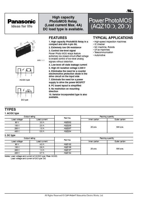
VL
60 V
100 V 200 V 400 V
Output
Continuous load current (DC) Peak load current
IL
4.0 A
2.6 A
1.3 A
0.7 A
I peak
9.0 A
6.0 A
3.0 A
1.5 A
Power dissipation
Pout
1.35 W
All Rights Reserved © COPYRIGHT Matsushita Electric Works, Ltd.
元器件交易网
Power PhotoMOS (AQZ10❍, 20❍)
2. DC type 1) Absolute maximum ratings (Ambient temperature: 25°C 77°F)
Remarks f = 100 Hz, Duty factor = 0.1% 100 ms (1 shot), VL = DC Non-condensing at low temperatures
2) Electrical characteristics (Ambient temperature: 25°C 77°F)
Item
Symbol AQZ102 AQZ105 AQZ107 AQZ104
Condition
LED operate current
Typical IFon
Maximum
1.0 mA 3.0 mA
IL= 100 mA VL= 10 V
Input
LED turn off current
Minimum IFoff
Typical
F40UP20DN中文资料

FFAF40UP20DN Ultrafast Recovery Power RectifierFFAF40UP20DN Ultrafast Recovery Power RectifierFFAF40UP20DN Ultrafast Recovery Power RectifierTRADEMARKSThe following are registered and unregistered trademarks Fairchild Semiconductor owns or is authorized to use and is not intended to be an exhaustive list of all such trademarks.DISCLAIMERFAIRCHILD SEMICONDUCTOR RESERVES THE RIGHT TO MAKE CHANGES WITHOUT FURTHER NOTICE TO ANY PRODUCTS HEREIN TO IMPROVE RELIABILITY, FUNCTION OR DESIGN. FAIRCHILD DOES NOT ASSUME ANY LIABILITY ARISING OUT OF THE APPLICATION OR USE OF ANY PRODUCT OR CIRCUIT DESCRIBED HEREIN; NEITHER DOES IT CONVEY ANY LICENSE UNDER ITS PATENT RIGHTS, NOR THE RIGHTS OF OTHERS.LIFE SUPPORT POLICYFAIRCHILD’S PRODUCTS ARE NOT AUTHORIZED FOR USE AS CRITICAL COMPONENTS IN LIFE SUPPORT DEVICES OR SYSTEMS WITHOUT THE EXPRESS WRITTEN APPROVAL OF FAIRCHILD SEMICONDUCTOR CORPORATION.As used herein:1. Life support devices or systems are devices or systems which,(a) are intended for surgical implant into the body, or (b) support or sustain life, or (c) whose failure to perform when properly used in accordance with instructions for use provided in the labeling,can be reasonably expected to result in significant injury to the user.2. A critical component is any component of a life support device or system whose failure to perform can be reasonably expected to cause the failure of the life support device or system, or to affect its safety or effectiveness.PRODUCT STATUS DEFINITIONS Definition of TermsDatasheet Identification Product Status DefinitionAdvance InformationFormative or In Design This datasheet contains the design specifications for product development. Specifications may change in any manner without notice.PreliminaryFirst ProductionThis datasheet contains preliminary data, andsupplementary data will be published at a later date.Fairchild Semiconductor reserves the right to make changes at any time without notice in order to improve design.No Identification Needed Full ProductionThis datasheet contains final specifications. Fairchild Semiconductor reserves the right to make changes at any time without notice in order to improve design.Obsolete Not In ProductionThis datasheet contains specifications on a product that has been discontinued by Fairchild semiconductor.The datasheet is printed for reference information only.FAST ®FASTr™FPS™FRFET™GlobalOptoisolator™GTO™HiSeC™I 2C™i-Lo ™ImpliedDisconnect™IntelliMAX™ISOPLANAR™LittleFET™MICROCOUPLER™MicroFET™MicroPak™MICROWIRE™MSX™MSXPro™OCX™OCXPro™OPTOLOGIC ®OPTOPLANAR™PACMAN™POP™Power247™PowerEdge™PowerSaver™PowerTrench ®QFET ®QS™QT Optoelectronics™Quiet Series™RapidConfigure™RapidConnect™µSerDes™Scalar Pump™SILENT SWITCHER ®SMART START™SPM™Stealth™SuperFET™SuperSOT™-3SuperSOT™-6SuperSOT™-8SyncFET™TCM™TinyLogic ®TINYOPTO™TruTranslation™UHC™UltraFET ®UniFET™VCX™Wire™A CEx™ActiveArray™Bottomless™Build it Now™CoolFET™CROSSVOLT ™DOME™EcoSPARK™E 2CMOS™EnSigna™FACT™FACT Quiet Series™Across the board. Around the world.™The Power Franchise ®Programmable Active Droop™Rev. I18。
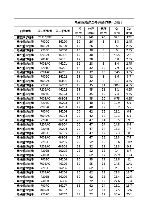
角接触球轴承型号参数对照表
17 17 21 15 15 18 18 18 23 27 16 16 19 19 19 25 16 16 20 20 20 27 31 18 18 21 21 21 29 18 18 22 22 22 31 35 18 18 23 23 23
28.1 25.6 32.5 20.5 18.7 36.4 33.6 30.6 39.7 64.9 24.4 22.2 40.8 37.7 34.3 50.6 26 23.6 42.8 39.4 37.535.7 64.4 90.2 34.1 31.1 52.9 48.7 44.1 74.3 35 31.9 64 58.9 53.4 84.9 119 37.1 33.7 73.1 67.3 60.9
66313 36114 46114 36214 46214 66214 66314 36115 46115 36215 46215 66215 36116 46116 36216 46216 66216 66316 36117 46117 36217 46217 66217 66317 36118 46118 36218 46218 66218 66318 36119 46119 36219 46219 66219 66319 36120 4612O 36220 46220
角接触球轴承型号参数对照表(众悦) 轴承类型 螺旋滚子轴承 角接触球轴承 角接触球轴承 角接触球轴承 角接触球轴承 角接触球轴承 角接触球轴承 角接触球轴承 角接触球轴承 角接触球轴承 角接触球轴承 角接触球轴承 角接触球轴承 角接触球轴承 角接触球轴承 角接触球轴承 角接触球轴承 角接触球轴承 角接触球轴承 角接触球轴承 角接触球轴承 角接触球轴承 角接触球轴承 角接触球轴承 角接触球轴承 角接触球轴承 角接触球轴承 角接触球轴承 角接触球轴承 角接触球轴承 角接触球轴承 角接触球轴承 角接触球轴承 角接触球轴承 角接触球轴承 角接触球轴承 角接触球轴承 国内新型号 7921C/DT 7000C 7000AC 7200C 7200AC 7001C 7001AC 7201C 7201AC 7002C 7002AC 7202C 7202AC 7003C 7003AC 7203C 7203AC 7004C 7004AC 7204C 7204AC 7204B 7005C 7005AC 7205C 7205AC 7205B 7305B 7006C 7006AC 7206C 7206AC 7206B 7306B 7007C 7007AC 7207C 国内旧型号 36100 46100 36200 462O0 36101 46101 36201 46201 36102 461O2 36202 46202 36103 461O3 36203 46203 36104 46104 36204 462O4 66204 36105 461O5 36205 462O5 66205 66305 36106 46106 36206 46206 66206 66306 36107 46107 36207 内径 (mm) 105 10 10 10 10 12 12 12 12 15 15 15 15 17 17 17 17 20 20 20 20 20 25 25 25 25 25 25 30 30 30 30 30 30 35 35 35 外径 (mm) 145 26 26 30 30 28 28 32 32 32 32 35 35 35 35 40 40 42 42 47 47 47 47 47 52 52 52 62 55 55 62 62 62 72 62 62 72 宽度 (mm) 40 8 8 9 9 8 8 10 10 9 9 11 11 10 10 12 12 12 12 14 14 14 12 12 15 15 15 17 13 13 16 16 16 19 14 14 17 Cr (kN) 92.1 5.3 5 5 4.65 5.8 5.4 7.9 7.45 6.6 6.1 8065 8.1 7.3 6.75 10.9 10.2 11.1 10.3 15.5 14.5 13.3 12.3 11.3 16.6 15.3 14 22.9 15.8 14.5 23 21.3 19.4 27.6 19.1 17.5 30.4 Cor (kN) 123 2.45 2.35 2.35 2.2 2.95 2.75 3.85 3.65 3.7 3.45 4.55 4.25 4.45 4.15 5.9 5.5 6.6 6.1 9 8.4 7.7 8 7.4 10.2 9.5 8.7 13.3 11 10.1 14.7 13.7 12.5 17.4 13.7 12.6 20.1
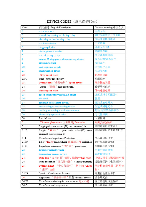
IEEE标准中综保数字代码的含义
63
Penstock Pressure Low Trip
变压器压力释放保护
63-1
Buchholz“巴克奥斯”relay / Alarm (BAL)
气体继电器/报警
63-2
Buchholz relay / Trip (BTR)
气体继电器(瓦斯)/跳闸
63R
Pressure relief relay
励磁继电器
57
short-circuiting or grounding device
短路或接地元件
58
rectification“2特菲克特申”failure relay
整流故障继电器
586A
Line Trip Circuit 1
线路跳闸回路1
586B
Line Trip Circuit 2
线路跳闸回路2
复合电压闭锁过流保护
52
ACcircuit breaker
交流断路器
53
exciter orDCgenerator relay
励磁机或直流发电机继电
54
turning gear engaging device
盘车装置啮合元件
55
power factor relay
功率因数继电器
56
field application relay
同步转速装置
14
Rotor“饶特”plug protection
转子堵转保护
14
Under speed relay
低转速继电器
15
speed or frequency matching device
速度或频率匹配元件
轴承代号含义说明之欧阳歌谷创编

轴承代号含义说明欧阳歌谷(2021.02.01)轴承代号由基本代号,前置代号和后置代号构成。
基本代号表示轴承系列及尺寸,前置代号表示轴承类型及轴承零件,位于基本代号之前,后置代号表示轴承的结构,保持架,密封与防尘,公差,油隙,热处理等技术要求,位于基本代号之后。
1.前置代号C- 圆柱滚子轴承附件(或轴承本身),例:C00210 45C- 成对安装圆锥滚子轴承,面对面安装,例:45C30210 46C- 成对安装圆锥滚子轴承,背对背安装,例:46C30210 4CRI- 四列圆柱滚子轴承内圈,例:4CRI4560F 4CRO- 四列圆柱滚子轴承外圈,例:4CRO660AF E- 磁电机球轴承,外径为正公差,例:E10 EN- 磁电机球轴承,外径为负公差,例:EN10 IR- 滚针轴承内圈(英制),例:IR1212 IRA- 滚针轴承内圈,比IR系列宽(英制),例:IRA20 IRM- 滚针轴承内圈,例:IRM710 M- 最大载荷容量型球轴承,例:M6311 OR- 滚针轴承,只有外圈,例:OR10876 F- 深沟球轴承带凸缘,例:F603 TR- 尺寸非标准的单列圆锥滚子轴承,例:TR060702W- 宽型,深沟球轴承,例:W602ZZX2.后置代号(1)内部结构A- 角接触轴承,接触角30度(不标出),例:7210 B- 角接触轴承,接触角40度,例:7210B C- 角接触轴承,接触角15度,例:7210C C- 圆锥滚子轴承,接触角20度,例:30303C D- 圆锥滚子轴承,接触角28度30分,例:30305D G- 压缩轴向油隙的调心和圆锥滚子轴承J- 圆锥滚子轴承,符合ISO分组,例:30206J N- 圆锥滚子轴承,特殊噪声要求,例:30208N R- 加大负荷容量的调心,圆锥和圆柱滚子轴承,例:22228R (2)密封和防尘OR- 球轴承带O型密封圈,例:6201+OR RK- 单面,双唇接触式合成橡胶密封,例:6210RK 2RK- 双面,双唇接触式合成橡胶密封,例:6210.2RK RS- 单面,接触式合成橡胶密封,例:6210RS 2RS- 双面,接触式合成橡胶密封,例:6210-2RS RSA- 单面,带金属罩接触式合成橡胶密封,例:88107RSA 2RSA- 双面,带金属罩接触式合成橡胶密封,例:88107-2RSA RSB- 单面,带加卡金属罩的接触式合成橡胶密封,例:88107RSB2RSB- 双面,带加卡金属罩的接触式合成橡胶密封,例:88107-2RSBRSC- 硅橡胶制RS型密封,例:6210RSCRSD- 聚丙烯橡胶制RS型密封,例:6210RSD RSE- 单面,挡边引导接触式合成橡胶密封,例:6206RSE 2RSE- 双面,挡边引导接触式合成橡胶密封,例:6206-2RSE RSF- RS型氟化橡胶密封,例:6210RSF RU- 单面,非接触式合成橡胶密封,例:6205RU 2RU- 双面,非接触式合成橡胶密封,例:6205-2RU TR- 单面,三唇金属罩合成橡胶密封,例:4508B-TR 2TR- 双面,三唇金属罩合成橡胶密封,例:4508B-2TR U- 一面带接触式合成橡胶密封的滚针轴承,例:NA4916U UU- 二面带接触式合成橡胶密封的滚针轴承,例:NA4916UU Z- 单面钢制防尘盖,例:6205.Z ZZ- 双面钢制防尘盖,例:6205ZZ ZL- 单面,L型内径的钢制防尘盖,例:6207ZL ZX- 单面,由止动环压紧的钢制防尘盖,例:6205ZX ZXL- 由止动环压紧L型内径单面钢制防尘盖,例:6203ZXL ZZL- 钢制防尘盖,双面,L型内径,例:6203ZZL ZZX- 钢制防尘盖,双面,由止动环压紧,例:605ZZX ZZXL- 钢制防尘盖,双面,由止动环压紧,L型内径,例:6303ZZXL(3)套圈形状a- 大于标准倒角的非标准倒角,例:6205aB- 圆锥滚子轴承,外圈带凸缘,例:30210B BI- 双半内圈球轴承,例:6215BI BO- 双半外圈球轴承,例:6215BO D- 圆锥滚子轴承,双外圈或双内圈(英制),例:594/592D K- 带锥孔轴承,锥度为1:12,例:1210K K30- 带锥孔轴承,锥度为1:30,例:23026K30 N- 外圈带止动槽轴承,例:6206N C- 带锁孔的圆锥滚子轴承NR- 外圈带止动环轴承,例:6210NR Y- 小于标准倒角尺寸的非标准倒角,例:30206Y S- 圆锥滚子轴承,非标准倒角(斜倒角)SG- 内径带螺旋槽的圆锥滚子轴承T- 锥孔或锥形外径(英制)圆锥滚子轴承TD- 双列、锥孔或锥形外径(英制)圆锥滚子轴承W- 双内圈、端面带槽的圆锥滚子轴承,例:47T694625WH W- 外圈有润滑油沟槽和孔的圆柱滚子轴承,例:NU316W Wi- 圆柱滚子轴承(1-外圈有润滑油孔;2-内圈有润滑油孔和槽;3-内圈有润滑油孔;4-内、外圈有润滑油孔;5-内、外圈有润滑油孔和槽;6-外圈有润滑油孔和槽,内圈有润滑油孔;10-外圈带锁孔;11-外圈带润滑油孔和锁孔;13-外圈带锁孔,内圈带润滑油孔;14-内圈带润滑油孔,外圈带润滑油孔和锁孔;I=1,2,…)。
RC4194资料

PRODUCT SPECIFICATION RC41942RC4194PRODUCT SPECIFICATION3Operating ConditionsElectrical Characteristics(±5 £ V OUT £ V MAX ; –V IN £ -8V; I L = ±1mA; RM4194: -55°C £ T j £ +125°C; RC4194: 0°C £ T j £ +70°C unless otherwise specified)Notes:1.Measured as (mA)2. Output voltage temperature drift guaranteed by design.3. The current drain will increase by 50m A/V OUT on positive side and 100m A/V OUT on negative side.4. The specifications above apply for the given junction temperatures since pulse test conditions are used.Parameter MinTyp MaxUnits q JC Thermal Resistance CerDIP60°C/W TO-66 Metal Can 7°C/W q JAThermal ResistancePDIP 160°C/W CerDIP120°C/W TO-66 Metal Can42°C/WParameters Test ConditionsMinTyp Max Units Line Regulation D V S = 0.1 V IN 0.040.1%V OUT Load Regulation 14194K: I L < 200 mA 4194D: I L < 100 mA ±V S = ± (V OUT + 5)V0.0020.004%V OUT /I L (mA)Output Voltage Drift With Temperature 2 Positive Output V OUT = ±5V 0.0020.015%/°C Negative Output V OUT = ±5V0.0030.015%/°C Supply Current 3 (Positive)V S = ±V MAX , V OUT = 0V, I L = 0 mA+0.8+2.5mA Supply Current 4 (Negative)V S = ±V MAX , V OUT = 0V, I L = 0 mA -1.8-4.0mA Supply VoltageRM4194±9.5±45V RC4194±9.5±35V Output Voltage Scale Factor R SET = 71.5 k W , T j = +25°C, V S = ±V MAX2.38 2.52.62k W /V Output Voltage RangeRM4194: R SET = 71.5 k W , I L = 25 mA0.05±42V RC4194: R SET = 71.5 k W , I L = 25 mA0.05±42V Output Voltage Tracking ±0.4±2.0%Ripple RejectionF = 120 Hz, T j = +25°C 70dB Input-Output Voltage Differential I L = 50 mA, T j = +25°C 3.0V Short Circuit Current V S = ±30V, T j = +25°C 300mA Output Noise Voltage C L = 4.7 m F, V OUT = ±15V,F = 10 Hz to 100 kHz250m V RMS Internal Thermal Shutdown175°CD V OUTV OUT ------------------100%´èøæöI L §PRODUCT SPECIFICATIONRC41944Typical Performance CharacteristicsFigure 1. Ripple Rejection vs. Frequency Figure 2. Load Regulation vs. Load CurrentFigure 3. Output Voltage Tracking vs. TemperatureRC4194PRODUCT SPECIFICATION5PRODUCT SPECIFICATION RC4194 Typical Applications (continued)Figure 6. Balanced Output Voltage — Op Amp ApplicationFigure 7. Digitally Controlled Dual 200 mA Voltage Regulator6RC4194PRODUCT SPECIFICATION7PRODUCT SPECIFICATION RC41948RC4194PRODUCT SPECIFICATION9PRODUCT SPECIFICATIONRC419410Table 1. Commercial Heatsink Selection GuideNo attempt has been made to provide a complete list of all heatsink manufacturers. This list is only representative.Staver Co., Inc.: 41-51 N Saxon Ave., Bay Shore, NY 11706IERC: 135 W Magnolia Blvd., Burbank, CA 91502Thermalloy: P.O. Box 34829, 2021 W Valley View Ln., Dallas, TX Wakefield Engin Ind: Wakefield, MA 01880* All values are typical as given by manufacturer or as determined from characteristic curves supplied by manufacturer.q S-A 1(°C/W)Manufacturer/Series or Part Number TO-66 Package0.31 – 1.0Thermalloy — 6441, 6443, 6450, 6470, 6560, 6590, 6660, 66901.0 – 3.0Wakefield — 641Thermalloy — 6123, 6135, 6169, 6306, 6401, 6403, 6421, 6423, 6427, 6442, 6463, 65003.0 – 5.0Wakefield — 621, 623Thermalloy — 6606, 6129, 6141, 6303IERC — HP Staver — V3-3-25.0 – 7.0Wakefield — 690Thermalloy — 6002, 6003, 6004, 6005, 6052, 6053, 6054, 6176, 6301IERC — LB Staver— V3-5-27.0 – 10.0Wakefield — 672Thermalloy — 6001, 6016, 6051, 6105, 6601IERC — LA, uPStaver — V1-3, V1-5, V3-3, V3-5, V3-710.0 – 25.0Thermalloy — 6-13, 6014, 6015, 6103, 6104, 6105, 6117Dual In-line Package20Thermalloy — 600730Thermalloy — 601032Thermalloy — 601134Thermalloy — 601245IERC — LI60Wakefield — 650, 651In the above example, let’s say that the user’s load current is 200 mA and he wants to calculate the combined q C-S and q S-A he needs:Given: I O = 200 mA,= 11.75°C/WGiven q J-C = 7.15°C/W for the 4194 in the K package,q C-S + q S-A = 11.75°C/W – 7.15°C/W = 4.6°C/WWhen using heatsink compound with a metal-to-metal interface, a typical q C-S = 0.5°C/W for the K package. The remaining q S-A of approximately 4°C/W is a largeenough thermal resistance to be easily provided by a number of heatsinks currently available. Table 1 is a brief selection guide to heatsink manufacturers.q J A –T J T A–V IN V OUT –()I O V IN I Q ´+´---------------------------------------------------------------------------=50°C 125°C–10V 200mA ´40+ 3.25103–´´---------------------------------------------------------------------------------=元器件交易网RC4194PRODUCT SPECIFICATIONPRODUCT SPECIFICATION RC4194 Mechanical Dimensions9-Lead Metal Can IC Header PackageRC4194PRODUCT SPECIFICATIONMechanical Dimensions (continued) 14-Lead Plastic DIP PackageLIFE SUPPORT POLICYFAIRCHILD’S PRODUCTS ARE NOT AUTHORIZED FOR USE AS CRITICAL COMPONENTS IN LIFE SUPPORT DEVICES OR SYSTEMS WITHOUT THE EXPRESS WRITTEN APPROVAL OF THE PRESIDENT OF FAIRCHILD SEMICONDUCTOR CORPORATION. As used herein:1.Life support devices or systems are devices or systemswhich, (a) are intended for surgical implant into the body, or (b) support or sustain life, and (c) whose failure toperform when properly used in accordance withinstructions for use provided in the labeling, can bereasonably expected to result in a significant injury of the user.2. A critical component in any component of a life supportdevice or system whose failure to perform can bereasonably expected to cause the failure of the life support device or system, or to affect its safety or effectiveness.。
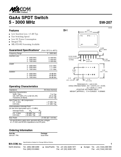
SW-207中文资料
Europe: Tel. +44 (1344) 869 595 Fax +44 (1344) 300 020
Specifications Subject to Change Without Notice.
M/A-COM, Inc.
North America: Tel. (800) 366-2266 Fax (800) 618-8883
s
1
Asia/Pacific: Tel. +81 (03) 3226-1671 Fax +81 (03) 3226-1451
(From -55°C to +85°C) 5 - 3000 MHz 5 - 3000 MHz 5 - 2000 MHz 5 - 1000 MHz 2.3 dB Max. 1.4 dB Max. 1.0 dB Max. 2.5:1 Max. 1.7:1 Max. 1.5:1 Max. 18 dB Min. 28 dB Min. 38 dB Min.
元器件交易网
GaAs SPDT Switch 5 - 3000 MHz
Features
q q q q q
SW-207
V2.00
DI-1
CTL
0.87 (22.1 0.5)
RF IN
Low Insertion Loss: 1.0 dB Typ. Fast Switching Speed Low DC Power Consumption Integral TTL MIL-STD-883 Screening Available
Schematic
Truth Table
Specifications Subject to Change Without Notice.
- 1、下载文档前请自行甄别文档内容的完整性,平台不提供额外的编辑、内容补充、找答案等附加服务。
- 2、"仅部分预览"的文档,不可在线预览部分如存在完整性等问题,可反馈申请退款(可完整预览的文档不适用该条件!)。
- 3、如文档侵犯您的权益,请联系客服反馈,我们会尽快为您处理(人工客服工作时间:9:00-18:30)。
PRODUCT SPECIFICATION RC4207
RC4207
PRODUCT SPECIFICATION
Electrical Characteristics
(V S = ±15V , and T A = +25°C unless otherwise noted)
Notes:
1.Long Term Input Offset Voltage Stability refers to the averaged trend line of V OS vs. Time over extended periods after the
first 30 days of operation. Excluding the initial hour of operation, changes in V OS during the first 30 operating days are typically 2.5 m V.
2.Guaranteed by design.
3.Input Offset Voltage measurements are performed by automated test equipment approximately 0.5 seconds after application
of power.
4.The input protection diodes do not allow the device to be removed or inserted into the circuit without first removing power.
4207F
4207G Parameters Test Conditions
Min
Typ Max Min
Typ Max Units Input Offset Voltage 33075
60150m V Long Term V OS Stability 10.20.5m V/Mo Input Offset Current ±0.5±5±2±10nA Input Bias Current ±0.5±5±2±10
nA Input Noise Voltage 0.1 Hz to 10 Hz 0.350.35m Vp-p
Input Noise Voltage Density
F O = 10 Hz 10.310.3F O = 100 Hz 1010F O = 1000 Hz
9.69.6Input Noise Current 0.1 Hz to 10 Hz 1414pA p-p
Input Noise Current Density
F O = 10 Hz 0.320.32F O = 100 Hz 0.140.14F O = 1000 Hz
0.120.12Input Resistance (Diff. Mode)6031M W Input Resistance (Com. Mode)200120G W Input Voltage Range 4
±11±14±11±14V Common Mode Rejection Ratio V CM = ±11V
10012694110dB Power Supply Rejection Ratio V S = ±4.0V to ±16.5V 10011094104dB Large Signal Voltage Gain
R L ³ 2k W , V OUT = ±10V 400600250400V/mV
V OUT = ±1.0V
R L = 1K W , V S = ±4.0V
200400100200Output Voltage Swing
R L ³ 10k W ±12.5±13±12.5±13V
R L ³ 2k W ±12±12.8±12±12.8R L ³ 1k W
±11±12±11±12Slew Rate
R L ³ 2k W 0.1
0.30.1
0.3V/m s Closed Loop Bandwidth A VOL = +1.0 1.5 1.5MHz Open Loop Output Resistance V OUT = 0, I OUT = 06060W Power Consumption V S = ±15V, R L = ¥150200160240mW V S = ±4.0V, R L = ¥3550
4864
Crosstalk
DC
126155
126155
dB nV Hz
-----------pA Hz -----------
PRODUCT SPECIFICATION
RC4207
Typical Performance Characteristics
Figure 1. Input Offset Voltage vs. Temperature
Figure 2. Input Bias Current vs. Differential Input Voltage
Figure 3. Input Bias Current vs. Temperature
Figure 4. Input Offset Current vs. Temperature
Figure 5. CMRR vs. Frequency
Figure 6. PSRR vs. Frequency
RC4207PRODUCT SPECIFICATION
PRODUCT SPECIFICATION
RC4207
Typical Performance Characteristics (continued)
Figure 12. Power Consumption vs. Total Supply Voltage
Figure 13. Output Short Circuit Current vs. Time
Typical Applications
Figure 14. Adjustment-Free Precision Summing Amplifier Figure 15. High Stability Thermocouple Amplifier
Figure 16. Precision Absolute Value Circuit
元器件交易网
RC4207PRODUCT SPECIFICATION
Mechanical Dimensions – 8-Lead Plastic DIP Package
LIFE SUPPORT POLICY
FAIRCHILD’S PRODUCTS ARE NOT AUTHORIZED FOR USE AS CRITICAL COMPONENTS IN LIFE SUPPORT DEVICES OR SYSTEMS WITHOUT THE EXPRESS WRITTEN APPROVAL OF THE PRESIDENT OF FAIRCHILD SEMICONDUCTOR CORPORATION. As used herein:
1.Life support devices or systems are devices or systems
which, (a) are intended for surgical implant into the body, or (b) support or sustain life, and (c) whose failure to
perform when properly used in accordance with
instructions for use provided in the labeling, can be
reasonably expected to result in a significant injury of the user.2. A critical component in any component of a life support
device or system whose failure to perform can be
reasonably expected to cause the failure of the life support device or system, or to affect its safety or effectiveness.。