会议系统培训CR-M3101
OM-USB-3101使用指南说明书
Table of ContentsPrefaceAbout this User's Guide (4)What you will learn from this user's guide (4)Conventions in this user's guide (4)Where to find more information (4)Chapter 1Introducing the OM-USB-3101 (5)Functional block diagram (5)Chapter 2Installing the OM-USB-3101 (6)What comes with your shipment? (6)Hardware (6)Software (6)Documentation (6)Unpacking (6)Installing the software (6)Installing the hardware (6)Calibrating the OM-USB-3101 (7)Chapter 3Functional Details (8)External components (8)USB connector (8)LED indicators (8)Screw terminals (8)Signal connections (9)Analog voltage outputs (9)Digital I/O (9)Synchronous DAC load (10)Counter input (10)Power output (10)Chapter 4Specifications (11)Analog voltage output (11)Analog output calibration (12)Digital input/output (12)Synchronous DAC Load (13)Counter (13)Memory (14)Microcontroller (14)Power (14)USB specifications (14)Environmental (14)Mechanical (14)Main connector and pinout (15)About this User's GuideWhat you will learn from this user's guideThis user's guide describes the Omega Engineering OM-USB-3101 data acquisition device and lists device specifications.Conventions in this user's guideCaution!Shaded caution statements present information to help you avoid injuring yourself and others, damaging your hardware, or losing your data.bold text Bold text is used for the names of objects on a screen, such as buttons, text boxes, and check boxes.italic text Italic text is used for the names of manuals and help topic titles, and to emphasize a word or phrase.Where to find more informationAdditional information about OM-USB-3101 hardware is available on our website at . You can also contact Omega Engineering by phone, fax, or email with specific questions.▪Phone: (203) 359-1660▪Fax: (203) 359-7700▪Email: *************Introducing the OM-USB-3101The OM-USB-3101 is a USB 2.0 full-speed device that is supported under popular Microsoft® Windows®operating systems. The OM-USB-3101 is fully compatible with both USB 1.1 and USB 2.0 ports.The OM-USB-3101 provides four channels of analog voltage output, eight digital I/O connections, and one 32-bit event counter.The OM-USB-3101 has a quad (4-channel) 16-bit digital-to-analog converter (DAC). You set the voltage output range of each DAC channel independently with software for either bipolar or unipolar. The bipolar range is ±10 V, and the unipolar range is 0 to 10 V. The analog outputs may be updated individually orsimultaneously. A bidirectional synchronization connection allows you to simultaneously update the DAC outputs on multiple devices.The OM-USB-3101 features eight bidirectional digital I/O connections. You can configure the DIO lines as input or output in one 8-bit port. All digital pins are floating by default. A screw terminal connection isprovided for pull-up (+5 V) or pull-down (0 volts) configuration.The 32-bit counter can count TTL pulses.The OM-USB-3101 is powered by the +5 volt USB supply from your computer. No external power is required.All I/O connections are made to screw terminals.Functional block diagramOM-USB-3101 functions are illustrated in the block diagram shown here.Figure 1. OM-USB-3101 block diagramInstalling the OM-USB-3101What comes with your shipment?The following items are shipped with the OM-USB-3101:Hardware▪OM-USB-3101▪USB cableSoftware▪Software for OMB-DAQ-2400, OM-USB, OM-WEB, and OM-WLS Series Data Acquisition Modules CD DocumentationIn addition to this hardware user's guide, you should also receive the OMB-DAQ-2400, OM-USB, OM-WEB, and OM-WLS Series Data Acquisition Software User's Guide. This booklet provides an overview of thesoftware you received with the device, and includes information about installing the software.UnpackingAs with any electronic device, take care while handling to avoid damage from static electricity. Beforeremoving the device from its packaging, ground yourself using a wrist strap or by simply touching the computer chassis or other grounded object to eliminate any stored static charge.If any components are missing or damaged, notify Omega Engineering immediately by phone, fax, or e-mail.▪Phone: (203) 359-1660▪Fax: (203) 359-7700▪Email: *************Installing the softwareRefer to the Software User's Guide for instructions on installing the software. This booklet ships with the hardware, and is available in PDF at /manuals/manualpdf/M4803.pdf.Installing the hardwareTo connect the OM-USB-3101 to your system, connect the USB cable to an available USB port on thecomputer or to an external USB hub connected to the computer. Connect the other end of the USB cable to the USB connector on the device. No external power is required.When connected for the first time, a Found New Hardware dialog opens when the operating system detects the device. When the dialog closes, the installation is complete. The LED on the OM-USB-3101 turns on after the device is successfully installed.OM-USB-3101 User's Guide Installing the OM-USB-3101Calibrating the OM-USB-3101The OM-USB-3101 is shipped fully calibrated. Calibration coefficients are stored in the device FLASHmemory. Return the device to Omega Engineering when calibration is required. The normal calibration interval is once per year.Chapter 3 Functional DetailsExternal componentsThe OM-USB-3101 has the following external components, as shown in Figure 2.▪Screw terminals▪LED indicators▪USB connector1 Screw terminal pins 1 to 28 4 Power LED2 Screw terminal pins 29 to 56 5 USB connector3 Status LEDFigure 2. OM-USB-3101 external componentsUSB connectorThe USB connector provides power and communication. The voltage supplied through the USB connector is system-dependent, and may be less than 5 V. No external power supply is required.LED indicatorsThe OM-USB-3101 has two LED indicators –Status and Power.▪The Status LED indicates the communication status of the OM-USB-3101. It blinks when data is being transferred, and is off when the OM-USB-3101 is not communicating. This LED uses up to 10 mA ofcurrent and cannot be disabled.▪The Power LED turns on when the device is connected to a USB port on a computer or an external USB hub connected to a computer.Screw terminalsThe screw terminals on the bottom edge of the OM-USB-3101 provide the following connections:▪Four analog voltage outputs (VOUT0, VOUT1, VOUT2, VOUT3)▪Eight digital I/O (DIO0 to DIO7)▪One digital I/O pull-down resistor connection (DIO CTL)▪One SYNC I/O terminal for external clocking and multi-unit synchronization (SYNCLD)▪One counter input (CTR)▪One power output (+5 V)▪Analog ground (AGND) and digital ground (DGND) connectionsFigure 3. OM-USB-3101 signal pinoutUse 16 AWG to 30 AWG wire gauge when making screw terminal connections.Signal connectionsAnalog voltage outputsThe screw terminal pins labeled VOUT0 to VOUT3 are voltage output terminals. The voltage output range for each channel is software-programmable for either bipolar or unipolar. The bipolar range is ±10 V, and the unipolar range is 0 to 10 V. The channel outputs may be updated individually or simultaneously.Digital I/OYou can connect up to eight digital I/O lines to DIO0 through DIO7. Each digital channel is individuallyconfigurable for input or output. The digital I/O terminals can detect the state of any TTL-level input. Refer to the schematic shown in Figure 4.Figure 4. Schematic showing switch detection by digital channel DIO0 If you set the switch to the +5 V input, DIO0 reads TRUE (1). If you move the switch to DGND, DIO0 reads FALSE (0).DIO control terminal (DIO CTL) for pull-up/down configurationAll digital pins are floating by default. When inputs are floating, the state of unwired inputs are undefined (they may read high or low). You can configure the inputs to read a high or low value when they aren’t wired. Use theDIO CTL pin to configure the digital pins for pull-up (inputs read high when unwired) or pull-down (inputs read low when not wired).▪To pull up the digital pins to +5V, wire the DIO CTL terminal pin to the +5V pin.▪To pull down the digital pins to ground (0 volts), wire the DIO CTL terminal pin to a DGND pin. Synchronous DAC loadThe synchronous DAC load terminal (SYNCLD) is a bidirectional I/O signal that allows you to simultaneously update the DAC outputs on multiple devices. You can use this pin for two purposes:▪Configure as an input (slave mode) to receive the D/A LOAD signal from an external source.When the SYNCLD pin receives the trigger signal, the analog outputs are updated simultaneously.▪Configure as an output (master mode) to send the internal D/A LOAD signal to the SYNCLD pin.You can use the SYNCLD pin to synchronize with a second OM-USB-3101 and simultaneously update the DAC outputs on each device. Refer to Synchronizing multiple units section below.Use InstaCal to configure the SYNCLD mode as master or slave. On power up and reset the SYNCLD pin is set to slave mode (input). Refer to the "USB-3100 Series" section in the Universal Library User's Guide for information on how to configure the OM-USB-3101 with the Universal Library.Synchronizing multiple unitsYou can connect the SYNCLD terminal pin (pin 49) of two OM-USB-3101 units together in a master/slave configuration and simultaneously update the DAC outputs of both devices. Perform the following procedure:1.Connect SYNCLD on the master OM-USB-3101 to the SYNCLD pin on the slave OM-USB-3101.2.Configure SYNCLD on the slave device for input to receive the D/A LOAD signal from the master device.Use InstaCal to set the direction of the SYNCLD pin.3.Configure SYNCLD on the master device for output to generate an output pulse on the SYNCLD pin.Set the Universal Library SIMULTANEOUS option for each device. Refer to the Universal Library User's Guide for information on how to configure the OM-USB-3101 with the Universal Library. When the SYNCLD pin on the slave device receives the signal, the analog output channels on each device are updated simultaneously. Counter inputThe CTR terminal is a 32-bit event counter that can accept frequency inputs up to 1 MHz. The internal counter increments when the TTL levels transition from low to high.Power outputThe +5V terminal can output up to 10 mA maximum. You can use this terminal to supply power to external devices or circuitry.Caution!The +5V terminal is an output. Do not connect to an external power supply or you may damage the device and possibly the computer.GroundThe analog ground (AGND) terminals provide a common ground for all analog voltage output channels.The digital ground (GND) terminals provide a common ground for the digital, counter, and sync terminal and the power terminal.Chapter 4 SpecificationsTypical for 25 °C unless otherwise specified.Specifications in italic text are guaranteed by design.Analog voltage outputTable 1. Analog voltage output specificationsNote 1: The OM-USB-3101 output voltage level defaults to 0V whenever the output voltage range is reconfigured.The OM-USB-3101 output voltage level will also default to 0V:1) Whenever the host PC is reset, shut down or suspended.2) If a reset command is issued to the device.Note 2: The duration of this particular output transient is highly dependent on the enumeration process of the host PC. Typically the output of the USB-3101 is stable after 2 secondsNote 3: The maximum differential non-linearity specification applies to the entire 0 to 70 °C temperature range of the OM-USB-3101. This specification also accounts for the maximum errors due to the softwarecalibration algorithm (in Calibrated mode only) and the DAC8554 digital to analog converter non-linearities.Table 2. Absolute accuracy specifications – calibrated outputTable 3. Absolute accuracy components specifications – calibrated outputTable 4. Relative accuracy specificationsAnalog output calibrationTable 5. Analog output calibration specificationsDigital input/outputTable 6. Digital I/O specificationsNote 4: Pull up and pull down configuration area available using the DIO CTL terminal block pin 54. The pull down configuration requires the DIO CTL pin (pin 54) to be connected to a DGND pin (pin 50, 53 or55). For a pull up configuration, the DIO CTL pin should be connected to the +5V terminal pin (pin56).Synchronous DAC LoadTable 7. SYNCLD I/O specificationsNote 5: SYNCLD is a Schmitt trigger input and is over-current protected with a 200 Ohm series resistor.Note 6: When SYNCLD is in input mode, the analog outputs may either be updated immediately or when a positive edge is seen on the SYNCLD pin (this is under software control.) However, the pin must be ata low logic level in order for the DAC outputs to be updated immediately. If an external source ispulling the pin high, no update will occur.CounterTable 8. CTR I/O specificationsMemoryTable 9. Memory specificationsMicrocontrollerTable 10. Microcontroller specificationsPowerTable 11. Power specificationsNote 7: This is the total quiescent current requirement for the OM-USB-3101 which includes up to 10 mA for the status LED. This does not include any potential loading of the digital I/O bits, +5V user terminal,or the VOUTx outputs.Note 8: Output voltage range assumes USB power supply is within specified limits.Note 9: This refers to the total amount of current that can be sourced from the +5V user terminal (pin 56) for general use. This specification also includes any additional contribution due to DIO loading.USB specificationsTable 12. USB specificationsEnvironmentalTable 13. Environmental specificationsMechanicalTable 14. Mechanical specificationsMain connector and pinoutTable 15. Main connector specifications。
山东创高设备参数资料
CREATOR〔快捷〕停产证明尊敬的用户:CREATOR〔快捷〕会议系统主机CR-M3201、主席单元话筒CR-M4102A、代表单元CR-M4104A于09年度停产,取而代之的分别是会议系统主机CR-M4101、主席单元CR-M4102D2、代表单元CR-M4104D2。
新产品性能将更优于之前的产品。
新产品参数如下:CR-M4101会议系统主机1.系统电源开/关POWER2.形式设置〔MODE〕说明:实现话筒形式设置功能,有四种形式可选。
先进先出发言形式(FIFO)——后翻开的发言单元会自动取最早已翻开的发言单元,发言单元数量1、2、4、6可调,主席单元不受限制。
发言人数限制形式(NORMAL) ——限定当前最多发言单元,当发言单元到达定值时,要翻开其它发言单元,必须先关闭已翻开的发言单元,发言单元数量1、2、4、6可调,主席单元不受限制;超出发言人数,自动为申请发言。
自由形式(FREE) ——发言状态不受限制,发言单元可自由发言,无需申请。
申请形式(APPLY)——代表单元发言需由主席单元操作员批准,发言单元数量1、2、4、6可调,主席单元不受限制。
3.可同时启动话筒的最大数量设置〔ACTIVEMICRO’S〕——最多可同时启动话筒数量设置,有1、2、4、6可选。
4.低音调节按键〔BASS〕——调节低音。
假设总线声音比较刺耳或有啸叫时,可以调大低音;假设总线声音比较消沉、不明晰,出现嗡嗡的声音时,可以调小低音。
5.高音调节按键〔TREBLE〕——调节高音。
假设总线声音比较刺耳或有啸叫时,可以调小高音;假设总线声音比较消沉、不明晰,出现嗡嗡的声音时,可以调大高音。
6.总线音量调节按键〔VOLUME〕——可以直接调节总线音量,有六个音量档,从1到6,声音逐渐增大。
1.音频输入〔IN〕——外部音频信号〔如背景音乐〕输入,音频信号可在会议系统中传输包括发言单元的扬声器。
2.音频输出〔OUT〕——连接扩声系统对发言者的语音进展放大输出或接录音设备进展录音。
同声传译系统+中央控制系统连接图

--快捷--
CR-NET 投影机
可编程中央控制主机
投影显示系统部分
信号切换系统部分
多媒体中央控制系统
CR-NET
投影机1
投影机2
RS232控制(用于信号切换)
红外控制
红外控制
RS232/422/485
控制
AV 矩阵VGA 矩阵
RS232控制
PC 入
PC 入
PC 入
RS232控制(用于信号切换)
视频切换矩阵
PC 入
CR-IR1001-15红外辐射板
CR-IR1002-6红外接收单元CR-M3101会议主机
CR-IR1000-6
红外语音分配发射主机
CR -3102D 2主席机CR -3104D 2代表机CR -3104D 2代表机CR-M3103E3翻译机CR-M3103E3翻译机
CR-IR1001-15红外辐射板
CR-IR1001-15红外辐射板CR-IR1001-15红外辐射板
CR-IR1002-6红外接收单元CR-IR1002-6红外接收单元
CR-IR1002-6红外接收单元CR-IR1002-6红外接收单元CR-IR1002-6红外接收单元
……
红外接收机30台红外辐射板4块
CR -3104D 2代表机
RS232控制(用于摄像跟踪联动)
会议与同声传系统部分
音响扩声系统部分
无线触摸屏
电脑切换矩阵
100寸DNP 背投幕(2幅)
投影机
AV 矩阵
会场摄像1
图形拼接器。
智能会议系统方案(技术)

多媒体会议系统1.系统概述多媒体会议系统是数字化校园的重要的组成部分,多媒体会议系统的好坏直接体现数字化校园办公效率的快捷和方便,所以整个多媒体会议系统一定要由针对性、合理性和智能性。
多媒体会议不是多种带有智能特征系统产品的简单堆积组合,其核心是系统集成,这也是多媒体会议发展的必然趋势。
我公司根据多媒体会议智系统的特点,在研究用户需求和参阅图纸的基础上,我们把握“合适才是最好”的原则,为用户量身制作最适用的多媒体会议系统解决方案。
1.2 系统设计技术标准及规范1. 《民用建筑电气设计规范》JGJ/T16-922. 《高层民用建筑设计防火规范》GB50045-953. 《智能建筑设计规范》GB50045-954. 《工业企业通讯设计规范》GBJ42-815. 《工业企业通信接地设计规范》GBJ115-876. 《厅堂扩声系统声学特性指标》GYJ25-867. 《厅堂扩声特性测量法》GB/T4959-19958. 《客观评价厅堂语言可懂度的RASTI 法》GB/T14476-939. 《歌舞厅扩声系统的声学特性指标与测量方法》WH0301-931.3 系统设计原则1. 先进型性原则采用的系统结构应该是先进的、开放的体系结构,和系统使用当中的科学性。
整个系统能体现当今会议技术的发展水平。
2. 实用性原则能够最大限度的满足实际工作的要求,把满足用户的业务管理作为第一要素进行考虑,采用集中管理控制的模式,在满足功能需求的基础上操作方便、维护简单、管理简便。
3. 可扩充性、可维护性原则要为系统以后的升级预留空间,系统维护是整个系统生命周期中所占比例最大的,要充分考虑结构设计的合理、规范对系统的维护可以在很短时间内完成。
4. 经济性原则在保证系统先进、可靠和高性能价格比的前提下,通过优化设计达到最经济性的目标。
1.4 系统设备选型原则1. 用国际知名的器材,以及有雄厚实力和绝对优秀技术支持能力的厂家、代理商,以保证设计指标的实现和系统工作的可靠性。
polycom会议系统培训

除了提供解决方案外,Polycom会议系统还提供了定制化 的服务,包括系统集成、定制开发、培训等,以帮助客户 更好地应用会议系统。
04
CATALOGUE
polycom会议系统安装与调试
硬件设备安装步骤及注意事项
连接线缆
按照设备接口类型和线缆规格 ,正确连接所有设备。
设备摆放
根据会议室布局和信号覆盖范 围,合理摆放设备位置。
文件传输与下载
支持与会者之间互相传输和下载文件,方便 资料共享和交流。
录制与回放功能
会议录制
支持对视频会议进行全程录制,方便 后续回顾和资料留存。
回放与下载
提供录制的视频会议文件回放和下载 功能,方便与会者随时查看。
录制管理
支持对录制的视频会议进行管理,包 括删除、重命名等操作。
安全性保障
对录制的视频会议文件进行加密处理 ,保证数据的安全性。
网络设备
使用高质量的网络交换机、路由器等 设备,减少网络延迟和丢包现象。
优化建议
关闭不必要的网络服务和应用程序, 减少网络负载;定期检查和更新网络 设备固件,提高网络稳定性。
常见问题排查与解决方法
视频信号异常
检查视频线缆连接是否牢固,调整摄像头 位置和角度;检查视频源设备是否正常工
作。
A 设备无法启动
检查电源线和设备接口是否松动或 损坏,更换电源线或联系维修人员
进行检修。
B
C
D
网络连接失败
检查网络设备连接状态和网络配置是否正 确,重启网络设备或联系网络管理员协助 解决。
音频信号异常
检查麦克风和扬声器连接是否正确,调整 音频设备音量和增益;检查音频源设备是 否正常工作。
05
2021视频会议系统高清终端操作使用及维护培训 (2)幻灯片PPT

注意:关闭本地MIC时,电视机图像的左下角会显 示本地MIC关闭的图标。MIC上的红灯亮起时,说 明MIC在关闭状态。MIC正常工作时会议中显示为
发送双流
时间设置 系统>管理设置>常规设置>位置:时区及日期和时 间栏中:根据当时的实际时间设置日期和时间以 及时区;并设置夏时制关闭〔复选框不要打勾〕、 时间效劳器关闭。
HDX 9004根本配置—呼叫首选项
呼叫首选项 系统>管理设置>网络>呼叫首选项:首选速度栏中: 将拨打 时的首选速度设为1024。
HDX 9004根本配置—监视器
HDX 9004根本配置—呼叫设置
呼叫设置 系统>管理设置>常规设置>系统设置>呼叫设置:将 最长通话时间设置为0〔不限制通话时间〕;点到 点应答设置为是。
HDX 9004根本配置—主屏幕设置
主屏幕设置 系统>管理设置>常规设置>主屏幕设置:通话质量 开启〔复选框打勾〕。
HDX 9004根本配置—时间设置
3
Phoenix 单声道 / 近端站点讨论者 + 系统音和声效 +来自远
端站点的音频 + 连接到音频输入3(或者 Polycom
HDX 9004 的音频输入4)的内容音频
HDX 9004背板接线图
内容提要
HDX 9004产品介绍 HDX 9004的安装 HDX 9004初始化设置 HDX 9004根本配置 HDX 9004的日常使用 HDX 9004诊断及维护 视频会议本卷须知
CN3101高 低限制控制器产品说明书
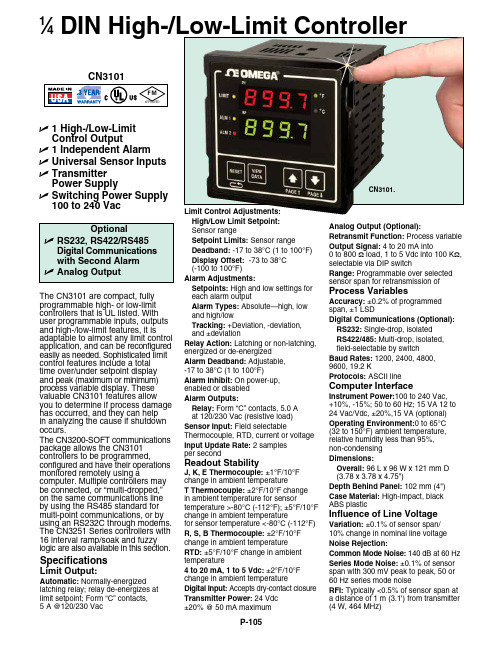
U 1High-/L ow-L imitControl Output U 1 Independent AlarmU U niversal Sensor InputsU T ransmitterPower Supply U S witching Power Supply100 to 240 Vac 1⁄4DIN High-/Low-Limit Controller The CN3101 are compact, fully programmable high- or low-limit controllers that is UL listed. With user programmable inputs, outputs and high-/low-limit features, it is adaptable to almost any limit control application, and can be reconfigured easily as needed. Sophisticated limit control features include a total time over/under setpoint display and peak (maximum or minimum) process variable display. These valuable CN3101 features allow you to determine if process damage has occurred, and they can help in analyzing the cause if shutdown occurs.The CN3200-SOFT communications package allows the CN3101 controllers to be programmed, configured and have their operations monitored remotely using a computer. Multiple controllers may be connected, or “multi-dropped,” on the same communications line by using the RS485 standard for multi-point communications, or by using an RS232C through modems. The CN3251 Series controllers with 16 interval ramp/soak and fuzzy logic are also available in this section.SpecificationsLimit Output:Automatic: Normally-energizedlatching relay; relay de-energizes at limit setpoint; Form “C” contacts, 5 A @120/230 Vac Limit Control Adjustments: High/Low Limit Setpoint: Sensor range Setpoint Limits: Sensor range Deadband: -17 to 38°C (1 to 100°F) Display Offset: -73 to 38°C (-100 to 100°F)Alarm Adjustments: Setpoints: High and low settings for each alarm output Alarm Types: Absolute—high, low and high/low Tracking: +Deviation, -deviation, and ±deviation Relay Action: Latching or non-latching, energized or de-energized Alarm Deadband: Adjustable, -17 to 38°C (1 to 100°F)Alarm Inhibit: On power-up, enabled or disabled Alarm Outputs: Relay: Form “C” contacts, 5.0 A at 120/230 Vac (resistive load)Sensor Input: Field selectable Thermocouple, RTD, current or voltage Input Update Rate: 2 samples per second Readout Stability J, K, E Thermocouple: ±1°F/10°F change in ambient temperature T Thermocouple: ±2°F/10°F change in ambient temperature for sensor temperature >-80°C (-112°F); ±5°F/10°F change in ambient temperature for sensor temperature <-80°C (-112°F)R, S, B Thermocouple: ±2°F/10°F change in ambient temperature RTD: ±5°F/10°F change in ambient temperature 4 to 20 mA, 1 to 5 Vdc: ±2°F/10°F change in ambient temperature Digital Input: Accepts dry-contact closure Transmitter Power: 24 Vdc ±20% @ 50 mA maximum Analog Output (Optional):Retransmit Function: Process variable Output Signal: 4 to 20 mA into 0 to 800 Ω load, 1 to 5 Vdc into 100 K Ω, selectable via DIP switch Range: Programmable over selected sensor span for retransmission of Process Variables Accuracy: ±0.2% of programmed span, ±1 LSD Digital Communications (Optional): RS232: Single-drop, isolated RS422/485: Multi-drop, isolated, field-selectable by switch Baud Rates: 1200, 2400, 4800, 9600, 19.2 K Protocols: ASCII line Computer Interface Instrument Power:100 to 240 Vac, +10%, -15%; 50 to 60 Hz; 15 VA 12 to 24 Vac/Vdc, ±20%,15 VA (optional)Operating Environment:0 to 65°C (32 to 150°F) ambient temperature, relative humidity less than 95%, non-condensing Dimensions: Overall: 96 L x 96 W x 121 mm D (3.78 x 3.78 x 4.75")Depth Behind Panel: 102 mm (4")Case Material: High-impact, black ABS plastic Influence of Line Voltage Variation: ±0.1% of sensor span/ 10% change in nominal line voltage Noise Rejection:Common Mode Noise: 140 dB at 60 Hz Series Mode Noise: ±0.1% of sensor span with 300 mV peak to peak, 50 or 60 Hz series mode noise RFI: Typically <0.5% of sensor span ata distance of 1 m (3.1') from transmitter (4 W, 464 MHz)CN3101.Ordering Examples: CN3101, single output limit controller, 1⁄4 DIN bezel, programmable input, one alarm.OCW-2, OMEGACARE SM extends standard 3-year warranty to a total of 5 years.CN3101-PV-S4, single output limit controller, 1⁄4 DIN bezel, programmable input, 2 alarms, recorder output, and RS485 communications.OCW-2, OMEGACARE SM extends standard 3-year warranty to a total of 5 year.Note: In order to add communications to a CN3101, the housing must be replaced with the 3250X-CASE-COMM so that either the 3250X-S2 or 3250X-S4 communications board can be installed.KTSS-316G-12, molded transition joint thermocouple probe.OMEGACARE SM extended warranty program is available for models shown on this page. Ask your sales representative for full details when placing an order. OMEGACARE SM covers parts, labor and equivalent loaners.。
双佰智能会议指挥系统使用手册
智能会议指挥系统使用手册(奉贤)Version:6.00Date:2010-7-6上海双佰智能科技有限公司目录第1章系统概述 (3)1.1 手册概述 (3)1.2 系统组成 (3)1.3 软件环境 (4)第2章使用说明 (4)2.1 智能化控制系统说明 (4)第1章系统概述1.1 手册概述本手册为操作手册,帮助使用人员更便捷的使用各设备。
1.2 系统组成系统由四大部分组成:指挥中心智能化控制系统、视频监控平台系统、信息发布系统、局长室系统;1.3 软件环境a)信息发布系统:a)操作系统:Windows XP SP3b)发布软件:慧峰数字媒体信息发布系统WiseDisplay b)视频监控平台:a)操作系统:Windows XP SP3/LINUXb)平台软件:博康PEc)智能会议平台:a)操作系统:Windows XP SP3/WINDOWS 2003b)平台软件:ShuangBai HD-PRO第2章使用说明2.1 智能化控制系统说明2.1.1控制系统展示图:中央控制系统图:对照图说明:其中视频跟踪主机、会议主机、串口扩展器、中央控制主机、USB切换主机、视频分割器、音视频矩阵默认为通电开机,可根据需要合理手动控制。
视频跟踪主机:提供摄像机图像的输入、输出、以及通道切换。
会议主机:发言单元、摄像跟踪系统、电话会议系统所必须。
程序设定位FIFO模式,即达到开机数量后,最先开启的发言单元将被后来的发言单元关闭。
串口扩展器:用于串口控制。
主要控制发布系统的三台电视机、投影机、会议室左右电视机的开关机。
中央控制主机:整个智能指挥系统的中央控制系统,控制的主要途径为ST-7600C彩色无线触摸屏以及其中编写的控制程序。
USB切换矩阵:提供USB设备的输入和输出切换,主要的用途是减少设备,便于操作,简洁美观。
视频分割器:提供4画面切割输出。
音视频矩阵:对音视频的输入和输出对应进行控制。
PC、DVD按需求手动开关机,电视盒为、DVD为红外控制,可通过触控屏进行操作。
- 1、下载文档前请自行甄别文档内容的完整性,平台不提供额外的编辑、内容补充、找答案等附加服务。
- 2、"仅部分预览"的文档,不可在线预览部分如存在完整性等问题,可反馈申请退款(可完整预览的文档不适用该条件!)。
- 3、如文档侵犯您的权益,请联系客服反馈,我们会尽快为您处理(人工客服工作时间:9:00-18:30)。
音频事业部
CREATOR 会议系统产品介绍
二. 会议系统发言单元
CREATOR 会 议 系 统 ——产 品 培 训 ——产
广州市天誉科技有限公司
音频事业部
CREATOR 会议系统产品介绍
CR-M3102/4 发言单元实物图 /
CR-M3102 主席单元正视图
CR-M3104 代表单元正视图
CREATOR 会 议 系 统 ——产 品 培 训 ——产
CR-M3101 前面板
CR-M3101 后面板
CREATOR 会 议 系 统 ——产 品 培 训 ——产
广州市天誉科技有限公司
音频事业部
CREATOR 会议系统产品介绍
CR-M3101主机功能简述 主机功能简述
1. 2. 3. 4. 5. 6. 7. 8. 9. 10. 11. 12. 13. 系统主机最多可连接128台发言单元,通过扩展口接入扩展主机(多个扩展主机之间手拉手串联连接),最多可 接入4096台发言单元,且相互无干扰 最多可连接5台翻译单元,实现5+1语种同声传译功能 "手拉手"电缆串接模式,便于安装和维护 具有音频输入接口,可输入外部音频信号(如背景音乐) 具有多组音频通道输出,可连接PA功放对发言者的讲话进行放大输出,也可连接卡座进行录音 发言人数限制功能:限定当前最多发言单元,当发言单元达到定值时,要打开其它发言单元,必须先关闭已打开 的发言单元,发言单元数量1、2、4、6可调,主席单元不受限制 先进先出功能:如果当前发言人数已经达到最大值,后打开的发言单元会自动取代之前最早打开的发言单元,发 言单元数量1、2、4、6可调,主席单元不受限制 内置均衡器,对系统输出的音频信号进行高、低音调节,以适应不同的听觉要求 内置移频器,有效抑制啸叫 配合中央控制系统可实现由中央控制系统对会议系统进行统一管理,全面代替管理软件,如各种会议模式的选择 和配置、发言人数的设定等,真正意义上的“会议+中控无缝结合” 配合摄像跟踪系统可实现视像自动跟踪功能 投票表决功能及数据管理功能 配合电话耦合器可以进行远程电话会议
CREATOR 会 议 系 统
会议室的构成 会议系统的组成、功能 会议系统的组成、 CREATOR 会议系统产品介绍ห้องสมุดไป่ตู้ CREATOR 会议系统方案配置
广州市天誉科技有限公司 音频事业部
CREATOR 会 议 系 统 ——产 品 培 训 ——产
广州市天誉科技有限公司
音频事业部
会议室的构成
会 议 室 音 频 会 议 系 统 扩 声 系 统 视 频 节 目 源
音 频 输 出 / 入
会议系统主机
音 频 输 入 音 频 输 出 音 频 输 出 控 制 接 口 控 制 接 口
发 言 单 元 接 口
电话会议 背景音乐 扩声系统 录音系统
摄像跟踪/ 摄像跟踪 控制系统
主席单元
代表单元
代表单元
管理软件
CREATOR 会 议 系 统 ——产 品 培 训 ——产
广州市天誉科技有限公司
CR-ME2000 后面板
CREATOR 会 议 系 统 ——产 品 培 训 ——产
广州市天誉科技有限公司
音频事业部
CREATOR 会议系统产品介绍
CR-M2201主机实物图 主机实物图
CR-M2201 前面板
CR-M2201 后面板
CREATOR 会 议 系 统 ——产 品 培 训 ——产
广州市天誉科技有限公司
CREATOR 会 议 系 统 ——产 品 培 训 ——产
广州市天誉科技有限公司
音频事业部
CREATOR 会议系统产品介绍
CR-M2201主机后面板解释图 主机后面板解释图
扩声系统 录音系统 电话会议 背景音乐 电话会议 门禁/自检 门禁/ 管理软件 控制系统 摄像跟踪
话筒
扩展 主机
发言单元 /表决单元
均 衡 高 音 调 节
系 统 音 量 调 节
CREATOR 会 议 系 统 ——产 品 培 训 ——产
广州市天誉科技有限公司
音频事业部
CREATOR 会议系统产品介绍
CR-ME2000 扩展主机功能简述
配合CR-M3101系统主机扩展连接发言单元 一台扩展主机最多可连接128台会议单元
CR-ME2000 前面板
CREATOR 会 议 系 统 ——产 品 培 训 ——产
广州市天誉科技有限公司
音频事业部
CREATOR 会议系统产品介绍
一. 会议系统主控单元
CREATOR 会 议 系 统 ——产 品 培 训 ——产
广州市天誉科技有限公司
音频事业部
CREATOR 会议系统产品介绍
CR-M3101主机实物图 主机实物图
摄像跟踪/ 摄像跟踪 控制系统
主席单元 表决单元
红外接收单元
代表单元 表决单元
红外接收单元 红外接收单元
代表单元 表决单元
红外接收单元 红外接收单元 红外接收单元 红外接收单元
管理软件 红外发射主机
红外接收单元
红外辐射面板
红外辐射面板
CREATOR 会 议 系 统 ——产 品 培 训 ——产
广州市天誉科技有限公司
摄像跟踪/ 摄像跟踪 控制系统
主席单元
代表单元
代表单元
管理软件
红外接收单元 红外接收单元 红外接收单元 红外接收单元 红外接收单元 红外接收单元 红外接收单元
红外发射主机
红外接收单元
红外辐射面板
红外辐射面板
CREATOR 会 议 系 统 ——产 品 培 训 ——产
广州市天誉科技有限公司
音频事业部
会议系统的组成、功能 会议系统的组成、
讨论发言、同声传译、投票表决会议系统概图 讨论发言、同声传译、 讨论发言
音 频 输 出 / 入 音 频 输 入 音 频 输 出 音 频 输 出 语 种 通 道 输 出
会议系统主机
控 制 接 口 控 制 接 口
表 决 单 元 接 口
发 言 单 元 接 口
翻 译 单 元 接 口
翻译单元
翻译单元
电话会议 背景音乐 扩声系统 录音系统
CREATOR 会 议 系 统 ——产 品 培 训 ——产
广州市天誉科技有限公司
音频事业部
CREATOR 会议系统产品介绍
CR-M3101主机后面板解释图 主机后面板解释图
背景音乐 电话会议 红外语音 分配系统 扩展主机 控制系统 摄像跟踪 管理软件
扩声系统 录音系统 电话会议
翻译单元 ≤5
发言单元 /表决单元 ≤128
CREATOR 会 议 系 统 ——产 品 培 训 ——产
广州市天誉科技有限公司
音频事业部
CREATOR 会议系统产品介绍
系统设计的指导思想和原则
可维护性: 可维护性:系统的可维护性是非常重要的,好的系统结构和系统设计会降低维护的费用和升级费用,延长使用寿命, 提高维护效率,保障会议的正常进行。 1. 2. 3. 系统在设计时,结构尽量简单、合理、灵活。由于采用手拉手的连接方式,不仅减少施工难度,降低故障率, 而且便于系统维护,很容易诊断和定位故障,及时修复。 系统维护无需太多的专业技能,普通的技术人员经过短期的培训便可以实施。 每套系统都经过严格的测试及试验,符合国际性的ISO9001质量体系标准。
可扩展性: 可扩展性:随着科技的发展,会议系统的要求也越来越高,系统的可扩展性也越来越重要。 1. 2. 由于系统结构简单、合理,扩展性极强,增加更多的发言单元便可以满足人数的增加。 系统功能的模块化,配置连接其他的设备便可以满足功能的增加,如增加投票表决系统就可同时进行投票表 决会议;增加摄像跟踪系统就可同时进行摄像跟踪实现视听同步,增加电话会议系统,连接宽带或ISDN就可 以与多方进行面对面的交流等等。
投 影/显 示 系 统 远 程 视 频 会 议 多 媒 体 控 制 系 统 信 号 处 理 系 统 智 能 集 中 控 制 系 统
CREATOR 会 议 系 统 ——产 品 培 训 ——产
广州市天誉科技有限公司
音频事业部
会议室的构成
CREATOR 会 议 系 统 ——产 品 培 训 ——产
广州市天誉科技有限公司
音频事业部
CREATOR 会议系统产品介绍
CR-M2201主机功能简述 主机功能简述
1. 2. 3. 4. 5. 6. 7. 8. 9. 10. 系统主机最多可连接64台会议单元,通过扩展口级联,会议单元可无限扩展连接 "手拉手"电缆串接模式,便于安装和维护 具有音频输入接口及手持麦克风输入接口,并具电平调节 内置移频器,有效抑制啸叫 前面板液晶显示菜单操作信息,使得整个系统功能设置显得非常直观 发言人数限制功能:通过主机前面板操作菜单可自由设置 先进先出功能:除主席单元外,通过前面板菜单操作设置同时发言单元数量,后打开的会自动将之前已经打开的 发言单元关闭 配合中央控制系统可实现由中央控制系统对会议系统进行统一管理,全面代替管理软件,如各种会议模式的选择 和配置、发言人数的设定等,真正意义上的“会议+中控无缝结合” 配合电话耦合器可以进行远程电话会议 配合摄像跟踪系统视频切换主机可实现摄像自动跟踪功能
音频事业部
会议系统的组成、功能 会议系统的组成、
会议讨论系统 同声传译系统 投票表决系统 电话会议系统 摄像跟踪功能 软件管理功能
CREATOR 会 议 系 统 ——产 品 培 训 ——产
广州市天誉科技有限公司
音频事业部
会议系统的组成、功能 会议系统的组成、
讨论发言会议系统概图 讨论发言会议系统概图
单元 编号
翻译单元
≤64
≤11
CREATOR 会 议 系 统 ——产 品 培 训 ——产
广州市天誉科技有限公司