1通道或2通道 圆形图表记录仪CT5100系列
Nailor CTE-5100系列温控器操作手册说明书
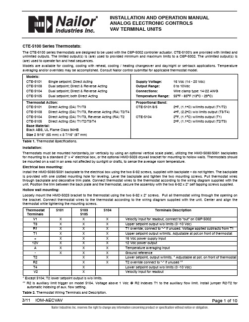
INSTALLATION AND OPERATION MANUALANALOG ELECTRONIC CONTROLSVAV TERMINAL UNITSCTE-5100 Series Thermostats:The CTE-5100 series thermostats are designed to be used with the CSP-5002 controller actuator. CTE-5100’s are provided with limited and unlimited outputs. The limited output(s) is (are) used to provided minimum and maximum limits to a CSP-5002. The unlimited output(s) is (are) used to operate fan and heat sequences.Models are available for cooling, cooling with reheat, cooling / heating changeover and day/night or set-back applications. Temperature averaging and/or overrides may be accomplished. Consult Nailor control submittal for applicable thermostat model.Models:CTE-5101Single setpoint; Direct Acting Supply Voltage:16 Vdc (14 - 20 Vdc)CTE-5103Dual setpoint; Direct & Reverse Acting Output Range:0 to 10VdcCTE-5104Dual setpoint; Direct & Reverse Acting Connections:Wire clamp type: 14-22 AWGCTE-5105Dual setpoint; both Direct Acting Temperature Range:55O F - 85O F (13O C - 29O C)Thermostat Action:Proportional Band:CTE-5101Direct Acting (DA) T1/T3CTE-5101/3/52O F, (1.1O C) w/limits output (T1/T2)CTE-5103Direct Acting (DA) T1/T3, Reverse Acting (RA) T2/T44O F, (2.2O C) w/o limits output (T3/T4) CTE-5104Direct Acting (DA) T1/T3, Reverse Acting (RA) T2CTE-51042O F, (1.1O C) w/limits output (T1)CTE-5105Direct Acting (DA) T1/T2/T3/T42O F, (1.1O C) w/limits output (T2/T3)Base Material:Black ABS, UL Flame Class 94HBSize2 9/16" (65 mm) x 3 7/16" (87 mm)Table 1.Thermostat Specifications.Installation:Thermostats must be mounted horizontally,(or vertically by using an optional vertical scale plate), utilizing the HMO-5030/5031 backplates for mounting to a standard 2" x 4" electrical box, or the optional HMO-5023 drywall bracket for mounting to hollow walls. Thermostats should be mounted on a wall in an area not affected by sunlight or drafts, to sense the average room temperature.Electrical box mounting:Install the HMO-5030/5031 backplate to the electrical box using the two 6-32 screws, supplied with backplate – do not tighten. The backplate is provided with one slotted mounting hole for leveling. Level the backplate and tighten the two mounting screws. Pull thermostat wires through backplate and decorative trim plate. Connect thermostat wires to the thermostat according to the wiring diagram supplied with the unit. Position the trim between the back plate and the thermostat, secure the assembly with the two 6-32 x 2" self tapping screws supplied. Hollow wall mounting:Loosely mount the HMO-5023 bracket to the thermostat using the two 6-32 x 2" screws. Pull all thermostat wiring through the opening on the bracket. Connect thermostat wires to the thermostat according to the wiring diagram supplied with the unit. Center and align the thermostat while tightening the mounting screws.Thermostat510151035104Terminals DescriptionTerminals5105V1X X X Velocity input for readout, connect to “out” on CSP-5002T3X X X Upper setpoint output w/o limits (0 -10 Vdc)R1X X X T1 override, connect to "-" if unused. Voltage applied subtracts from T1 T1X X X Upper setpoint output w/limits. Adjustable at pot.on front of thermostat +X X X16 Vdc power supply input12V X X X12 Vdc power outputA X X X Temperature averaging input-X X X Ground referenceT2X X Lower setpoint, output w/limits. * Adjustable at pot. on front of thermostat R2X X T2 override connect to "-" if unused **T4X Lower setpoint output w/o limits (0 -10 Vdc)V2X Velocity input for readout* Except 5104; T2 lower setpoint output is w/o limits.** R2 is auxiliary limit trigger on model 5104. Voltage above 1 Vdc @ R2 indexes T1 to the auxiliary flow limit. Install jumper R2-T2 for automatic indexing of aux. flow setting.Table 2.Thermostat Wiring Terminals and Description.Figure 1. Thermostat Detail Maintenance:No routine maintenance is required. Each component’s design and material selection assures dependable long-term reliability and performance. Careful installation will also enhance long term reliability and performance.CSP-5002 DAMPER CONTROLLER/ACTUATORAll Nailor standard right hand (and optional left hand) terminal units have a 1/2" (13), diameter drive shaft and a clockwise to close damper rotation (Dual Duct Left Hand Deck CCW to close). Full damper shaft rotation is 45 or 90 degrees depending on model. The CSP-5002should be mounted on the damper drive shaft so the actuator will stall at either end of the stroke to ensure tight shut-offs and full rotation.Ensure the two jumpers are set for the correct damper rotation.The CSP-5002 has a tri-color LED that indicates the current action of the damper: RED – Closing, GREEN – Opening, WHITE – Satisfied.The CSP-5002 provides pressure independent VAV control for terminal unit primary valves. Primary air volume is monitored by the use of a multi-point flow sensor located in the inlet duct. Differential pressure is measured by an onboard platinum transducer. The changes in the inlet static pressure will vary the position of the inlet damper. Flow limit adjustments are made using a digital DC voltmeter at the thermostat.The CSP-5002 is factory calibrated with VNOM adjustment centered for the enclosed voltage - airflow charts. Do not adjust. Dampers are always shipped in the full open position.(WHERE APPLICABLE)ACESS DOOR GEAR DISENGAGEMENT BUTTONP PORTS 3/16" (5) DIA. (2)Figure 2. CSP-5002 Controller / ActuatorPOWER REQUIREMENTS:Controller / actuator / thermostat is 7VA plus any output loads for fan relays, heating contactors and control valves (assume 10 VA each).Always switch control voltage off prior to disconnecting any wires from the controller.ANALOG CONTROL CALIBRATION CHARTS VOLTAGE VS. AIRFLOWWhen field adjustment or field calibration of the CTE-5100 series thermostats is necessary, desired limit control can be calculated using the tables in Figure 3 and the following formulas, or the charts presented in Figures 4 through 8.Formulas:CFM = K (VDC - Offset)VDC = (CFM/K) + Offset Follow the individual calibration procedure for the thermostat model(s) as required.Inlet sizeK factorOffset14 x 10417- 0.1424 x 161250- 0.07Inlet sizeK factorOffset4 in. Round 33+ 0.445 in. Round 55+ 0.026 in. Round 75+ 0.087 in. Round 115- 0.198 in. Round 143+ 0.329 in. Round 175+ 0.1010 in. Round 233+ 0.0912 in. Round 357- 0.0414 in. Round 500- 0.0716 in. Round625- 0.25Inlet sizeK factorOffset12 in. Oval 333- 0.2214 in. Oval 417- 0.4716 in. Oval 588+ 0.0518 in. Oval759- 0.27Figure 3.Diamond Flow Sensor K Factors.2.03.04.05.06.07.01.0V O L T S , D C100200300400600500AIRFLOW,CFMFigure 4.Inlet Sizes 4, 5, 6 Round2.03.04.05.06.07.08.01.0V O L T S , D C100200300400600500800700900110010001200140013001500AIRFLOW,CFMFigure 5.Inlet Sizes 7, 8, 9, 10 Round2.03.04.05.06.07.01.0V O L T S , D C5001500100025002000300040003500AIRFLOW,CFMFigure 6.Inlet Sizes 12, 14, 16 Round. 14 x 10 Rectangular02.03.04.05.06.07.01.0V O L T S , D C5001500100025002000300040003500AIRFLOW,CFMFigure 7.Inlet Sizes 12, 14, 16 Oval (Single Duct Only)02.03.04.05.06.07.01.0V O L T S , D C500150010002500200030004000350045005500500060006500700080007500AIRFLOW,CFMFigure 8.Inlet Size 18 Oval. 24 x 16 RectangularCALIBRATION PROCEDURE FOR AIR VOLUME ADJUSTMENTS MADE AT THERMOSTATThermostats are factory calibrated when minimum and maximum airflow limits are provided. Field calibrations are as follows:Minimum and maximum setpoints (air volume limits), are set at the thermostat. Check the CSP-5002 controller to ensure that the minimum and maximum potentiometers are dialed completely out (min. CCW, max. CW), so that the thermostat signal is not restricted.A – Required Tools:1. Small flat blade screwdriver 1/8" / 3 mm 3. Hex Wrench 1/16" / 2mm for the cover screws2. Digital voltmeter w/DC range to hundredths 4. A test lead (HSO-5001) is recommended for meter readingsB – Remove Thermostat Cover:Thermostat cover is removed by turning the two set screws CW, (which are located on the short sides of the thermostat). Remove cover and setpoint slider stops if installed.Figure 9.Thermostat scaleplate detail.CTE – 5101 SINGLE SETPOINT THERMOSTAT(DA T1 with limits, T3 without limits)1. Ambient temperature at the thermostat must be between 55O F – 85O F (13O C – 29O C).2.Adjust the setpoint slider all the way to the right for minimum cooling. Connect voltmeter to the cooling (right side) voltmeter taps. The center and right tap provide the VDC readings (min/max airflow). The center and left tap provide the actual air volume (live velocity)reading when thermostat V1, is connected to the controller OUT terminal.3.Read the VDC across the taps. Adjust the MIN INCR potentiometer to the VDC equal to the desired air volume as shown on the chart.NOTE: The minimum setpoint must be set first. Adjustment of the minimum potentiometer directly affects the maximum setpoint.4.Adjust the setpoint slider all the way to the left for maximum cooling.5.Read the VDC across the taps. Adjust the MAX INCR potentiometer to the VDC equal to the desired air volume as shown on the chart.NOTE: The maximum setpoint must be set last. Adjustment of the minimum potentiometer directly affects the maximum setpoint.6.Return the setpoint slider to the desired setpoint. Install the optional setpoint stops if required and replace thermostat cover.CTE - 5103 DUAL SETPOINT THERMOSTAT (Heat / Cool Changeover)(DA T1/T3. RA T2/T4. T1, T2 with limits, T3, T4 without limits)Cooling side of thermostat1.Follow steps 1 through 5 for the CTE-5101 thermostat. Note: Be sure to adjust the cooling setpoint slider all the way to the left for maximum cooling. (The heating setpoint sider will have to be adjustable all the way to the left also).Heating side of thermostat1.Ambient temperature at the thermostat must be between 55O F - 85O F (13O C - 29O C).2.Adjust the heating setpoint slider all the way to the left for minimum heating. Connect voltmeter to the heating (left side) voltmeter taps.The center and right tap provides the VDC readings (min/max airflow).3.Read the VDC across the taps. Adjust the MIN INCR potentiometer to the VDC equal to the desired air volume as shown on the chart.NOTE: The minimum setpoint must be set first. Adjustment of the minimum potentiometer directly affects the maximum setpoint.4.Adjust the heating slider all the way to the right for maximum heating.5.Read the VDC across the taps. Adjust the MAX INCR potentiometer to the VDC equal to the desired air volume as shown on the provided chart.NOTE: The minimum setpoint must be set first. Adjustment of the minimum potentiometer directly affects the maximum setpoint.6.Return both setpoint sliders to the desired setpoints. Install the optional setpoint stops if required and replace thermostat cover.SCALE PLATE (°F OR °C)METER TAPCTE – 5104 DUAL SETPOINT THERMOSTAT(DA T1/T3. RA T2. T1 with limits, T2, T3 without limits)Cooling side of the thermostat1.Follow steps 1 through 5 for the CTE-5101 single setpoint thermostat. Note: Be sure to adjust the cooling setpoint slider all the way to the left for maximum cooling. (the heating setpoint slider will have to be adjustable all the way to the left also).Adjustment of the Auxiliary Setpoint - Higher reheat minimum (if required).2.Read the VDC across the meter taps on the heating (left) side of the thermostat. With the left hand slider in the full heat position,completely to the right, adust the MAX/AUX INCR potentiometer to the VDC equal to the desired air volume as shown on the chart. If a higher Aux Min is not required, dial fully CCW.3.Return both setpoint sliders to the desired setpoints. Install the optional setpoint stops if required and replace thermostat cover.CTE – 5105 DAY / NIGHT THERMOSTAT (Night Temperature Set Back)(DA T1/T2/T3/T4. T1/T2 with limits, T3/T4 without limits)Day side of thermostat1.Follow steps 1 through 5 for the CTE-5101 thermostat.Note: Be sure to adjust the day setpoint slider all the way to the left for maximum cooling. The night setpoint slider will have to be adjusted all the way to the left also.2.Return both setpoint sliders to the desired setpoints. Install the optional setpoint stops if required and replace thermostat cover.Night side of thermostat1.Follow steps 1 through 5 for the CTE-501 thermostat.Note: Be sure to adjust the night setpoint slider all the way to the right for minimum cooling. The day setpoint slider will have to be adjusted all the way to the right also.2.Return both setpoint sliders to their desired setpoints. Install the optional setpoint stops if required and replace thermostat cover.Figure 10.Thermostat action schematics.-2F Dir. Act. S.P . +2F -2F Dir. Act. S.P .+2F(Night) (Day)-2F Rev. Act. S.P .+2F -2F Dir. Act. S.P .+2F(Heating) (Cooling)CTE-5105 Thermostat-2F Rev. Act S.P. Dir. Act. S.P. +2F(Heating) (Cooling)CTE-5104 Thermostat V D C O u t p u t-2F S.P . +2FCTE-5101 Thermostat V D C O u t p u tCTE-5103 ThermostatV D C O u t p u tV D C O u t p u tGENERAL INFORMATION FOR ALL TERMINAL UNITSCheckout ProcedureThe CSP-5002 actuator will take up to 2.5 minutes for a 45 degree stroke damper and up to 5.0 minutes for a 90 degree stroke damper to cycle from its minimum to its maximum setting and vice versa. It is important therefore when verifying minimum and maximum flow limits, by moving the slider(s) right or left as previously described, to wait sufficient time to ensure the actuator has moved to its correct position and that the live velocity read-out (if used) has settled.Live Supply Volume ReadoutA voltage output corresponding to actual primary air volume may be monitored at the room thermostat to assist in balancing and troubleshooting. The output signal is the same as the airflow volume vs. DC voltage calibration curve. The test lead (HSO-5001) is connected to the innermost meter taps on the thermostat scaleplate (see Figure 9).Supply Air Temperature SensingA duct mounted temperature sensor (thermistor) is used to measure primary air temperature in control sequences involving automatic changeover (ACO) or morning warm-up (MWU). The probe is attached to the inlet collar and wired to the low voltage controls enclosure. To ensure proper operation for auto changeover, a minimum flow setting should be used for both heating and cooling modes. This allows airflow to constantly pass over the duct temperature sensor.Proportional Reheat ControlHot water valves and SCR controllers with a 0 -10 Vdc control signal (10mA max,) are wired (+) to terminal ‘T2’ on the thermostat and (-) to the grounded side of the low voltage control circuit. T2 is an output with limits and it must therefore be ensured that the thermostat limits are dialed out (max. pot. fully CW and min. pot fully CCW) for unrestricted operation.FAN POWERED TERMINAL UNITSNight Shut DownUnits ordered with optional Night Shut Down (NSD) sequences employ an airflow switch to sense when primary air has been shut down. When the airflow switch opens the fan and optional heat are shut down. Upon the primary air starting, the airflow switch will close and return the unit to normal operation.Night Temperature SetbackUnits ordered with optional Night Temperature Setback (NTSB) sequences employ an airflow switch to sense when the primary air (central air handler) has been shut down. When the airflow switch opens, a lower night time temperature setpoint is initiated. The unit fan and optional supplementary heat will cycle intermittently to maintain night setpoint temperature. Upon start up of the central air handler, the unit will return to daytime operation. Amount of setback is either fixed or adjustable dependent on control sequence. Refer to control submittal. Night CycleOn series units with optional night cycle sequences, an airflow switch de-energizes unit fan upon loss of primary (central system) air. Upon a call for heat, the thermostat will override the airflow switch and cycle the unit fan followed by any supplementary heat intermittently to maintain day setpoint temperature.On parallel units, basic control sequences cycle the fan and supplementary heat intermittently as standard in response to thermostat demand. This will therefore still occur at night when the central air has been shutdown.Checkout Procedure (Day / Occupied Mode)Series Fan Powered Terminal Units: The fan should be energized regardless of slider(s) position. Dependent on control sequence ordered, thermostat may have one or two sliders. Consult control sequence submittal / wiring diagram and thermostat calibration procedure.Parallel Fan Powered Terminal Units: Fan will only cycle upon a call for heat. Move single slider (or both if a separate heating or night slider is present) full right to energize fan. Dependent on control sequence ordered, thermostat may have one or two sliders. Consult control sequence submittal / wiring diagram and thermostat calibration procedure.Checkout Procedure (Night / Unoccupied Mode)Move thermostat slider(s) full right to energize fan and supplementary heat.TROUBLESHOOTING PROCEDURENote: Turn off power before making any wiring changes to the unit.1. Verify 24 Vac at CSP-5002 controller / actuator terminals "~" (phase) and "-"(ground). Tolerance +20 / -15% (20.4-28.8 Vac). When using a common transformer for more than one CSP-5002, polarity should be observed.2. Check correct field wiring from thermostat to terminal block in unit low voltage enclosure. Refer to Nailor control wiring diagram inside controls enclosure. Ensure all wiring connections are tight and secure.3. Check tubing from unit inlet flow sensor to the controller / actuator is correct and no leaks. "Hi" side of sensor to "H" on controller / actuator and "Lo" side of sensor to "L" on controller / actuator.4. Verify 16 Vdc at CSP-5002 terminals "16 VDC" and "-". Tolerance is 15 to 17 Vdc power supply to thermostat. If not correct, disconnect thermostat and recheck. If still incorrect, replace CSP-5002 controller / actuator.5. Check requested minimum and maximum flow settings on terminals "IN" and "-". Refer to Vdc vs. Airflow setting charts at back of this document. If reading is not what is desired, refer to thermostat calibration procedure.6. Check actual airflow (live velocity readout) voltage on terminal "OUT" and "-" (0 – 10 Vdc). Use calibration charts provided.7. Check for damper movement and correct rotation.a) Review "requested flow" and actual flow" above to determine if unit should be satisfied (within 50 fpm +/- 0.20 Vdc) or driving damper open or closed.b) If damper is not moving, verify damper is not stuck at end of travel and has free movement. Use manual release clutch on CSP-5002.Check CW / CCW rotation jumpers for proper operation. Ensure damper actuator connection is correct and damper can travel fully open to fully closed within limits of the actuator stroke. Check actuator coupling to damper shaft setscrews are tight.c) Change "requested flow" to make unit drive opposite direction (verifying correct damper movement). This can be accomplished by moving thermostat setpoint sliders or:i) To manually open damper, remove wire from terminal "IN" and jumper terminal "IN" to 16Vdc". This will tell unit to control at full airflow and the green LED should turn on, driving damper fully open.ii) To manually close damper, remove wire from terminal "IN" and jumper terminal "IN" to "-" terminal. This will tell unit to control at zero airflow and the red LED should be on, driving damper fully closed.Warning:Never jumper terminal "16 Vdc" to "-", as this will cause short and possibly damage the power supply.REE – 5002 Relay Module Fan with 2 Stage ReheatThe REE-5002 is used in all parallel flow terminal units, and specific series flow terminal units with the night cycle or setback options. The relay cycles the fan and activates up to 2 stages of heat in response to a direct acting 0 -10 Vdc thermostat output. The fan start point is adjustable from 3-8 Vdc which equates to -0.8 to +1.2O F,(-0.4 to +0.7O C), around setpoint. The factory setting is 4 Vdc (-0.4F below cooling setpoint / min. primary airflow setting). To field adjust, read the Vdc across terminals "X" and "-". Adjust the potentiometer to Vdc desired setpoint. The two stages of heat are sequenced to energize after the fan is activated when the desired room temperature continues to decrease.CSP-5001CONTROLLER-ACUATORFigure 11.Ree-5002 Relay Module. Fan with 2 stage reheat.THERMOSTAT SIGNAL (T3)(1 VDC SWITCHING DIFFERENTIAL)S TA GE SFAN 1 1 3 8 VOLTS 2DESCRIPTIONVENDOR PART NO.NAILOR PART NO.KMC Controller / Actuator CSP-5002V3004(Kreuter)Controller / Actuator CSP-4606V3005Controller / ActuatorCSP-4616V3006In-line filter for CSP-4XXXHFO-0034V3007KMC (Kreuter) Room Thermostat and accessories:CTE-5100 Series - (0 -10 Vdc):DA clg. (base only)CTE-5101V3030DA clg. / RA htg. (base only)CTE-5103V3031DA clg./RA reheat (base only)CTE-5104V3032DA / DA (Day / Night) (base only)CTE-5105V3033Accessories for CTE-5100 Series:Thermostat Cover - light almondHPO-1511V1060- WhiteHPO-1512V1061Backplate mounting kit(for mounting to a 2 x 4 handy box) - light alomdHMO-5024V1062- WhiteHMO-5026V1063Mounting Strap kit (for mounting on holllow wall)HMO-5023V1064Horizontal Scale Plate - O FHPO-0060-10V1069- O CHPO-0060-11V1070Miscellaneous:KMC Electric reheat relay module, 3 stage REE-5001V3050KMC Wet heat time prop. relay module DA/NC valve REE-5106V3053RA/NO valve REE-5123V3054KMC Fan/elec. heat relay module, 2 stage REE-5002V3055KMC Fan/wet heat time prop. relay moduleDA/NC valve REE-5017V3056RA/NO valveREE-5024V3057KMC Constant volume relay module REE-1004V3058KMC Heat / Cool changeover moduleREE-1005V3059KMCDuct temp. changeover sensor (for use with REE-1005)STE-1002V3060Airflow Switch FS-BO-182V3061DPDT Relay 24V.9100-233Q323V3062Transformers (foot mount):120to 24 V. 40 VA -VH1-669120to 24 V. 50 VA -VH1-692208/240to 24 V. 40 VA -VH1-670208/240to 24 V. 50 VA -VH1-685277to 24 V. 40 VA -VH1-675277to 24 V. 50 VA -VH1-674277to 24 V. 75 VA -VH1-677480to 24 V. 50 VA -VH1-686208/240/480to 24 V. 40 VA -VH1-671120/208/240/480to 24 V. 75 VA -VH1-68924to 24 V. 40 VA-VH1-673COMPONENTS, ACCESSORIES, REPLACEMENT PARTSCalgary, Canada Tel: 403-279-8619Fax: 403-279-5035Houston, TexasTel: 281-590-1172Fax: 281-590-3086Las Vegas, Nevada Tel: 702-648-5400Fax: 702-638-0400Toronto, Canada Tel: 416-744-3300Fax: 416-744-3360。
AMETEK 手册-5100-5100HD-Rev-E
| II
目录Leabharlann 办公室....................................................................................................................................... II 安全提示..................................................................................................................................VI 用电安全..................................................................................................................................VI 接地..........................................................................................................................................VI 样品气体..................................................................................................................................VI 警告标签....................................................................................
NTRON5100氧气分析仪中文说明书
MODEL 5100 氧气分析仪—百分比量程操作手册REVISION 03001Ntron目录安全提示 (3)规格表 (4)产品保证书 (4)第一部分工作原理1.1 概括 (5)1.2 特征 (6)1.3 系统组成 (7)1.3.1 主板 (7)1.3.2 继电器板 (7)1.3.3 电源 (7)1.3.4 显示板 (7)1.3.5 控制面板 (7)1.3.6 传感器 (7)1.3.7 单元组和单元组帽 (8)1.3.8 底板 (8)第二部分 5100分析仪操作2.1 安装 (10)2.1.1 分析仪的安装位置 (11)2.1.2 分析仪的安装 (11)2.1.2.1 管路安装 (12)2.1.2.2 电气连接 (12)2.2 开始2.2.1 通电前检查 (14)2.2.2 通电 (14)2.2.3 校准 (14)2.2.4 报警设置 (15)2.2.5 返回运行形式 (15)第三部分操作形式3.1 运行 (16)3.2 校验 (17)3.3 设置或查看报警 (19)3.4 FL-自诊断故障 (19)3.5 报警激活形式 (19)第四部分模拟范围 (20)第五部分报警输出 (21)第六部分通讯接口 (22)第七部分维护 (24)第八部分常见问题 (25)安全提示:安装或操作之前请详细阅读操作手册。
(在没有完全明白型号5100的特征和功能之前而进行操作,可能会造成不安全。
) 气体加压时,使用保护眼罩和遵守安全的程序。
确保进入的气体气压为1—3PSIG。
测量气体要在相同压力和流动速度下校准。
接近传感器之前,必须待传感器冷却后。
使用期期满,氧气传感器可适当处理。
确保在使用之前已经校准仪器。
测试环境和测试气体不结露。
不要置于高温环境。
不要直接输入不规则的气体、高压气体以防氧气管爆裂。
确保分析仪的操作温度,不要置于高温的表面,不要阻塞通风口。
不要置于易燃物质旁。
表 1 型号 5100 规格传感器内置加热器的微型氧化锆氧传感器测量量程 0-1%/0-10%/0-25%/0-50%/0-100%,O2自动量程或固定量程显示0.75''LED 数字显示显示精度 :1%量程:.xx, 10%量程: x.xx,25%/50%/100% 量程: xx.x系统状态LED指示灯:故障时为黄灯,正常和在线测量为绿灯。
保护传感器测试系统 MTS-5100 说明书

MTS-5100Advanced Test Equipment Corp. 800-404-ATEC (2832)Protective Relay Test SystemAt a Glancefi tsSteady-state testingDynamic testing - step/ramp/state sequence Transient waveform testing GPS time synchronized testingDirect front panel interface for all functions Intuitive operationExceptional productivity for common tasks All-in-one, no options required Very high VA current output channels Realistic fault quantities and waveforms(Even under ordinary manual testing)Onboard memory + USB memory driveTransmission & Distribution: overcurrent, under/overvoltage, directional overcurrent, distance,frequency, line differential, transformer differential (1-phase, 3-phase), bus differential, capacitorprotection, out-of-step, synchrocheck, reclosing, breaker failure, lockout, time-delay, and auxiliary relaysGenerator Protection and Control: differential, loss-of-fi eld, under/overvoltage, overexcitation,stator ground, negative sequence, frequency, unbalance, reverse power, out-of-step, synchronizing, Synchro-check, lockout, time-delay, and auxiliary relaysIndustrial: overcurrent, under/overvoltage, transformer differential, bus differential, capacitor,overload, motor protection, lockout, time-delay, and auxiliary relaysOther: Current, Voltage, Watt, VAR, and Frequency transducers and meteringThe MTS-5100 Protective Relay Test SystemWhat Can It Do For You?The MTS-5100 is the most powerful all-in-one relay test system with a direct front panel interface for all functions, without exception! The ideal system for testing and calibrating protective relays using traditional test techniques or applying realistic power system simulations.Easily test single overcurrent relays to multi-terminal end-to-end schemes with this one box. No add-ons. No hidden costs. The MTS-5100 includes all the power (VA) that you need for old electromechanical relays in each output channel to minimize connection changes, with all of the output current and voltage channels you need for modern microprocessor-based relays. Powerful productivity functions and built-in intelligence make it a simple task to perform realistic power system simulations which increases productivity and effectiveness. You can even save your test results directly from the front panel to simplify your NERC/FERC reporting requirements.All the Necessary Output Channels and Inputs for Protectionand Control Relay Testing6 AC/DC Currents6x30Arms, 3x60Arms,1x180Arms4 AC/DC Voltages4x250Vrms, 1x750Vrms12 Contact / 0-250Vrms Voltage inputs4 Contact outputsTransducer voltage/inputUSB MemoryGPS inputIRIG inputIRIG outputIE C 61850310.4” screen! Larger thanmost tablet computers.fi nedBacklit display visible inthe brightest sunfi ngers! Low activationfi neVGA output for external monitoror projectorC 61850, computer control or5Be Productive the Very FirstDay Novices and veterans alike need help to keep up with the rapid advances in protection technology to contend with the complexities of testing today’s sophisticated relays and systems. In fact, a IEEE Power System Relaying Committee’s Survey on Relay Test Practices found that “most relay test personnel receive fewer than 16 hours of relay training per year.”* That’s why we started from scratch to create atruly “intuitive to use” relay test set, so that you’ll be productive from the very fi rst day. The MTS-5100 provides built-in intelligence to simplify its advanced testing capabilities and controls required for multipleinput and output channels. Here are a few examples:Relay test screens that simplify the testing of common relay types. Each screen is designed to get the jobdone in the fewest number of steps.You’ve tested differential relays before,but can you remember the formulaeand test connections for the differentconfi gurations?The MTS-5100 confi gures itself, drawspictures of the connections, lists theformulae, and calculates the results.Improve your effi ciency even more bysaving settings for often used tests rightin the built-in memory and recallingthem later. Use a USB memory deviceto use your test settings with anyMTS-5100.fi es single and 3-phase impedance Relay Specifi c Productivity ScreensImmediately Recall Saved Testsrestraint currents plus slopeBuilt-in confi gurations forcommon relays(BDD, HU, SEL-387, etc.)including relays withsix-current inputsBuilt-in confi gurations forstandard testsDifferential Test ScreenImpedance/Distance Test Screen7Many tests only require a simple single-phase or 3-phase injection. Just one button from the main screen is the manual test screen, where you can immediately energize the outputs and test the device. Phase sequence, amplitude and frequency automatically default to your pre-de fi ned system defaults.and fault phase angle, changing appropriate amplitude and phase anglefaults.Similarly, for 3-phase faults, changing the fault current, fault voltage and phase angle changes the outputs of all 3 phases simultaneously.For applications such as rate-of-change of frequency relays, motor bus transfer schemes, or simply automatic pickup testing, ramp one or all parameters directly from the front panel.For reclosing scheme testing or evolving faults, set up multi-state tests directly from the front panel.Single Button Access for Steady-State InjectionsRamping and State Sequencingparameters independently in any state breaker status signals, permissive signals, etc.durations and/or changes detected on input channels“High Va Output for Electromechanical Relays”The rest of the world may have gone all digital, but the truth is that it may be a decade or more before the installedbase of electromechanical relays is displaced by digital relays. Hence, the need for high power current outputs remains. The MTS-5100 deals with this reality head-on, with up to 900 VA per channel in 3-Phase mode! That is more VA capability than all other modern relay test sets.Don’t be fooled by VA comparisons between manufacturers. The highest burden E-M relays require h i g h c o m p l i a n c e v o l t a g e s and the MTS-5100 provides this. Paralleling channels on other test sets may increase available current, but it will not increase the output compliance voltage. Their low output compliance voltages will not be able to inject those higher currents into high burdens.For high set instantaneous elements, parallel all current channels for up to 0-180Arms with 2400 VA of single phase current with a single button press. Control the magnitude and phase angle of the paralleled group as if it were one channel on all other screens. Fast, simple, intuitive.How many of your relay panels still look like this?9“Realistic Output Waveforms Even When UsingTraditional (Manual) Test Methods”The exponentially decaying DC offset component of real-worldfault currents can be automatically generated by the MTS-5100.This ensures realistic test waveforms essential for testing today’shigh-speed, sub-cycle, line and bus protection relays. Evenelectromechanical relays, such as the Westinghouse KD, are knownto operate incorrectly in response to test currents high di/dt withoutoffset has also been identifigenerator protection and breaker failure protection relays.**panel. The fault inception angle has a signifiSimulating actual in-service conditions as closely as possible also includesaccounting for load. Failure to account for increasing load on the networkor the effects of load on protection operation has been shown to contribute toprotection system failure.** With the MTS-5100, the affect of load can beautomatically included with a single setting.The MTS-5100 automatically calculates realistic voltage and currentphasors without zero sequence components for phase faults. This isespecially important to properly test relays which employ zero sequenceimpedance or negative sequence impedance directional supervision,residual current supervision or sophisticated polarization and/or faultphase selection techniques.** Other test sets allow control of phase-phasevoltage and current to simulate phase faults, but often produce high zerosequence voltages not present in the real world that can prevent elementsfrom operating correctly. You only need to change one voltage, current,and angle value to ensure realistic outputs to realistically simulate the mostcommon faults to ensure correct element operation.** See /info.html for references to technical papers on these subjects.The North American Electric Reliability Council, (NERC) has emphasized time and again “The use of increasingly complex protection systems demands careful planning, contingency analysis, personnel training and ongoing review. … Protection systems should be tested with methods which mimic actual conditions as closely as possible”.** We have seen the growing application of transient testing of protective relays. Now you can get some of the benefi ts of realistic test waveforms, even when using traditional (manual) test methods, where others must resort to computer driven methods. Here are some examples:Automatic Current DC Offset & Controlled FaultInception AngleTrue Phase-Fault SimulationEasily Include the Affects of Load(30°IA inception angle)Affect of load automaticallyGPS synchronized end-to-end testing is a proven method for verifying communication assisted transmission protection schemes by employing GPS time code signals.* No other method can guarantee the absolute phase, frequency and time synchronization required, and the MTS-5100 has the integrated facilities to: Display and store waveformsBuilt-in, standard GPS receiverSequence of events recordingDon’t have Waveforms? The front panel controls andproductivity modes make it easy to create realistic faultsimulations with no computer required.11Channels are automatically assigned to COMTRADE fi le contents upon loading. Change if required.Save results to a fi leif desired for later referenceAfter the test executes, verify correct operation directly on the sequence of events graph or table.Don’t have a COMTRADE fi le? You can perform end-to-end testing from the manual test screen and create tests on the fl y or apply values supplied from the engineer. Use our E2E Settings File Generator to convert tests from spreadsheet or SS1 format to a MTS-51000 test fi le for easy conversion and playback.。
OLS5100 激光显微镜使用手册说明书

3D测量激光显微镜OLS5100更智能的工作流程,更快速的实验设计实现高效实验的实用功能具有出色精度和光学性能的LEXT™OLS5100激光扫描显微镜配备了让系统更加易于使用的智能工具。
其能够快速高效完成亚微米级形貌和表面粗糙度的精确测量任务,既简化了工作流程又能让您获得可信赖的高质量数据。
2简化测量检测流程LEXT OLS5100显微镜的智能实验管理助手(Smart Experiment Manager)通过自动完成需要耗费大量时间的任务帮助您简化实验工作流程。
• 自动创建您的实验计划•将数据自动填充到实验计划矩阵中,减少错误输入的机会• 一目了然的数据趋势可视化工具*需要使用实验流辅助应用程序OLS51-S-ETA。
值得您信赖的数据专为LEXT显微镜设计的物镜能够提供高度精确的数据,确保显微镜的测量精度。
与智能物镜选择助手(Smart Lens Advisor)搭配使用,就可获得可靠的高精度数据。
• 针对405 nm波长优化的专用LEXT光学器件可减少像差,从而能够在整个视场获取到样品的真实形貌• 智能物镜选择助手(Smart Lens Advisor)还可帮助您选择合适的物镜进行粗糙度测量按下按钮即可获得可靠数据精心设计的软件让新手和经验丰富的用户都能够轻松使用显微镜。
• 轻松获得准确数据-将样品放在载物台上按下开始按钮即可• 在客户的实验环境下也能提供有保证的测试结果4体验激光显微镜的优势亚微米3D 观察/测量观察纳米范围的台阶,并可测量亚微米级别的高度差。
ISO25178-符合标准的表面粗糙度测量可测量从线到面的表面粗糙度。
非接触、无损且快速无需制备样品 -只需将样品放在载物台上即可测量。
难以获取粗糙表面形貌56LEXT™ OLS5100激光扫描显微镜基本原理LEXT OLS5100显微镜配备彩色成像和激光共焦两套光学系统,能够同时获取彩色信息、高度信息和高分辨率图像。
彩色光学系统彩色成像光学系统使用白光LED 光源和CMOS 成像传感器获取 彩色信息。
OTM2517 2.5Gbit s SDH 测试仪快速操作手册说明书

版本: V 1.0.0OTM2500 10G多业务测试仪SDH/OTN功能快速操作手册修订历史文档的修订记录:该手册基于平台和模块,对应的硬件和软件版本见下表:目录文档简介 (1)1.OTP6200 平台说明 (2)前面板 (2)LED 指示灯 (2)按钮 (3)右侧面板 (3)接口 (4)顶部面板 (4)底部面板 (4)2.OTM2517 模块 (5)前面板视图 (5)接口 (5)LED 指示灯 (5)3.SDH功能测试基本步骤 (6)启动SDH应用程序 (6)选择测试路径 (6)3.2.1 SDH路径设置 (6)3.2.2 PDH路径设置 (8)开始/结束测试 (9)查看结果 (10)测试报告 (15)文件导出操作 (17)4.告警和误码测试 (19)路径选择 (19)运行测试 (19)插入误码和告警 (19)查看结果 (20)5.环回延时测试 (21)测试环境 (21)路径选择 (21)环回延时测试 (21)6.服务中断测试 (23)测试环境 (23)路径选择 (23)服务中断测试 (23)7.通道扫描测试 (25)测试环境 (25)路径选择 (25)通道扫描测试 (25)8.穿通模式 (27)测试环境 (27)路径选择 (27)操作步骤 (27)9.RJ-48C测试 (29)测试环境 (29)操作步骤 (29)10.远程桌面 (31)OTM2517 2.5Gbit/s SDH测试仪快速操作手册文档简介OTM2517 SDH测试模块,是OTP6200智能网络测试平台产品家族的一部分。
该产品可提供坚固耐用、锂电池超长供电的传输SDH/PDH测试解决方案,支持2.5Gbps到2.048Mbps 速率的传输链路测试,支持在线和离线的传输链路的安装和故障排除应用测试。
OTM 2517为经验丰富的传输网络维护人员提供高级传输测试功能,例如开销的检测和控制、APS保护倒换测试、指针检测和调整等。
所有的测量都符合最新的国际行业标准,可通过各种方式测试传输链路故障,让运行商洞察所有可能导致传输链路故障的原因。
Yokogawa CT5100 Series 1-或2-通道圆形记录仪说明书

1- or 2-Channel Circular RecordersCT5100 Series circular chartrecorders can measure and display up to 2 process variables. Choose from a variety of programmable inputs. All recorder and alarmfunctions are easily configured with the 3 front-panel keys. Required panel depth is only 64 mm (2.5"), with only a 33 mm (1.3") protrusion.U254 mm (10") Chart U 1- or 2-Pen Versions U ProgrammableInputs: Thermocouple, RTD, DC Current, or VoltageU 4-Digit, 14 mm H (0.56") LED DisplaySpecificationsInputs:Input Types/Range: Thermocouple: J, K, T, R, S RTD: 100 Ω platinum, 0.00385 Ω/Ω/°CDC Current: 0 to 20 mA, 4 to 20 mA; internal 4.7 Ω shunt resistorDC Voltage: 0 to 25 mV,0 to 50 mV, 10 to 50 mV, 0 to 5 V, 1 to 5 VImpedance: >100 M Ω for T/C and mV inputs, 100 k Ω for 5 V inputs, 4.7 Ω for µA inputsRTD Excitation Current: 150 µA, typicalInput Scan Rate: 1 scan per second for non-RTD inputs; 1 scan per 1.2 seconds for RTD inputs Input Correction:Offset adjustment: 999 to 999 units Sensor Fault Detection:Display goes to “SnSr” and pen goes up-scale if a sensor break is detected. No sensor break can bedetected for zero-based volt and milliamp ranges. Display goes to“Hi” 10% above span; display goes to “Lo” 10% below span or zero, whichever is higher.Input PerformanceUnder Reference Conditions:Measurement Error:Type J, K, T, R, S and RTD: ±0.25% of span ±1 degree; mA, mV and Vdc: ±0.25% of scaled span plus 1 least-significant digitCold-Junction Compensation Error: ±0.2°C @ 25°C (±0.36°F @ 77°F)Cold-Junction Compensation Rejection: 0.04°/°C deviation from 25°C (0.07°/°F from 77°F)Linearization Error:T/Cs: ±0.25°C (0.45°F) typical, ±0.5°C (0.9°F) worst caseRTDs: ±0.1°C (0.18°F) typical, ±0.3°C (0.54°F) worst case Ambient Temperature Error:±0.01% of span per °C (1.8°F) deviation from 25°C (77°F)Common Mode Rejection:>120 dB @ 50/60 Hz, 260 Vac max Normal Mode Rejection:85 db minimum @ 60 Hz or greater Isolation: 350 Vac, 500 Vdc; inputs share a common signal groundReference Conditions:Ambient Temperature: 25°C (77°F)Relative Humidity: 60 to 70% RH Supply Voltage: 115 Vac, 60 Hz Source Resistance: <10 Ω for T/C inputLead Resistance: <0.1 Ω (Pt100)Recording:Pen Type: Disposable fiber tipPen Color: Pen 1—red; pen 2—green Chart Size: 254 mm D (10")Chart Drive: Stepper motorChart Rotation: User configurable: 8 hours, 12 hours, 24 hours, 48 hours or 7 daysChart Span: Bottom and top of span, -9999 to 9999 unitsRecording Performance:Chart Recording Accuracy:0.5% of chart span reference accuracy Chart Rotation Accuracy:±0.5% of rotation time, assuming all backlash removedOperator InterfaceDisplay: 4-digit, 14 mm H (0.56"), red, 7-segment, LED displayStatus Indicators: 5 red LED alarm status indicators, 1 green LED pen 2 indicator†Refer to footnote on next page for CE ordering information.CT5110 shown smaller than actual size.Keypad: 3 keys for programming and unit operationDisplay Modes: Normal: process value(s) or blankAlarmsNumber: Up to 2 process alarms for each of 2 inputsType: Process high or lowLimit Device: Optional high/lowlimits for each input with latching output; normally open outputlatches open; red reset button to the right of the displayHysteresis: Fully adjustable, 0 to 200 units, single sidedSecurity: Alarm setpoint changes can be prohibitedSensor Fault Action: Alarm works normally in “Hi” and “Lo” conditions; alarm relays are de-energized in a “SnSr” sensor break condition Relay Outputs:Relays: SPDT; contacts rated 5 A resistive @ 115 Vac,2.5 A resistive @ 230 Vac, 1⁄8 hp @ 230 Vac (single phase), 250 VA @ 115/230 VacPower Requirements:Line Voltage: 90/264 Vac, 50/60 Hz; optional: 20 to 50 Vac, 50/60 Hz, or 22 to 65 VdcPower Consumption: 18 VA max Construction:Enclosure: Injection-molded Noryl ® case and cover with acrylic window NEMA Rating: NEMA 3 (IP54)Conduit Openings: 3 openings on the right sideMounting: Panel or wall Overall Dimensions:355.6 W x 355.6 H x 96.5 mm D (14 x 14 x 3.8")Panel Cutout:322.58 W x 322.58 mm H (12.7 x 12.7")Panel Depth: 64 mm (2.5")Panel Protrusion: 33 mm (1.3")Weight: 8.8 kg (15 lb) max Retrofit: With adaptor plate, will fit CT7000 cutoutRangesCT5100 shown smaller than actual size.Environmental and Operating Conditions:Operating Temperature: 0 to 50°C (32 to 122°F)Storage Temperature: -40 to 65°C (-4 to 149°F)Humidity: 10 to 90% RH, non-condensingGeneral Reference Data:Data Backup: EEPROM forconfiguration parameters and calibration data; EEPROM for alarm setpointsApprovals and Compliance:Safety:UL Approved for USA: UL 1092, UL 916 and QUXY, pendingUL Certified for Canada: CSA Spec 142, pending Limit/Device: FM, pendingOMEGACARE SM extendedwarranty program is available for models shown on this page. Ask your sales representative for full details when placing an order. OMEGACARE SM covers parts,。
无纸记录仪VX5100

VX5100系列型号:VX5101R、VX5102R、VX5103R、VX5104R、VX5105R、VX5106R、VX5107R、VX5108R、VX5109R、VX5110R、VX5111R、VX5112R、VX5116R12通道选型表:型号代码附加功能说明VX5101内置输入1路*1VX5102内置输入2路*1VX5103内置输入3路*1VX5104内置输入4路*1VX5105内置输入5路*1VX5106内置输入6路*1VX5107内置输入7路*1VX5108内置输入8路*1VX5109内置输入9路*1VX5110内置输入10路*1VX5111内置输入11路*1VX5112内置输入12路*1功能类型R普通记录功能F温压补偿功能附加规格/F4频率输入4路*2/F8频率输入8路*2/F12频率输入12路*2/FB4频率输入4路,每路12VDC隔离配电*2/FB8频率输入8路,每路12VDC隔离配电*2/FB12频率输入12路,每路12VDC隔离配电*2/FC4频率输入4路,每路24VDC隔离配电*2/FC8频率输入8路,每路24VDC隔离配电*2/FC12频率输入12路,每路24VDC隔离配电*2/T1模拟变送输出1路*3/T2模拟变送输出2路*3/T3模拟变送输出3路*3/T4模拟变送输出4路*3/A6报警输出继电器6点*4/A12报警输出继电器12点*4/C2RS232通讯*5/C3RS485通讯*5/C4RS232通讯/打印*5*6/U USB 接口/L 累积/报表/TP424VDC变送器电源输出(4回路)*1 内置通道数为模拟输入与频率输入通道数之和。
*2 /F4、/F8、/F12、/FB4、/FB8、/FB12、/FC4、/FC8、/FC12不能同时指定。
*3 /T1、/T2、/T3、/T4不能同时指定。
不能对VX5109、VX5110、VX5111、VX5112指定/T1、/T2、/T3、/T4。
- 1、下载文档前请自行甄别文档内容的完整性,平台不提供额外的编辑、内容补充、找答案等附加服务。
- 2、"仅部分预览"的文档,不可在线预览部分如存在完整性等问题,可反馈申请退款(可完整预览的文档不适用该条件!)。
- 3、如文档侵犯您的权益,请联系客服反馈,我们会尽快为您处理(人工客服工作时间:9:00-18:30)。
1通道或2通道圆形图表记录仪CT5100系列
产品特点
直径254 mm (10")圆形图表
提供单笔款或双笔款
可编程输入:热电偶、RTD、DC电流或DC电压
4位数字14 mm (0.56") 高LED显示屏
产品描述
CT5100系列圆形图表记录仪可测量和显示多达2种过程变量。
可以选择各种可编程输入。
通过前面板上的3个按键,可以方便地配置所有记录仪和报警功能。
要求的面板厚度仅为64 mm (2.5"),仅有33 mm (1.3")的伸出端。
规格:
输入:
输入类型/范围:
热电偶:J、K、T、R、S型
RTD:100 Ω铂,0.00385 Ω/Ω/°C
DC电流:0 ~ 20 mA、4 ~ 20 mA;
4.7 Ω内部分流电阻
DC电压:0 ~ 25 mV、0 ~ 50 mV、
10 ~ 50 mV、0 ~ 5 V、1 ~ 5 V
阻抗:热电偶和mV输入,>100 MΩ;
5 V输入,100 kΩ;µA输入,4.7 Ω
RTD激励电流:150 µA(常规)
输入扫描速率:非RTD输入,每秒扫描1次;RTD输入,每1.2秒扫描1次
输入校正:偏移量调节:999 ~ 999单位
传感器故障检测:如果检测到传感器断路,显示屏显示"SnSr",记录笔升到标度之上。
在以零开始的电压和毫安范围中,无法检测到传感器断路。
如果高于量程10%,显示屏显示"Hi";如果低于量程10%或者为零(以较大值为准),显示屏显示"Lo"。
参比条件下的
输入性能:
测量误差:J、K、T、R、S型和RTD:量程的±0.25% ± 1度;mA、mV和Vdc:标定量程的±0.25%加上1个最低有效数位
冷端补偿误差:±0.2°C @ 25°C (±0.36°F @ 77°F)
冷端补偿抑制:与25°C偏差0.04°/°C(与77°F偏差0.07°/°F)
线性化误差:
热电偶:±0.25°C (0.45°F)(常规),最差情况下为±0.5°C (0.9°F)
RTDs:±0.1°C (0.18°F)(常规),
最差情况下为±0.3°C (0.54°F)
环境温度误差:从25°C (77°F)每偏差1°C (1.8°F)为量程的±0.01%
共模抑制:>120 dB @ 50/60 Hz,最大260 Vac
常模抑制:最小85 db@ 60 Hz或更高
隔离:350 Vac、500 Vdc;输入共用一个信号接地
参比条件:
环境温度:25°C (77°F)
相对湿度:60 ~ 70% RH
电源电压:115 Vac,60 Hz
源电阻:热电偶输入,<10 Ω
导线电阻:<0.1 Ω (Pt100)
记录:
记录笔类型:一次性纤维笔头
记录笔颜色:记录笔1—红色;记录笔2—绿色
图表尺寸:直径254 mm (10")
图表驱动机构:步进电机
图表转速:用户可配置:8小时、12小时、24小时、48小时或7天
图表量程:量程下限和上限,-9999 ~ 9999单位
记录性能:
图表记录精度:图表量程参比精度的0.5%
图表旋转精度:旋转时间的±0.5%(假设所有齿隙已消除)
操作人员界面
显示屏:4位数字、14 mm H (0.56")高、红色7段式LED显示屏
状态指示灯:5个红色LED报警状态指示灯、1个绿色LED记录笔2指示灯。