cognex 太阳能行业产品手册
Cognex培训教程实用课件

应用领域及案例
物流业
Cognex读码器能够快速、准确地读取包 裹上的条码信息,提高物流效率和准确性
。
制造业
Cognex视觉系统广泛应用于制造业 中的质量检测、生产流程控制等环 节,如汽车零部件检测、电子产品 组装等。
A
B
C
D
食品行业
Cognex视觉系统可用于食品包装检测、 食品成分分析等领域,确保食品安全和质 量。
应用需求
解决方案
实现效果
将视觉系统集成到自动化生产线中, 实现生产过程的自动化和智能化。
采用Cognex视觉系统,与生产线的 PLC、机器人等设备进行通信和集成 ,实现视觉系统与生产线的协同工作 。通过视觉系统对生产线上的物料、 半成品、成品等进行识别和定位,将 识别结果发送给PLC或机器人进行下 一步操作。
光源类型及选型建议
根据检测需求和目标物体特性选择合适的光源 类型。
注意光源的安装方式和尺寸,确保与视觉系统匹配。 同时,要关注光源的稳定性和寿命,以降低维护成本
。
选型建议
考虑光源的亮度、色温、发光角度等参数,确保 满足照明要求。
05
CATALOGUE
视觉系统应用案例解析
案例一:零件尺寸检测
01
根据相机类型和检测需求选择合适的镜头类型。 注意镜头的接口类型和安装尺寸,确保与相机匹配。
光源类型及选型建议
LED光源
亮度高、寿命长、节能环 保,适用于大多数视觉检 测场合。
卤素灯光源
亮度高、发热量大,适用 于远距离照明和特殊检测 需求。
荧光灯光源
光线柔和、均匀,适用于 大面积照明和颜色识别等 场合。
提高了生产线的自动化程度和生产效 率,减少了人工干预和出错的可能性 。
Cognex DataMan
DataMan®8050快速参考指南2017/11/15预防措施安装Cognex产品时请遵守这些注意事项,以降低受伤或设备损坏的风险︰l为了减少由于过电压、线路噪音、静电放电(ESD)、电涌或其他电源不正常原因造成的损害或故障风险,可以远离高电压电源来确定线缆电路。
l未经负责合规性一方的明确批准,擅自更改或修改可能使用户操作设备的权限失效。
l如果维修圈或折弯半径比电缆直径紧10倍,会降低电缆屏蔽效果或损坏电缆。
折弯半径必须在距接口至少六英寸处开始。
l应遵照本手册中的说明使用该设备。
l所有规格仅供参考,如有更改,恕不另行通知。
1LED瞄准器指南2触发器(按住读码)3通信模块插入点4挂绳钩5指示灯6RS-232连接7USB连接8电源插头(24伏,最大15瓦)9备用电源连接器(24伏,最大15瓦,连接器周围的塑料部件上标有极性)10以太网连接串行/USB滑件(DMCM-SERIALM-00)以太网滑件(DMCM-ENETM-00)蓝牙滑件(DMCM-BTM-00)无线滑件(DMCM-WLESSM-00)充电基站(DMA-CBASE-01)智能基站(DMA-IBASE-01)智能蓝牙基站(DMA-IBASE-BT-01)智能蓝牙基站(DMA-IBASE-BT-02)基站电源(DMA-24VPWR-xx)读码器电源(DM100-PWR-00)无线读码器电池(DMA-HHBATTERY-01)多电池充电器(DMA-MBC-xx)POE适配器(CPS-24V-POE1)POE适配器(CPS-24V-POE4)壁挂支架(DMA-WALL-8000-00)基站壁挂支架(DMA-IBASE-WALL-00)POE适配器(CPS-AC-POE1A-xx)支架(DM-STAND-00)电缆读码器RS-232螺旋电缆,2.5米(DM8000-RS232-02)读码器RS-232工业电缆,2.5米(DM8000-RS232IND-02)读码器RS-232螺旋电缆,5米(DM8000-RS232-05)USB螺旋电缆,2.5米(DM8500-USBC-02)以太网电缆,2.5米(DM8000-ECABLE-02)以太网电缆,30米(DM8000-ECABLE-30)以太网电缆,5米(DM8000-ECABLE-05)USB电缆,2.5米(DM8500-USB-00)以太网螺旋电缆,5米DM8000-ECABLEC-05*基站的RJ25(RJ12)至DSUB9电缆,5米DMA-RS232RJ-05*包括DM8000-ECABLE-X的校准电缆长度不应超过50米。
Ceyone 太阳能充电器套件用户手册说明书

SOLAR KITA SUSTAINABLE BATTERY CHARGING GEAR User ManualWSBC-50Contents1. General Information (1)1.1 Key Design Features (1)1.2 Warnings (2)2. Components and accessories (3)2.1 Accessories (3)3. Specifications (4)3.1 Module electrical specifications (4)3.2 Module mechanical specifications (4)3.3 Charge controller specifications (4)3.4 Rooftop box specifications (5)4. Packaging information (6)5. Installation (7)5.1 Wiring guidelines (7)5.2 Kit fixation guidelines (8)6. Operating Instructions (9)6.1 Charge controller (9)6.2 Features of charge controller (9)6.3 Display symbols (9)6.4 Special Instructions (10)7. Troubleshooting (10)8. Frequently Asked Questions (11)9. Limited Warranty (11)User manual – Ceyone solar kit1.General InformationPlease read this user manual carefully before using the product.Dear Customer,Thank you for purchasing Ceyone solar kit.We hope that you get best results from our product which has been manufactured with high quality and state of the art technology. Please read this entire user manual and all its accompanying documents carefully before using the product. Keep this manual and its accompanying documents safe/stored to refer them in the future.1.1 Key Design FeaturesSuperior product efficiencies as per international benchmarksOur high quality components are designed for best in class product durabilityMaximizes the state of charge of the battery which ensures that the lifetime ofbattery is extendedAdequate protection ensuring hazard free operationDesigned for off-grid applications1.2 WarningsPlease read all the warnings carefully before operating the product. It is necessary to understand and keep them in mind when the system is in use. Any negligence may lead to severe damage to you and your surroundings.Disconnect all the operating battery Exceeding current and voltage rating Use in presence ofponents and accessories2.1 Accessories3.Specifications3.1 Module electrical specificationsThe figure below shows the performance curve of 50Wp module under Standard Test Conditions (STC): 1000 W/m 2 irradiance, Air Mass 1.5 and 25°C cell temperature.3.2 Module mechanical specifications3.3 Charge controller specifications3.4 Rooftop box specifications3.5 Mounting kit specifications4.Packaging information1.Rooftop box2.Charge controller3.Mounting bracket & fixing ancillariesNote: These additional inclusions are kept in position by utilizing double sided tape. Exercise caution whenremoving/ detaching the accessories.5. Installation5.1 Wiring guidelinesIn order to achieve optimized output, it is recommended to that the electrical connections are made in the correct manner using 14 gauge wire. Verify that the connections are secure to ensure safe operation of the kit. It is recommended to use a 10 amp rated fuse before the battery for enhanced safety. As a precaution use properly insulated tools & appropriate PPE’s.Line Diagram Of ConnectionExterior Wiring Guide10 Amp Fuse 14 GaugeWire5.2 Kit fixation guidelinesThe following steps should be adhered to for kit installation/ fixation.1.Connecting the rooftop box: The solar panel need to be connected to the rooftop box as shown in wiringdiagram. Please use appropriate mating connectors between the inter-connecting wire(s) to ensure safe operation.2.Fixing rooftop box atop vehicle: The rooftop box should be fixed atop the vehicle. It is recommended touse appropriate sealant & dispenser for this operation. Kindly allow the sealant to dry for minimum of 6~8 hours in a moisture free environment to obtain a permanent bond.3.Fixing the mounting structure on solar module: Use the 4 mounting clamps and fix each of themalongside the mounting hole as provided in the rear side of the module.4.Fixing ancillaries: Follow the mounting process by utilizing M6 bolt, M6 split lock washer, M6 flat washeron one side of the mounting clamp Lock the bolt by in position by utilizing M6 flat washer and M6 nut on the other side. Use appropriate tools like Spanner, Plier, etc. for obtaining a perfect fit. Connecting the rooftop box Fixing rooftop box atop vehicleModule fixation guide Mounting kit fixation guide6.Operating Instructions6.1 Charge controllerBefore making initial connections, please ensure thatthe battery has enough charge or is at adequatevoltage level such that the controller can sense thebattery.The controller is only suitable for LEAD ACIDBATTERIES: OPEN, AGM, and GEL type. It is notsuited for nickel metal hydride, lithium ions or otherbatteries. Charge controller is only suitable ofcontrolling solar PV modules as input. Never connectanother charging source to the charge controller.6.2 Features of charge controller1.The PMW charge controller is IP 68 with built-in open circuit and reverse protection2.It is equipped with dual mosfet for reverse current and low heat protection3.It has enhanced size of display for clearly observing and recording the dataDisplay the battery voltageIndication that the solar panel is charging the batteryDisplays the battery state of chargeonce its voltage is above 12.6V6.4 Special Instructions3.To obtain maximum output it is suggested that the panel’s direction is adjusted such that it faces the sun.4.Locate a clear sunlit area, free from overhanging branches, wires or obstructions to ensure maximumgeneration5.Broken modules cannot be repaired and contact with any module surface or frame can lead to electricalshock. Do NOT use a module with broken glass or torn substrate6.Do not disassemble the modules or remove any part of the module7.Do not drop Module or allow objects to fall on the Module. Do not stand or step on the Module8.Ensure the battery clamps/ connectors do not come in contact with one another to avoid short circuiting9.Ensure that all the electrical connections are secured before using the kit. Verify that the battery is beingcharged by the kit10.V erify the tightness of mechanical connections before using the kit11.P lease connect any type of load via the battery only7.TroubleshootingThe common problems are listed below. For any additional technical support, please get in touch with the local sales coordinator.1)PV Array Short CircuitIn case of array short circuit, check all the interconnections. In case of fault, immediately disconnect the faulty connection. Please take help of local sales coordinator if you find it difficult to repair the fault.2)Load Short CircuitCheck the continuity of fuse placed before battery. If blown, replace the faulty fuse and the faulty wire as necessary.3)Battery Reverse PolarityThe controller has protection against battery reverse polarity. It is however suggested to immediately correct the wiring to prevent any mishap.4)Overheating ProtectionIf the temperature of the controller heat sink exceeds 85 °C, the controller will automatically start overheating protection. However in case the system temperature rises, please keep in cool place such that its temperature drops before re-using it.5)High Voltage TransientsIf you are using this system in lightning prone areas, it is suggested that additional externalsuppression (such as using the system in range of lightening arrestor, etc.) is used.Question 1: Can the kit charge two or more 12 V batteries connected in parallel?Answer: Yes, it is possible if the batteries have the same type & capacity and are wired in parallel as a single 12V battery bank.Question 2: Is there any risk that the solar kit will over charge my battery?Answer: One of the functions of the solar charge controller is to ensure that your battery is not over charged. Question 3: Do I need to clean the solar panels?Answer: Yes, it is recommended for better performance. Dust and dirt should first be swept off the panel surface using a soft brush. When the sweeping is complete, use a wet cloth to wipe the panel surface to remove remaining dirt and/or stains.Question 4: Can I place my solar panels anywhere?Answer: To maximize generation, ensure that the tilt angle of system resembles the latitude of the place. If this is not possible, kindly ensure that the module is facing the sun and receives maximum irradiation. Further the solar module should not be operated under shadow.9.Limited WarrantyThe solar module of the kit has a 5 years of limited warranty and 10 years of power output warranty. The controller & rooftop box comes with a 1 year limited warranty. This warranty is valid against defects in materials and workmanship. It is not valid against defects resulting from, but not limited to:•Misuse and/or abuse, neglect or accident.•Improper installation, including but not limited to, improper environmental protection and improper hook-up•Damage in handling, including damage encountered during shipment or installation•Acts of God, including lightning, floods, earthquakes, fire, high winds, etc.•Exceeding the unit’s design limitNote:1.Warranty would stand void for module(s) whose type or serial numbers appears to be changed, erased,removed, illegible or in any manner altered or tampered.2.This warranty does not cover any cost associate with on-site labour and any cost associated with theinstallation, removal, reinstallation, shipping or transportation of the kit(s), any customs clearance or any other cost of return or re-shipment of kit(s).3.Any damages caused by abrasion, artificial damage or animals are exempt from this warranty.4.Defects and/or failures caused by unauthorized maintenance, operation or modification regardless ofwhether such act is wilful misconduct or negligence are exempted from warranty。
Conergy光伏模块用户手册S 175 180MU Q 85MU说明书
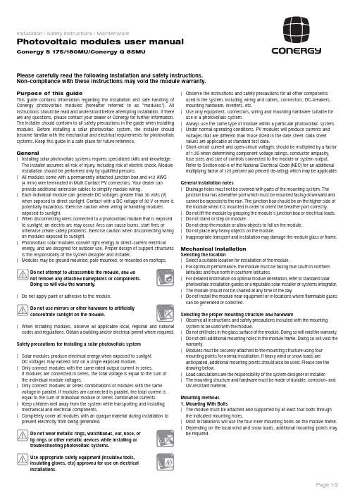
Purp ose of this guideThis guide contains information regarding the installation and safe handling of Conergy photovoltaic modules (hereafter referred to as "modules"). All instructions should be read and understood before attempting installation. If there are any questions, please contact your dealer or Conergy for further information. The installer should conform to all safety precautions in the guide when installing modules. Before installing a solar photovoltaic system, the installer should become familiar with the mechanical and electrical requirements for photovoltaic systems. Keep this guide in a safe place for future reference.General|Installing solar photovoltaic systems requires specialized skills and knowledge.The installer assumes all risk of injury, including risk of electric shock. Module installation should be performed only by qualified persons.|All modules come with a permanently attached junction box and #12 AWG (4mm²) wire terminated in Multi Contact PV connectors. Your dealer canprovide additional extension cables to simplify module wiring.|Each individual module can generate DC voltages greater than 30 volts (V) when exposed to direct sunlight. Contact with a DC voltage of 30V or more is potentially hazardous. Exercise caution when wiring or handling modulesexposed to sunlight.|When disconnecting wires connected to a photovoltaic module that is exposed to sunlight, an electric arc may occur. Arcs can cause burns, start fires orotherwise create safety problems. Exercise caution when disconnecting wiring on modules exposed to sunlight.|Photovoltaic solar modules convert light energy to direct-current electrical energy, and are designed for outdoor use. Proper design of support structures is the responsibility of the system designer and installer.|Modules may be ground mounted, pole mounted, or mounted on rooftops.Do not attempt to disassemble the module, and donot remove any attached nameplates or components.Doing so will void the warranty.|Do not apply paint or adhesive to the module.Do not use mirrors or other hardware to artificiallyconcentrate sunlight on the module.|When installing modules, observe all applicable local, regional and national codes and regulations. Obtain a building and/or electrical permit where required.Safety precautions for installing a solar photovoltaic system|Solar modules produce electrical energy when exposed to sunlight.DC voltages may exceed 30V on a single exposed module.|Only connect modules with the same rated output current in series.If modules are connected in series, the total voltage is equal to the sum of the individual module voltages.|Only connect modules or series combinations of modules with the same voltage in parallel. If modules are connected in parallel, the total current isequal to the sum of individual module or series combination currents.|Keep children well away from the system while transporting and installing mechanical and electrical components.|Completely cover all modules with an opaque material during installation to prevent electricity from being generated.Do not wear metallic rings, watchbands, ear, nose, orlip rings or other metallic devices while installing ortroubleshooting photovoltaic systems.Use appropriate safety equipment (insulated tools,insulating gloves, etc) approved for use on electricalinstallations.|Observe the instructions and safety precautions for all other components used in the system, including wiring and cables, connectors, DC-breakers, mounting hardware, inverters, etc.|Use only equipment, connectors, wiring and mounting hardware suitable for use in a photovoltaic system.|Always use the same type of module within a particular photovoltaic system. |Under normal operating conditions, PV modules will produce currents and voltages that are different than those listed in the date sheet. Data sheetvalues are applicable at standard test data.|Short-circuit current and open-circuit voltages should be multiplied by a factor of 1.25 when determining component voltage ratings, conductor ampacity, fuse sizes and size of controls connected to the module or system output.Refer to Section 690-8 of the National Electrical Code (NEC) for an additional multiplying factor of 125 percent (80 percent de-rating) which may be applicable.General installation notes|Drainage holes must not be covered with parts of the mounting system. The junction box has a breather port which must be mounted facing downward and cannot be exposed to the rain. The junction box should be on the higher side of the module when it is mounted in order to orient the breather port correctly.|Do not lift the module by grasping the module's junction box or electrical leads. |Do not stand or step on module.|Do not drop the module or allow objects to fall on the module.|Do not place any heavy objects on the module.|Inappropriate transport and installation may damage the module glass or frame.Mechanical InstallationSelecting the location|Select a suitable location for installation of the module.For optimum performance, the module must be facing true south in northernlatitudes and true north in southern latitudes.For detailed information on optimal module orientation, refer to standard solarphotovoltaic installation guides or a reputable solar installer or systems integrator.|The module should not be shaded at any time of the day.|Do not install the module near equipment or in locations where flammable gasescan be generated or collected.Observe all instructions and safety precautions included with the mountingsystem to be used with the module.|Do not drill holes in the glass surface of the module. Doing so will void the warranty.|Do not drill additional mounting holes in the module frame. Doing so will void thewarranty.|Modules must be securely attached to the mounting structure using fourmounting points for normal installation. If heavy wind or snow loads areanticipated, additional mounting points should also be used. Please see thedrawing below.|Load calculations are the responsibility of the system designer or installer.|The mounting structure and hardware must be made of durable, corrosion- andUV-resistant material.Mounting methods1.Mounting With Bolts|The module must be attached and supported by at least four bolts throughthe indicated mounting holes.|Most installations will use the four inner mounting holes on the module frame.Depending on the local wind and snow loads, additional mounting points maybe required.Please carefully read the following installation and safety instructions.Non-compliance with these instructions may void the module warranty.Page 1/22.Mounting With Clamping Hardware|If module clamps are used to secure the module, the torque on the clamp bolt should be around 8–10 Nm.| A minimum of four module clamps should be used, two on each long frame side,in the general clamping areas denoted by the wide arrows on the drawing.|Depending on the local wind and snow loads, additional module clamps may be required.All dimensions in mm3.Other|Other mounting methods are acceptable as long as the minimum requirement as described under 2. Mounting with clamping hardware are met.Electrical Installation Grounding|All module frames must be properly grounded.|Observe all local electric codes and regulations.| A bonding or toothed washer is required to make proper and reliable electrical grounding connection with the anodized aluminum frame.|Devices listed and identified for grounding metallic frames of PV modules are permitted to ground the exposed metallic frames of the module to grounded mounting structures. Per NEC 250.136, electrical equipment secured to and in electrical contact with a metal rack or structure provided for its support and grounded by one of the means indicated in 250.134 shall be considered effectively grounded.|Consider using a lay-in lug, rated for outdoor use (IllscoGBL4 DBT or equivalent),if the module grounding conductor is to be larger than #10 AWG.|When using lay-in lugs, the grounding conductor should be inserted into the opening indicated in the figure, and secured using the set screw.General electrical installation|Do not use modules of different configurations in the same system.|This module is supplied with Multi Contact connectors for electrical connections. |Refer to Section 690.31 of the NEC to determine appropriate types and temperature ratings of conductors. Wiring should be #12 AWG, 4mm² (minimum) and must be temperature rated at 90 °C (minimum).|Completely cover system modules with an opaque material to prevent electricity from being generated while disconnecting conductors.|Refer to Sections 690.8 and 310 of the NEC to determine overcurrent, conductor ampacity and size requirements.|In Canada, installation shall be in accordance with CSA C22.1, Safety Standard for Electrical Installations, Canadian Electrical Code, Part 1.|For best performance, ensure that positive and negative DC wires run closely together avoiding loops.WARNING!Electrical shock hazard! Do not touch bare conductors or other potentially energized parts.MaintenanceConergy recommends the following maintenance items to ensure optimum performance of the module:|Clean the glass surface of the module as necessary. Use water and a soft sponge or cloth for cleaning. A mild, non-abrasive cleaning agent can be used if necessary. Do not use dishwasher detergent.|Electrical and mechanical connections should be checked periodically by qualified personnel to verify that they are clean, secure and undamaged.|Check the electrical and mechanical connections periodically to verify that they are clean, secure and undamaged.|Problems should only be investigated by qualified personnel.|Observe the maintenance instructions for all other components used in the system.Shutting down the system|Completely cover system modules with an opaque material to prevent electricity from being generated while disconnecting conductors.|Disconnect system from all power sources in accordance with instructions for all other components used in the system.|The system should now be out of operation and can be dismantled. In doing so, observe the all safety instructions as applicable to installation.Electrical ratings of the concerned modules:S 180MU175MUQ 85MUMaximum Power (P MPP ) 180 W 175 W 85 W Output Tolerance –2/+ 3 %–2/+ 3 %+/- 5 %Rated Voltage (V MPP ) 35.6 V 35.2 V 17.6 V Rated Current (I MPP )5.05 A 4.95 A 4.83 A Open Circuit Voltage (V OC ) 44.4 V 44.2 V 21.9 V Short Circuit Current (I SC ) 5.4 A 5.2 A 5.14 A Maximum System Voltage 600 V 600 V 600 V Maximum Series Fuse Rating 15 A 15 A 15 A Fire ClassCCCThe electrical characteristics are within ±10 % of the indicated values of I , V , and P under Standard Test Conditions (irradiance of 1000 W/m , AM 1.5 spectrum, and a cell temperature of 25°C/77°F)Disclaimer of liabilityBecause the use of this manual and the conditions or methods of installation, operation, use and maintenance of photovoltaic products are beyond Conergy's control, Conergy does not accept responsibility and expressly disclaims liability for loss, damage, or expense arising out of or in any way connected with such installation, operation, use or maintenance. No responsibility is assumed by Conergy for any infringement of patents or other rights of third parties, which may result from use of the PV product. No license is granted by implication or otherwise under any patent or patent rights.The information in this manual is based on Conergy's knowledge and experience and is believed to be reliable, but such information including product specification (without limitations) and suggestions does not constitute a warranty, expressed or implied. Conergy reserves the right to change the manual, the product, the specifications, or product information sheets without prior notice. Information about manufacturer:Conergy Inc.1730 Camino Carlos Rey, Suite 103Santa Fe, NM 87507USAPlease consult your dealer or the manufacturer concerning the warranty of your modules. If you have any further questions, your dealer will gladly assist you.Subject to technical modifications without notice. 2007 © Conergy, Inc.M O D U L _I n s t a l l a t i o n -U L -I M -E N G -0705 | 2007 © Conergy AGPage 2/2。
全黑高密度单面光伏模块商品说明书

ALL-BLACK High density MONO PERC modulePRODUCT CERTIFICATES*HiDM-BlackMORE POWERMaximize the light absorption area, module efficiency up to 20.16 %Low temperature coefficient (Pmax): -0.37 % / °CMORE RELIABLECANADIAN SOLAR INC.545SpeedvaleAvenueWest,Guelph,OntarioN1K1E6,Canada,,*************************ISO 9001:2015 / Quality management systemISO 14001:2015 / Standards for environmental management systemOHSAS 18001:2007 / International standards for occupational health & safetyMANAGEMENT SYSTEM CERTIFICATES*320 W ~ 340 WCS1H-320|325|330|335|340MSUP TO 20.16%Heavy snow load up to 5400 Pa,wind load up to 2400 Pa*Better shading toleranceLower internal current, lower hot spot temperatureCell crack risk limited in small region, enhance the module reliability IEC 61215 / IEC 61730: VDE / CE / MCSUL 1703 / IEC 61215 performance: CEC listed (US) / FSEC (US Florida)UL 1703: CSA / IEC 61701 ED2: VDE / IEC 62716: VDE Take-e-wayAs there are different certification requirements in different markets, please contact your local Canadian Solar sales representative for the specific certificates applicable to the products in the region in which the products are to be used.CANADIAN SOLAR INC. is committed to providing highquality solar products, solar system solutions and services to customers around the world. No. 1 module supplier for quality and performance/price ratio in IHS Module Customer Insight Survey. As a leading PV project developer and manufacturer of solar modules with over 38 GW deployed around the world since 2001.*According to the applicable Canadian Solar Limited Warranty Statement.linear power output warranty*enhanced product warranty on materials and workmanship** For detail information, please refer to Installation Manual.MECHANICAL DATA Specification Data Cell Type Mono-crystalline Dimensions 1700 ˣ 992 ˣ 35 mm (66.9 ˣ 39.1 ˣ 1.38 in)Weight 19.2 kg (42.3 lbs)Front Cover 3.2 mm tempered glass Frame Anodized aluminium alloy J-Box IP68, 3 bypass diodes Cable 4.0 mm² (IEC), 12 AWG (UL)Cable Length 1350 mm (53.1 in) (Including Connector) Connector T4 series or H4 UTX or MC4-EVO2 Per Pallet 30 pieces Per Container (40‘ HQ) 780 piecesTEMPERATURE CHARACTERISTICS SpecificationDataTemperature Coefficient (Pmax) -0.37 % / °C Temperature Coefficient (Voc) -0.29 % / °C Temperature Coefficient (Isc)0.05 % / °C Nominal Module Operating Temperature44±3 °CPARTNER SECTIONRear ViewFrame Cross Section A-AThe specifications and key features contained in this datasheet may deviate slightly from our actual products due to the on-going innovation and product enhancement. Canadian Solar Inc. reserves the right to make necessary adjustment to the information described herein at any time without further notice.Please be kindly advised that PV modules should be handled and installed by qualified people who have professional skills and please carefully read the safety and installation instructions before using our PV modules.CANADIAN SOLAR INC.545SpeedvaleAvenueWest,Guelph,OntarioN1K1E6,Canada,,*************************December 2019. All rights reserved, PV Module Product Datasheet V5.583_ENELECTRICAL DATA | STC*CS1H320MS 325MS 330MS 335MS 340MS Nominal Max. Power (Pmax)320 W325 W 330 W 335 W 340 W Opt. Operating Voltage (Vmp)36.2 V 36.6 V 37.0 V 37.4 V 37.8 V Opt. Operating Current (Imp)8.85 A 8.88 A 8.92 A 8.96 A 9.00 A Open Circuit Voltage (Voc)44.0 V 44.1 V 44.2 V 44.3 V44.5 VShort Circuit Current (Isc)9.41 A 9.45 A9.49 A 9.53 A 9.57 AModule Efficiency 18.98%19.27%19.57%19.86%20.16%Operating Temperature -40°C ~ +85°C Max. System Voltage 1000V (IEC/UL)Module Fire Performance TYPE 1 (UL 1703) or CLASS C (IEC 61730) Max. Series Fuse Rating 15 A Application Classification Class A Power Tolerance0 ~ + 5 W* Under Standard Test Conditions (STC) of irradiance of 1000 W/m 2, spectrum AM 1.5 and cell temperature of 25°C.ELECTRICAL DATA | NMOT*CS1H320MS 325MS 330MS 335MS 340MS Nominal Max. Power (Pmax)236 W240 W 243 W 247 W 251 W Opt. Operating Voltage (Vmp)33.4 V 33.7 V 34.1 V 34.5 V 34.8 V Opt. Operating Current (Imp)7.07 A 7.11 A 7.14 A 7.17 A 7.20 A Open Circuit Voltage (Voc)41.0 V 41.1 V 41.2 V 41.3 V41.5 VShort Circuit Current (Isc)7.60 A7.63 A7.66 A 7.70 A 7.73 A* Under Nominal Module Operating Temperature (NMOT), irradiance of 800 W/m 2, spectrum AM 1.5, ambient temperature 20°C, wind speed 1 m/s.ENGINEERING DRAWING (mm)CS1H-330MS / I-V CURVES5°C 25°C 45°C 65°C1000 W/m 800 W/m 600 W/m 400 W/m200 W/m A A V12111098765432105 10 15 20 25 30 35 40 45 50 V5 10 15 20 25 30 35 40 45 501211109876543210。
godex说明
警告使用者:這是甲類的資訊產品,在居住的環境中使用時,可能會造成射頻干擾,在這種情況下, 使用者會被要求採取某些適當的對策.
EZPi-1000 User’s Manual
4
第 1 章 条码机 .......................................................................... 6
5. Wartungs- und Reparaturarbeiten dürfen aus Sicherheitsgründen nur von autorisierten Personen durchgeführt werden.
6. Bei Wartungs- und Reparaturarbeiten müssen die Sicherheitsvorschriften der zuständigen Berufsverbände und Behörden unbedingt eingehalten werden.
CAUTION Danger of explosion if battery is incorrectly replaced Replace only with the equivalent type recommended by the manufacture. Dispose of used batteries according to the manufacturer’s instructions.
2. Bevor Sie die Geräte ans Stromnetz anschließen, vergewissern Sie Sich, dass die Spannung des Geräts mit der Netzspannung übereinstimmt.
2024年度Cognex培训课件

智能交通领域
实现车辆识别、交通拥堵监测 等任务,提升交通管理和安全
水平。
12
03
图像采集与处理技术
2024/2/2
13
图像采集设备选择及参数设置
相机类型
根据应用场景选择合适的相机类型,如CCD 、CMOS等。
镜头选择
根据拍摄距离和视野范围选择合适的镜头类 型和参数。
2024/2/2
分辨率与像素
根据需求选择合适的分辨率和像素大小,确 保图像清晰度。
光源与照明
合理配置光源和照明条件,以获得高质量的 图像效果。
14
图像处理基本算法介绍
滤波算法
用于去除图像噪声、平滑图像等,如高斯滤 波、中值滤波等。
边缘检测算法
用于检测图像中的边缘信息,如Sobel、 Canny等算子。
学员B
培训过程中,老师讲解得非常详细 ,让我掌握了很多实用的技能和知 识,对今后的工作有很大的帮助。
2024/2/2
学员C
通过与其他学员的交流和分享,我 收获了很多宝贵的经验和建议,也 结识了很多有趣的朋友,激发了我
对机器视觉未来的期待。
学员D
这次培训不仅让我学到了专业知识 ,还让我领略了Cognex的企业文 化和团队精神,让我更加坚定了在
02
图像采集实验
使用选定的设备和参数进行实际图 像采集操作。
结果展示与讨论
展示处理结果并讨论不同算法和参 数对结果的影响。
04
17
04
机器视觉检测技术应 用
2024/2/2
18
缺陷检测原理及实现方法
缺陷检测基本原理
通过对比分析产品的实际图像与标准图像, 发现并定位表面缺陷。
cognex视觉培训教程(2024)

22
案例二:机器人视觉引导定位抓取
应用场景
在自动化生产线或仓储物流等场景中,需要机器人对物体进行抓取和搬运。
2024/1/30
视觉系统应用
通过搭载视觉系统的工业相机对物体进行拍照,利用图像处理技术识别出物体的位置和姿 态信息,并将这些信息传递给机器人控制器,从而引导机器人进行准确的抓取和搬运。
优势
视觉系统可以实现全面、准确的质量 检测和控制,提高产品质量和生产效 率,降低不良品率和成本。
2024/1/30
25
2024/1/30
06
视觉系统发展趋势及挑战
26
深度学习在视觉系统中的应用前景
提升图像识别准确率
实现复杂场景下的目标检测
深度学习技术可以处理复杂的背景、光照变化和遮 挡等问题,实现在复杂场景下的目标检测。
视觉系统可以提高机器人的定位精度和抓取效率,减少人工干预和操作难度。
23
案例三:智能仓储管理系统中的条码识别
应用场景
在智能仓储管理系统中,需要对货物进行快速、准确的识别和分类。
2024/1/30
视觉系统应用
通过搭载视觉系统的工业相机对货物上的条码进行拍照,利用图像处理技术识别出条码信息,并将这些信息 传递给仓储管理系统,从而实现货物的快速入库、出库和盘点等操作。
2024/1/30
该软件支持多种操作系统 和硬件设备,具有良好的 兼容性和可扩展性。
Cognex视觉软件提供了丰 富的算法库和工具,方便 用户进行二次开发和定制 化应用。
13
图像采集与处理功能
图像采集
支持多种图像采集设备,如相机 、扫描仪等,可实现高质量的图 像采集。
图像处理
提供多种图像处理算法,如滤波 、增强、二值化等,用于改善图 像质量和提取特征。
- 1、下载文档前请自行甄别文档内容的完整性,平台不提供额外的编辑、内容补充、找答案等附加服务。
- 2、"仅部分预览"的文档,不可在线预览部分如存在完整性等问题,可反馈申请退款(可完整预览的文档不适用该条件!)。
- 3、如文档侵犯您的权益,请联系客服反馈,我们会尽快为您处理(人工客服工作时间:9:00-18:30)。
用
应
业
工
太阳能光伏(PV)电池及模块
每一步都充满信心
为最小化晶片损坏而采用视觉系统代替机械原理进行对准、从晶片至安装过程中进行产品跟踪,接受直接反馈解决产品与工艺问题,视觉技术为加工过程的每个步骤增加价值。
这就是康耐视——在全世界范围内安装超过500,000套产品——自1981年以来一直是行业领先者。
与独立的检查系统相比,灵活、功能强大的康耐视视觉产品提供的价值更高而成本更低。
PV生产用机器视觉…现在和未来
随着太阳能工业的重心从数量转变为质量,并且工艺变得更加复杂,康耐视丰富的视觉工具为其提供先进的机器视觉技术,以实现最为可靠的结果。
最新的太阳能工具箱(Solar Toolbox TM)为用户提供一套预先配置的工具,进行太阳能电池生产中最为常见的视觉检查。
除太阳能工具箱之外,康耐视还提供当今最为先进的视觉工具,例如PatMax®、PatInspect®以及IDMax®,可以处理在太阳能电池生产中的多种应用需求。
太阳能工具箱
从基本的软件库开始,或使用我们预先配置好的校准与检查工具。
康耐视功能强大的VisionPro®软件专门提供了太阳能工具箱,为用户提供成套工具,以解决八个最为普遍的太阳能生产质量问题:边缘破片检查、小孔检测、背面印刷定位及检查、正面汇流条定位、正面栅线痕检查、颜色均匀度检查以及裂纹检查。
PatMax
进行目标定位的关键工具是PatMax,它是元件定位的专利技术软件工具。
PatMax采用我们专有的几何图案甄别技术,可在极具挑战性的环境下进行晶片、电池以及模块的特征定位,具有无与伦比的准确度及可靠性。
色彩视觉(Color Vision)
无论是进行颜色分选或是检验防反射涂层的颜色均匀性,康耐视色彩工具都可以检测并测量颜色特征。
色彩搜查柱状图可以方便地进行培训,以提供关键的色彩特征,这是灰度级视觉技术无法实现的。
PatInspect
PatInspect采用专利算法技术,元件定位与缺陷检测一步到位,即使是处于元件边线上的瑕疵也能可靠地检测,而其它的技术对此则很难获得可靠的结果。
PatInspect可在不同的晶片涂层及照明条件下进行工作。
IDMax
功能强大的解码软件工具IDMax,设计用于阅读最富挑战性的代码。
IDMax可靠地读取即使是退化的、反射性的或者低对比度的标记,使整个晶片至面板的可追溯性成为可能。
除了我们众多的基于视觉系统的产品之外,康耐视还提供全球最为广泛的视觉专家网络。
其在20多个国家设有办事处,遍及美洲、欧洲及亚洲——以及超过300家本地经销商与合作伙伴网络——康耐视可提供全球化的本地支
持。
太阳能工具箱内容边缘破片检查
小孔检测
背面印刷定位
背面印刷检查
正面汇流条定位
正面栅线痕检查
颜色均匀度检验
裂纹检查
始于晶片的挑战...
硅晶体检查
测量硅晶体的生长情
况,提供数据以帮助
确定晶体外观与晶片
产率之间的关系。
缺陷检查
检查边缘碎裂、锯齿状痕迹,以及晶片上的轮廓缺陷。
防反射(AR)涂层检查检查晶片/电池上防反射涂层的厚度以及颜色均匀性。
晶片检查
检查晶片的着色、污染以及网状图案情况,确保尺寸大小以避免加工翘曲的晶片。
晶片及PV电池的识别在整个生产过程中可靠地识别所有的代码,进行晶片及PV电池跟踪。
...与电池生产同行...
电池方向检测
监控太阳能电池,在混合
应用阶段前确保其正确的
直立方向。
电池颜色分选
根据轻微的颜色差异
进行检查,并分类太阳能电池,根据颜色的不一致情况将电池分级。
背面印刷定位与检查
检查汇流条的位置、宽度及其
间的距离,并检查栅线的连续
性。
机器人引导
在太阳电池板制造工
艺中为机器人引导发
送位置信息。
电池缺陷检查
检查电池的碎裂情况,确保在加工前丢弃有缺陷的电池。
丝网印刷定位
对太阳能电池的丝网印
刷进行精确定位。
激光边线隔离
校准电池并沿晶片边缘检
查边缘凹槽切口,隔离发
射极和电池背面。
正面印刷定位
检查线条的轮廓中断、连
续性情况以及过多的焊接
剂情况,确保线条平行并
且位置正确。
...随模块组装结束
电池片间隔
确保成品模块中的电池片间隔一致。
标号/基线定位与检查
确定PV 电池的中心,将机械接触的需求降至最低,并检查电池的缺陷情况,同时验证每条线的连续性以及正确组装情况。
面板组装验证
对面板组件进行最后的质量检查,确保准确的电池片间隔、构造以及元件位置情况。
框架检查
确保在铝制框架上有螺丝,并且处于正确的位置。
连接器检查
确保使用焊接剂,并且其在正确的位置上,以连接电气插头和太阳能电池组件。
太阳能电池板的可追溯性
通过读取电池板上直接标记的二维(数据矩阵)代码,在生产以及使用过程中跟踪各个模块。
康耐视公司总部
康耐视公司
One Vision Drive
纳题克郡
MA 01760-2059
美国
电话: 508-650-3000传真: 508-650-3344美国
马萨诸塞州的纳题克郡 508-650-3000
田纳西州,纳什维尔 615-844-6158
密歇根州,底特律市 248-668-5100
伊利诺斯州,芝加哥市 630-649-6300
加利福尼亚州, Mountain View
650-969-4812
拉丁美洲
墨西哥,蒙特雷 +52 81 5030-7258
墨西哥,墨西哥城+52 55 2789-7839
欧洲
法国 +33 1 4777 1550
德国 +49 721 6639 0
爱尔兰 +353 1 825 4420
意大利 +39 02 6747 1200
荷兰 +31 402 668 565
西班牙 +34 93 445 67 78
瑞典 +46 21 14 55 88
瑞士 +41 71 313 06 05
英国 +44 1908 206 000
加拿大 +905-634-2726
日本+81 3 5977 5400
亚洲
中国 +86 21 6361 6767
韩国 +82 2 539 9047
新加坡 +65 632 55 700
台湾 +886 3 578 0060
全世界很多公司都依赖康耐视视觉应用,使其质量达到最优化,并降低成本。
©2009年,康耐视公司版权所有。
Cognex、Checker、Cognex Vision Solutions、DataMan、IDMax、In-sight、PatInspect、PatMax以及VisionPro是康耐视公司的注册商标,Solar Toolbox是康耐视公司的商标。
所有其它商标为各自相应公司所有。
2009年09月印制。