UPSD3213AV-40U6T中文资料
UPS说明书技术参数

不间断电源u n i n t e r r u p t i b l e p o w e rs u p p l yU P S(6···250)K V A产品使用说明书目录1.产品介绍---------------------------------------------2 2.操作要求---------------------------------------------2 3.注意事项---------------------------------------------2 4.工作原理---------------------------------------------3 5.前板介绍---------------------------------------------7 6.安装---------------------------------------------------87. 主要技术指标---------------------------------------118. 告警说明---------------------------------------------159. UPS启动程序-------------------------------------17 10.UPS维修关机程序------------------------------17 11. 紧急关机程序--------------------------------------17 12.前显示板说明-------------------------------------18 13.并机系统启动操作步骤-------------------------21 14.并机系统关机步骤---------- --------------------2215. 并机系统紧急关机步骤--------------------------2216. 附页—开机注意事项----------------------------- 241.产品介绍三三系列三进三出全数字化UPS,是采用先进的微电子、电力电子、数字控制技术,集数字化、信息化、网络化为一体的高智能型产品,具有强大的信息采集系统、信号处理系统、监测系统和完善的保护系统。
uPSD3333D-40U6中文资料

1/9DATA BRIEFINGJanuary 2005For further information contact your local ST sales office.uPSD33xxTurbo SeriesFast 8032 MCU with Programmable LogicFEATURES SUMMARY■FAST 8-BIT TURBO 8032 MCU, 40MHz –Advanced core, 4-clocks per instruction –10 MIPs peak performance at 40MHz (5V)–JTAG Debug and In-SystemProgramming–Branch Cache & 6 instruction PrefetchQueue–Dual XDATA pointers with auto incr & decr –Compatible with 3rd party 8051 tools ■DUAL FLASH MEMORIES WITH MEMORY MANAGEMENT–Place either memory into 8032 programaddress space or data address space –READ-while-WRITE operation for In-Application Programming and EEPROM emulation–Single voltage program and erase–100K guaranteed erase cycles, 15-yearretention■CLOCK, RESET, AND SUPPLY MANAGEMENT–SRAM is Battery Backup capable–Flexible 8-level CPU clock divider register –Normal, Idle, and Power Down Modes –Power-on and Low Voltage resetsupervisor–Programmable Watchdog Timer ■PROGRAMMABLE LOGIC, GENERAL PURPOSE–16 macrocells–Create shifters, state machines, chip-selects, glue-logic to keypads, panels, LCDs, others■COMMUNICATION INTERFACES–I 2C Master/Slave controller, 833KHz –SPI Master controller, 10MHz–Two UARTs with independent baud rate –IrDA protocol support up to 115K baud –Up to 46 I/O, 5V tolerant on 3.3VuPSD33xxV■A/D CONVERTER–Eight Channels, 10-bit resolution, 6µs ■TIMERS AND INTERRUPTS–Three 8032 standard 16-bit timers–Programmable Counter Array (PCA), six16-bit modules for PWM, CAPCOM, and timers–8/10/16-bit PWM operation–11 Interrupt sources with two externalinterrupt pins■OPERATING VOLTAGE SOURCE (±10%)–5V devices use both 5.0V and 3.3Vsources– 3.3V devices use only 3.3V sourceuPSD33xx2/9Table 1. Device SummaryPart Number 1st Flash (bytes)2nd Flash (bytes)SRAM (bytes)GPIO 8032 Bus V CC V DD Pkg.Temp.uPSD3312D-40T664K 16K 2K 37No 3.3V 5.0V TQFP52–40°C to 85°C uPSD3312DV-40T664K 16K 2K 37No 3.3V 3.3V TQFP52–40°C to 85°C uPSD3333D-40T6128K 32K 8K 37No 3.3V 5.0V TQFP52–40°C to 85°C uPSD3333DV-40T6128K 32K 8K 37No 3.3V 3.3V TQFP52–40°C to 85°C uPSD3333D-40U6128K 32K 8K 46Yes 3.3V 5.0V TQFP80–40°C to 85°C uPSD3333DV-40U6128K 32K 8K 46Yes 3.3V 3.3V TQFP80–40°C to 85°C uPSD3334D-40U6256K 32K 8K 46Yes 3.3V 5.0V TQFP80–40°C to 85°C uPSD3334DV-40U6256K 32K 8K 46Yes 3.3V 3.3V TQFP80–40°C to 85°C uPSD3354D-40T6256K 32K 32K 37No 3.3V 5.0V TQFP52–40°C to 85°C uPSD3354DV-40T6256K 32K 32K 37No 3.3V 3.3V TQFP52–40°C to 85°C uPSD3354D-40U6256K 32K 32K 46Yes 3.3V 5.0V TQFP80–40°C to 85°C uPSD3354DV-40U6256K32K32K46Yes3.3V3.3VTQFP80–40°C to 85°CuPSD33xx SUMMARY DESCRIPTIONThe Turbo uPSD33xx Series combines a powerful 8051-based microcontroller with a flexible memory structure, programmable logic, and a rich periph-eral mix to form an ideal embedded controller. At its core is a fast 4-cycle 8032 MCU with a 6-byte instruction prefetch queue (PFQ) and a 4-entry ful-ly associative branching cache (BC) to maximize MCU performance, enabling loops of code in smaller localities to execute extremely fast.Code development is easily managed without a hardware In-Circuit Emulator by using the serial JTAG debug interface. JTAG is also used for In-System Programming (ISP) in as little as 10 sec-onds, perfect for manufacturing and lab develop-ment. The 8032 core is coupled to Programmable System Device (PSD) architecture to optimize the 8032 memory structure, offering two independent banks of Flash memory that can be placed at vir-tually any address within 8032 program or data ad-dress space, and easily paged beyond 64K bytes using on-chip programmable decode logic. Dual Flash memory banks provide a robust solution for remote product updates in the field through In-Ap-plication Programming (IAP). Dual Flash banks also support EEPROM emulation, eliminating the need for external EEPROM chips. General pur-pose programmable logic (PLD) is included to build an endless variety of glue-logic, saving exter-nal logic devices. The PLD is configured using the software development tool, PSDsoft Express, available from the web at /psm, at no charge. The uPSD33xx also includes supervisor functions such as a programmable watchdog timer and low-voltage reset.3/9uPSD33xxPIN DESCRIPTIONSNote: 1.For 5V applications, V DD must be connected to a 5.0V source. For 3.3V applications, V DD must be connected to a 3.3V source.2.These signals can be used on one of two different ports (Port 1 or Port 4) for flexibility. Default is Port1.3.V REF and 3.3V AV CC are shared in the 52-pin package only. ADC channels must use AV CC as V REF for the 52-pin package.4/9uPSD33xxNote: 1.For 5V applications, V DD must be connected to a 5.0V source. For 3.3V applications, V DD must be connected to a 3.3V source.2.These signals can be used on one of two different ports (Port 1 or Port 4) for flexibility. Default is Port1.5/9uPSD33xx6/9Table 2. Major ParametersParameterTest Conditions/Comments5.0V Value 3.3V Value Unit Operating Voltage – 4.5 to 5.5 (PSD);3.0 to 3.6 (MCU)3.0 to 3.6(PSD and MCU)V Operating Temperature ––40 to 85–40 to 85°C MCU Frequency8MHz (min) for I 2C 1 Min, 40 Max1 Min, 40 MaxMHz Active Current, Typical (20% of PLD used; 25°C operation)40MHz Crystal, T urbo 5040mA 40MHz Crystal, Non-Turbo 4838mA 8MHz Crystal, Turbo 2118mA 8MHz Crystal, Non-Turbo 108mA Idle Current, Typical(20% of PLD used; 25°C operation)40MHz Crystal divided by 2048internally.All interfaces are disabled.1611mA Standby Current, Typical Power-down Mode needs reset to exit.140120µA SRAM Backup Current, T ypical If external battery is attached.0.50.5µA I/O Sink/Source Current,Ports A, B, C, and D V OL = 0.45V (max);V OH = 2.4V (min)I OL = 8 (max);I OH = –2 (min)I OL = 4 (max);I OH = –1 (min)mA I/O Sink/Source Current,Port 4V OL = 0.6V (max);V OH = 2.4V (min)I OL = 10 (max);I OH = –10 (min)I OL = 10 (max);I OH = –10 (min)mA PLD Macrocells For registered or combinatorial logic 1616–PLD Inputs Inputs from pins, feedback,or MCU addresses6969–PLD OutputsOutput to pins or internal feedback 1818–PLD Propagation Delay, Typical, Turbo ModePLD input to output1522nsuPSD33xx PART NUMBERINGTable 3. Ordering Information SchemeExample:uPSD3334D V–40U6TDevice TypeuPSD = Microcontroller PSDFamily33 = T urbo coreSRAM Size1 = 2Kbyte3 = 8Kbyte5 = 32KbyteMain Flash Memory Size2 = 64Kbyte3 = 128Kbyte4 = 256KbyteIP MixD = IP Mix: I2C, SPI, UART (2), IrDA, ADC, Supervisor, PCAOperating Voltageblank = V CC = 4.5 to 5.5VV = V CC = 3.0 to 3.6VSpeed–40 = 40MHzPackageT = 52-pin TQFPU = 80-pin TQFPTemperature Range6 = –40 to 85°CShipping Optio nTape & Reel Packing = TFor a list of available options (e.g., Speed, Package) or for further information on any aspect of this device, please contact the ST Sales Office nearest to you.7/9uPSD33xxREVISION HISTORYTable 4. Document Revision HistoryDate Version Revision Details July 1, 2003 1.0First Issue14-Sep-04 2.0Reformatted; updated with version 4.0 datasheet 21-Jan-05 3.0Updated with version 6.0 datasheet8/9uPSD33xx Information furnished is believed to be accurate and reliable. However, STMicroelectronics assumes no responsibility for the consequencesof use of such information nor for any infringement of patents or other rights of third parties which may result from its use. No license is granted by implication or otherwise under any patent or patent rights of STMicroelectronics. Specifications mentioned in this publication are subject to change without notice. This publication supersedes and replaces all information previously supplied. STMicroelectronics products are notauthorized for use as critical components in life support devices or systems without express written approval of STMicroelectronics.The ST logo is a registered trademark of STMicroelectronics.All other names are the property of their respective owners© 2005 STMicroelectronics - All rights reservedSTMicroelectronics group of companiesAustralia - Belgium - Brazil - Canada - China - Czech Republic - Finland - France - Germany - Hong Kong - India - Israel - Italy - Japan - Malaysia - Malta - Morocco - Singapore - Spain - Sweden - Switzerland - United Kingdom - United States of America9/9。
UPS输入输出配电规格

__________________________________________________
U P S输入输出配电规
格
__________________________________________________
附件一:
山特UPS输入输出配电规格表
__________________________________________________
配线注意事项:
➢所有线材两端应有接线端子,且符合安规;
➢并机时每台都需要配一个市电输入开关和输出开关;
➢建议火、零、地线要用有色线按标准区分开;
__________________________________________________
➢零线不要经过空气开关;
➢零地电压建议在2V以下,否则可能影响系统正常运行或对人身安全构成危险;
➢地线勿与避雷接地一起;
➢请使用不带漏电保护功能的输入配电开关,电池组至UPS之间应安装直流开关;
➢3A3 UPS采用正负电池架构,一组电池为40节电池串联,中间(第二十节电池与第二十一节电池相联处)引出一条中线,加上首、尾的引出线一共有3条线与UPS接线排相连。
电池组正端与电池组中线之间的电池称为正电池,电池组负端与电池组中线之间的电池称为负电池。
后附电池接线图。
__________________________________________________
➢表中给出了A系列UPS不同模组数量时的配线标准,当用户以后增加模组时,需要参考本配线标准,重新配线。
__________________________________________________。
UPS说明书
PMU不间断电源(UPS)使用说明书河南铭诺电气设备有限公司一、简介1.1前言PMU--系列工频在线式UPS电源是为了保障计算机服务器、网络电子设备、精密电子仪器、自动化电气设备等系列电子、电气设备高效安全运行而精心设计的高可靠性的不间断电源设备。
PMU—系列UPS电源产品能安全排除市电(AC)电网如:市电中断(Power Fil)、暂态过电压(Switching Transients)、电压下降(Power Sags)、电涌(Power Surges)、高压脉冲(High V oltage Spakes)、电线噪声(Electrical Line Noise)、频率偏移(Frepuency Variatuon)、持续低电压(Brownout)等故障,并能为电子、电气设备提供纯正弦波的电源,保障电子、电气设备高效、安全运行。
该系列UPS电源采用了国际先进SPWM脉宽调制技术,并用了高性能IGBT及SCR的完美结合技术,精心高标准设计、高标准制造而成。
该系列UPS电源稳定、可靠的完美品质赢得了广大国内外客户的青睐,从而成为选用率最高的在线式UPS不间断电源。
1.2注意事项本说明书能让您很容易地操作及维护本系统。
为使本系统能充分发挥其功能,请注意以下事项:1.在使用前务必详阅此说明书。
2.遵照指示步骤,依法操作。
3.机器搬运时应小心轻放。
4.请依照说明书上相关条款进行安装、使用和维护。
5.系统内部有危险电压,请勿打开机盖,避免造成人员触电伤害或系统损坏。
6.避免超负载使用,以免造成市电断电后UPS出现掉电现象。
7.请妥善保存该说明书,以供日后参考用。
8.机器若有异常现象,请依据「异常处理程序」处理。
9.请保持UPS表面清洁、干净。
二、安全1.为了降低设备负载接地不良而引起的电击危险,在连接RS232 SNMP接口时,应将市电输入电源、旁路输入电源断开,只有在连接了全部信号接头后才能闭合市电输入电源和旁路输入电源。
TOBTAK AHA全系列UPS中文说明书 A2
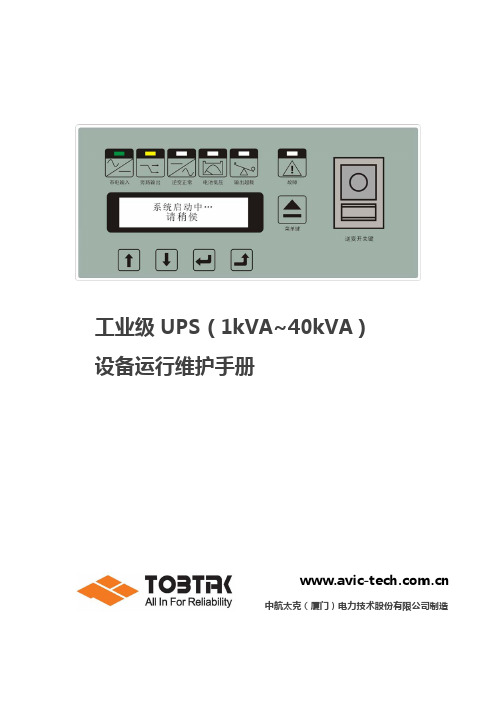
工业级UPS(1kVA~40kVA)设备运行维护手册中航太克(厦门)电力技术股份有限公司制造目录第1章简介 (1)1.1前言 (1)1.2产品特点 (1)1.3安全指示 (1)第2章外型结构与功能说明 (2)2.1操作面板说明 (2)2.2外观说明 (3)2.2.1 1KV A~3KV A 直立式外观图 (3)2.2.2 1KV A~3KV A 机架式外观图 (4)2.2.3 4KV A~6KV A 直立式外观图 (5)2.2.4 4KV A~6KV A 机架式外观图 (5)2.2.5 8KV A~15KV A 直立式外观图 (6)2.2.6 8KV A~15KV A 机架式外观图 (6)2.2.7 20KV A~40KV A 直立式外观图 (7)第3章安装说明 (9)3.1开箱检查 (9)3.2搬运或移动 (9)3.3摆置 (9)第4章安装方法 (11)4.1端子连接 (11)4.1.1 1KV A~3KV A (11)4.1.2 4KV A~6KV A (12)4.1.3 8KV A~15KV A (13)4.1.4 20KV A~40KV A (14)4.2输入与输出 (14)第5章操作程序 (17)5.1开机操作程序 (17)5.1.1 第一次开机前准备工作 (17)5.1.2 第一次开机操作程序 (17)5.2维修旁路断路器(SW6)的操作 (21)5.3故障机的退出系统与并入系统时的操作 (22)第6章系统运行模式 (23)6.1UPS系统架构图 (23)6.2系统运行模式 (23)6.2.1 正常运行模式 (23)6.2.2 直流供电模式 (23)6.2.3 旁路供电模式 (24)6.2.4 维修旁路模式 (24)6.3串联备份系统 (25)6.4并联冗余系统 (26)第7章状况处理 (27)7.1符号代表意义 (27)7.2UPS运行状况显示及不正常时的处理方式 (27)第8章 UPS的维护与保养 (32)8.1注意事项 (32)8.2维护与保养 (32)第9章通讯说明 (33)9.1通讯接口 (33)9.2干接点外观及功能说明 (34)第10章主要技术规格 (35)10.11KV A~3KV A技术规格 (35)10.24KV A~6KV A技术规格 (36)10.38KV A~15KV A技术规格 (37)10.420KV A~40KV A技术规格 (38)第11章并机系统 (39)11.1并机安装 (39)11.2并机接线示意图 (39)11.2.1 1KV A~3KV A (39)11.2.2 4KV A~6KV A (40)11.2.3 8KV A~15KV A (42)11.2.4 20KV A~40KV A (45)第12章 MODBUSRTU-A VICTECH通讯协议 (46)12.1概述 (46)12.2参考文献 (46)12.3帧结构 (46)12.4命令解释 (46)12.4.1 01功能码 (46)12.4.2 03功能码 (47)12.5模拟量地址定义 (48)12.6开关量地址定义 (50)制造商保留对技术及产品规格进行修改的权力,恕不另行通知。
UPS电源系统维护手册要点

UPS电源系统维护UPS电源系统由4部分组成:整流、储能、变换和开关控制。
其系统的稳压功能通常是由整流器完成的,整流器件采用可控硅或高频开关整流器,本身具有可根据外电的变化控制输出幅度的功能,从而当外电发生变化时(该变化应满足系统要求),输出幅度基本不变的整流电压。
净化功能由储能电池来完成,由于整流器对瞬时脉冲干扰不能消除,整流后的电压仍存在干扰脉冲。
储能电池除可存储直流直能的功能外,对整流器来说就象接了一只大容器电容器,其等效电容量的大小,与储能电池容量大小成正比。
由于电容两端的电压是不能突变的,即利用了电容器对脉冲的平滑特性消除了脉冲干扰,起到了净化功能,也称对干扰的屏蔽。
频率的稳定则由变换器来完成,频率稳定度取决于变换器的振荡频率的稳定程度。
开关K1、K5是系统工作开关,K4是主机自检故障后的自动旁路开关,K3则是检修旁路开关。
0K^ UPS电源系统主要分两大部分,主机和储能电池。
额定输出功率的大小取决于主机部分,并与负功属那种性质有关,因为UPS电源对不同性能的负载驱动能力不同,通常负载功率应满足UPS电源70%的额定功率。
储能电池容量的选取当负载功率确定后主要取决其后备时间的长短,这个时间因各站情况不同而不同,主要由备用电源的接入时间来定,通常在几分钟或几个小时不等。
另外储能电池的容量随着时间会逐渐降低,考虑到寿命终止时储能电池容量下降到50%并留有一定的余量。
-?汕头空管论坛--汕头空管论坛,欢迎大家畅所欲言:)>]1 使用注意事项3UPS电源系统因其智能化程度高,储能电池采用了免维护蓄电池,这虽给使用带来了许多便利,但在使用过程中还应在多方面引起注意,才能保证使用安全。
0(1)UPS电源主机对环境温度要求不高,+5℃~40℃都能正常工作,但要求室内清洁,少尘,否则灰尘加上潮湿会引起主机工作紊乱。
储能蓄电池则对温度要求较高,标准使用温度为25℃,平时不能超过+15℃~+30℃。
UPS使用说明

功率因数
0.8
过载能力
105%~125%,1分钟后转旁路,30分钟后断输出;125%~135%, 30秒后转旁路,1分钟后断输出;>135%,0.1秒后转旁路
峰值因数
3:1
失真度
THD<2% (线性满载)
蓄电池(电池在高温下使用,寿命会急剧下降)
后备时间
4分钟 (满
载)
取决于 3分钟 外接电 (满
池容量 载)
3、控制面板 ……………………………………………………………………………… 17 4、操作 …………………………………………………………………………………… 18
4.1 开机 ……………………………………………………………………………… 18 4.2 关机 ……………………………………………………………………………… 19 5、电池维护与保养 ……………………………………………………………………… 20 6、维护 …………………………………………………………………………………… 20 7、面板灯号显示与工作状态对应表 …………………………………………………… 22 8、维修保证 ……………………………………………………………………………… 23
3. 山特所有产品机身上均贴有“电子监管码”(“电子监管码”是国家质检总局为打
击假货推行的一种产品身份识别码)。
4. 消费者可以通过以下途径对产品电子监管码进行查验,并可通过“中国产品质量电
子监管网”平台进行投诉、举报。
查询方式: 网站查询:登陆(中国产品质量电子监管网),输入监管码进行 查询。 电话查询:95001111(未开通地区可拨打010-95001111)。 短信查询:将监管码发送至106695001111(移动、联通均可)。 如有疑问,可以拨打电话95001111或登陆 点击“消费者通道”进 行举报投诉。
艾默生UPS用户手册
艾默生网络能源有限公司 地址:深圳市南山区科技工业园科发路一号 邮编:518057 公司网址: 客户服务投诉热线:0755-86010800 E-mail:info@
重要提示
¾ 本手册涉及艾默生 HIPULSE U 系列 UPS 单机及并机系统的相关安装与运行资料,请在安装前详细阅读本手册 的有关章节。
¾ UPS 必须经厂家或其代理商指定的工程师调试后,才能使用。否则,由此引起的 UPS 损坏,不属保修范围。 ¾ HIPULSE U 系列 UPS 只作商业/工业用途,不可用作任何生命支持设备的电源。
型号 HIPULSE U/120/S/6P HIPULSE U/160/S/6P HIPULSE U/160/S/12P HIPULSE U/200/S/6P HIPULSE U/200/S/12P HIPULSE U/300/S/6P HIPULSE U/300/S/12P HIPULSE U/400/S/6P HIPULSE U/400/S/12P
电池 电池厂家提供了使用大组电池或在其附近所应遵守的注意事项,这些注意事项在任何时候都应遵守。并且应特别注意关于当地 环境条件的相关建议及提供防护工作服,急救设备和消防设备的相关规定。
该警告标识代表所有人身安全指示。
目录
第一章 概述 ........................................................................................................................................................................ 1
- 1、下载文档前请自行甄别文档内容的完整性,平台不提供额外的编辑、内容补充、找答案等附加服务。
- 2、"仅部分预览"的文档,不可在线预览部分如存在完整性等问题,可反馈申请退款(可完整预览的文档不适用该条件!)。
- 3、如文档侵犯您的权益,请联系客服反馈,我们会尽快为您处理(人工客服工作时间:9:00-18:30)。
µPSD323XFlash Programmable System Devices with8032Microcontroller Core and64Kbit SRAM FEATURES SUMMARYs TheµPSD323X Devices combine a Flash PSD architecture with an8032microcontroller core.TheµPSD323X Devices of Flash PSDs feature dual banks of Flash memory,SRAM,general purpose I/O and programmable logic,supervi-sory functions and access via USB,I2C,ADC, DDC and PWM channels,and an on-board 8032microcontroller core,with two UARTs, three16-bit Timer/Counters and two External Interrupts.As with other Flash PSD families,the µPSD323X Devices are also in-system pro-grammable(ISP)via a JTAG ISP interface.s Large8KByte SRAM with battery back-up options Dual bank Flash memories–128KByte or256KByte main Flash memory –32KByte secondary Flash memorys Content Security–Block access to Flash memorys Programmable Decode PLD for flexible address mapping of all memories within8032space.s High-speed clock standard8032core(12-cycle) s USB Interface(some devices only)s I2C interface for peripheral connectionss5Pulse Width Modulator(PWM)channelss Analog-to-Digital Converter(ADC)s Standalone Display Data Channel(DDC)s Six I/O ports with up to50I/O pinss3000gate PLD with16macrocellss Supervisor functions with Watchdog Timers In-System Programming(ISP)via JTAGs Zero-Power Technologys Single Supply Voltage–4.5to5.5V–3.0to3.6V Figure1.52-lead,Thin,Quad,Flat Package Figure2.80-lead,Thin,Quad,Flat PackageTQFP52(T)TQFP80(U)元器件交易网1/176 November2002元器件交易网µPSD323XTABLE OF CONTENTSSUMMARY DESCRIPTION (11)µPSD323X Devices Product Matrix(Table1.) (12)TQFP52Connections(Figure3.) (12)TQFP80Connections(Figure4.) (13)80-Pin Package Pin Description(Table2.) (14)52PIN PACKAGE I/O PORT (16)ARCHITECTURE OVERVIEW (17)Memory Organization (17)Memory Map and Address Space(Figure5.) (17)Registers (17)8032MCU Registers(Figure6.) (17)Configuration of BA16-bit Registers(Figure7.) (18)Stack Pointer(Figure8.) (18)PSW(Program Status Word)Register(Figure9.) (19)Program Memory (19)Data memory (19)RAM (19)Interrupt Location of Program Memory(Figure10.) (19)XRAM-DDC (19)XRAM-PSD (19)SFR (20)RAM Address(Table3.) (20)Addressing Modes (20)Direct Addressing(Figure11.) (20)Indirect Addressing(Figure12.) (20)Indexed Addressing(Figure13.) (21)Arithmetic Instructions (21)Arithmetic Instructions(Table4.) (22)Logical Instructions (22)Logical Instructions(Table5.) (23)Data Transfers (24)Data Transfer Instructions that Access Internal Data Memory Space(Table6.) (24)Shifting a BCD Number Two Digits to the Right(using direct MOVs:14bytes)(Table7.) (25)Shifting a BCD Number Two Digits to the Right(using direct XCHs:9bytes)(Table8.) (25)Shifting a BCD Number One Digit to the Right(Table9.) (25)Data Transfer Instruction that Access External Data Memory Space(Table10.) (26)Lookup Table READ Instruction(Table11.) (26)Boolean Instructions (27)Boolean Instructions(Table12.) (27)Relative Offset (27)2/176元器件交易网µPSD323XJump Instructions (28)Unconditional Jump Instructions(Table13.) (28)Machine Cycles (29)Conditional Jump Instructions (29)State Sequence inµPSD323X Devices(Figure14.) (30)µPSD3200HARDWARE DESCRIPTION (31)µPSD323X Devices Functional Modules(Figure15.) (31)MCU MODULE DISCRIPTION (32)Special Function Registers (32)SFR Memory Map(Table15.) (32)List of all SFR(Table16.) (33)PSD Module Register Address Offset(Table17.) (37)INTERRUPT SYSTEM (39)External Int0 (39)Timer0and1Interrupts (39)Timer2Interrupt (39)I2C Interrupt (39)External Int1 (39)DDC Interrupt (39)USB Interrupt (39)USART Interrupt (40)Interrupt System(Figure16.) (40)SFR Register(Table18.) (41)Interrupt Priority Structure (41)Interrupts Enable Structure (41)Priority Levels(Table19.) (41)Description of the IE Bits(Table20.) (41)Description of the IEA Bits(Table21.) (42)Description of the IP Bits(Table22.) (42)Description of the IPA Bits(Table23.) (42)How Interrupts are Handled (43)Vector Addresses(Table24.) (43)POWER-SAVING MODE (44)Idle Mode (44)Power-Down Mode (44)Power-Saving Mode Power Consumption(Table25.) (44)Power Control Register (44)Pin Status During Idle and Power-down Mode(Table26.) (44)Description of the PCON Bits(Table27.) (44)Idle Mode (44)3/176元器件交易网µPSD323XI/O PORTS(MCU Module) (46)I/O Port Functions(Table28.) (46)P1SFS(91H)(Table29.) (46)P3SFS(93H)(Table30.) (46)P4SFS(94H)(Table31.) (46)PORT Type and Description (47)PORT Type and Description(Part1)(Figure17.) (47)PORT Type and Description(Part2)(Figure18.) (48)OSCILLATOR (49)Oscillator(Figure19.) (49)SUPERVISORY (49)RESET Configuration(Figure20.) (49)External Reset (50)Low VDD Voltage Reset (50)Watchdog Timer Overflow (50)USB Reset (50)WATCHDOG TIMER (51)Watchdog Timer Key Register(WDKEY:0AEH)(Table32.) (51)Description of the WDKEY Bits(Table33.) (51)RESET Pulse Width(Figure21.) (52)Watchdog Timer Clear Register(WDRST:0A6H)(Table34.) (52)Description of the WDRST Bits(Table35.) (52)TIMER/COUNTERS(TIMER0,TIMER1AND TIMER2) (53)Timer0and Timer1 (53)Control Register(TCON)(Table36.) (53)Description of the TCON Bits(Table37.) (53)TMOD Register(TMOD)(Table38.) (54)Description of the TMOD Bits(Table39.) (54)Timer/Counter Mode0:13-bit Counter(Figure22.) (55)Timer/Counter Mode2:8-bit Auto-reload(Figure23.) (55)Timer/Counter Mode3:Two8-bit Counters(Figure24.) (56)Timer2 (56)Timer/Counter2Control Register(T2CON)(Table40.) (57)Description of the T2CON Bits(Table41.) (57)Timer/Counter2Operating Modes(Table42.) (58)Timer2in Capture Mode(Figure25.) (58)Timer2in Auto-Reload Mode(Figure26.) (59)4/176元器件交易网µPSD323XSTANDARD SERIAL INTERFACE(UART) (60)Multiprocessor Communications (60)Serial Port Control Register (60)Serial Port Control Register(SCON)(Table43.) (60)Description of the SCON Bits(Table44.) (61)Timer1-Generated Commonly Used Baud Rates(Table45.) (62)Serial Port Mode0,Block Diagram(Figure27.) (65)Serial Port Mode0,Waveforms(Figure28.) (66)Serial Port Mode1,Block Diagram(Figure29.) (66)Serial Port Mode1,Waveforms(Figure30.) (67)Serial Port Mode2,Block Diagram(Figure31.) (67)Serial Port Mode2,Waveforms(Figure32.) (68)Serial Port Mode3,Block Diagram(Figure33.) (68)Serial Port Mode3,Waveforms(Figure34.) (69)ANALOG-TO-DIGITAL CONVERTOR(ADC) (70)ADC Interrupt (70)A/D Block Diagram(Figure35.) (70)ADC SFR Memory Map(Table46.) (71)Description of the ACON Bits(Table47.) (71)ADC Clock Input(Table48.) (71)PULSE WIDTH MODULATION(PWM) (72)4-channel PWM unit(PWM0-3) (72)Four-Channel8-bit PWM Block Diagram(Figure36.) (73)PWM SFR Memory Map(Table49.) (74)Programmable Period8-bit PWM (75)Programmable PWM4Channel Block Diagram(Figure37.) (75)PWM4Channel Operation (76)PWM4With Programmable Pulse Width and Frequency(Figure38.) (76)I2C INTERFACE (77)Block Diagram of the I2C Bus Serial I/O(Figure39.) (77)Serial Control Register(SxCON:S1CON,S2CON)(Table50.) (78)Description of the SxCON Bits(Table51.) (78)Selection of the Serial Clock Frequency SCL in Master Mode(Table52.) (78)Serial Status Register(SxSTA:S1STA,S2STA) (79)Data Shift Register(SxDAT:S1DAT,S2DAT) (79)Serial Status Register(SxSTA)(Table53.) (79)Description of the SxSTA Bits(Table54.) (79)Data Shift Register(SxDAT:S1DAT,S2DAT)(Table55.) (79)Address Register(SxADR:S1ADR,S2ADR) (80)Address Register(SxADR)(Table56.) (80)Start/Stop Hold Time Detection Register(S1SETUP,S2SETUP)(Table57.) (80)System Cock of40MHz(Table58.) (80)System Clock Setup Examples(Table59.) (80)Programmer’s Guide for I2C and DDC2 (81)5/176元器件交易网µPSD323XDDC INTERFACE (83)DDC Interface Block Diagram(Figure40.) (83)Special Function Register for the DDC Interface (84)DDC SFR Memory Map(Table60.) (84)Description of the DDCON Register Bits(Table61.) (85)SWNEB Bit Function(Table62.) (86)Host Type Detection (87)Host Type Detection(Figure41.) (87)DDC1Protocol (88)Transmission Protocol in the DDC1Interface(Figure42.) (88)DDC2B Protocol (89)Conceptual Structure of the DDC Interface(Figure43.) (89)USB HARDWARE (90)USB related registers (90)USB Address Register(UADR:0EEh)(Table63.) (90)Description of the UADR Bits(Table64.) (90)USB Interrupt Enable Register(UIEN:0E9h)(Table65.) (91)Description of the UIEN Bits(Table66.) (91)USB Interrupt Status Register(UISTA:0E8h)(Table67.) (91)Description of the UISTA Bits(Table68.) (92)USB Endpoint0Transmit Control Register(UCON0:0EAh)(Table69.) (93)Description of the UCON0Bits(Table70.) (93)USB Endpoint1(and2)Transmit Control Register(UCON1:0EBh)(Table71.) (94)Description of the UCON1Bits(Table72.) (94)USB Control Register(UCON2:0ECh)(Table73.) (95)Description of the UCON2Bits(Table74.) (95)USB Endpoint0Status Register(USTA:0EDh)(Table75.) (95)Description of the USTA Bits(Table76.) (95)USB Endpoint0Data Receive Register(UDR0:0EFh)(Table77.) (95)USB Endpoint0Data Transmit Register(UDT0:0E7h)(Table78.) (95)USB Endpoint1Data Transmit Register(UDT1:0E6h)(Table79.) (95)USB SFR Memory Map(Table80.) (96)Transceiver (97)Low Speed Driver Signal Waveforms(Figure44.) (97)Receiver Characteristics (98)Differential Input Sensitivity Over Entire Common Mode Range(Figure45.) (98)External USB Pull-Up Resistor (99)USB Data Signal Timing and Voltage Levels(Figure46.) (99)Receiver Jitter Tolerance(Figure47.) (99)Differential to EOP Transition Skew and EOP Width(Figure48.) (100)Differential Data Jitter(Figure49.) (100)Transceiver DC Characteristics(Table81.) (101)Transceiver AC Characteristics(Table82.) (101)6/176元器件交易网µPSD323XPSD MODULE (102)Functional Overview (102)PSD MODULE Block Diagram(Figure50.) (103)In-System Programming(ISP) (104)Methods of Programming Different Functional Blocks of the PSD MODULE(Table83.) (104)DEVELOPMENT SYSTEM (105)PSDsoft Express Development Tool(Figure51.) (105)PSD MODULE REGISTER DESCRIPTION AND ADDRESS OFFSET (106)Register Address Offset(Table84.) (106)PSD MODULE DETAILED OPERATION (107)MEMORY BLOCKS (107)Primary Flash Memory and Secondary Flash memory Description (107)Memory Block Select Signals (107)Instructions (108)Instructions(Table85.) (109)Power-down Instruction and Power-up Mode (110)READ (110)Status Bit(Table86.) (111)Programming Flash Memory (112)Data Polling Flowchart(Figure52.) (112)Data Toggle Flowchart(Figure53.) (113)Erasing Flash Memory (114)Specific Features (115)Sector Protection/Security Bit Definition–Flash Protection Register(Table87.) (115)Sector Protection/Security Bit Definition–Secondary Flash Protection Register(Table88.) (115)SRAM (116)Sector Select and SRAM Select (116)Priority Level of Memory and I/O Components in the PSD MODULE(Figure54.) (117)VM Register(Table89.) (117)Separate Space Mode(Figure55.) (118)Combined Space Mode(Figure56.) (118)Page Register (119)Page Register(Figure57.) (119)PLDs (120)DPLD and CPLD Inputs(Table90.) (120)The Turbo Bit in PSD MODULE (120)PLD Diagram(Figure58.) (121)Decode PLD(DPLD) (122)DPLD Logic Array(Figure59.) (122)Complex PLD(CPLD) (123)Macrocell and I/O Port(Figure60.) (123)Output Macrocell Port and Data Bit Assignments(Table91.) (124)7/176元器件交易网µPSD323XProduct Term Allocator (125)CPLD Output Macrocell(Figure61.) (125)Input Macrocells(IMC) (126)Input Macrocell(Figure62.) (126)I/O PORTS(PSD MODULE) (127)General Port Architecture (127)General I/O Port Architecture(Figure63.) (127)Port Operating Modes (128)MCU I/O Mode (128)PLD I/O Mode (128)Address Out Mode (128)Peripheral I/O Mode (128)JTAG In-System Programming(ISP) (128)Peripheral I/O Mode(Figure64.) (129)Port Operating Modes(Table92.) (129)Port Operating Mode Settings(Table93.) (129)I/O Port Latched Address Output Assignments(Table94.) (129)Port Configuration Registers(PCR) (130)Port Configuration Registers(PCR)(Table95.) (130)Port Pin Direction Control,Output Enable P.T.Not Defined(Table96.) (130)Port Pin Direction Control,Output Enable P.T.Defined(Table97.) (130)Port Direction Assignment Example(Table98.) (130)Port Data Registers (131)Drive Register Pin Assignment(Table99.) (131)Ports A and B–Functionality and Structure (132)Port A and Port B Structure(Figure65.) (132)Port C–Functionality and Structure (133)Port C Structure(Figure66.) (133)Port D–Functionality and Structure (134)Port D Structure(Figure67.) (134)External Chip Select (135)Port D External Chip Select Signals(Figure68.) (135)POWER MANAGEMENT (136)APD Unit(Figure69.) (136)Enable Power-down Flow Chart(Figure70.) (137)Power-down Mode’s Effect on Ports(Table101.) (137)PLD Power Management (138)PSD Chip Select Input(CSI,PD2) (138)Input Clock (138)Input Control Signals (138)Power Management Mode Registers PMMR01(Table102.) (138)Power Management Mode Registers PMMR21(Table103.) (139)APD Counter Operation(Table104.) (139)8/176元器件交易网µPSD323XRESET TIMING AND DEVICE STATUS AT RESET (140)Warm RESET (140)I/O Pin,Register and PLD Status at RESET (140)Reset of Flash Memory Erase and Program Cycles (140)Reset(RESET)Timing(Figure71.) (140)Status During Power-on RESET,Warm RESET and Power-down Mode(Table105.) (141)PROGRAMMING IN-CIRCUIT USING THE JTAG SERIAL INTERFACE (142)Standard JTAG Signals (142)JTAG Port Signals(Table106.) (142)JTAG Extensions (142)Security and Flash memory Protection (142)INITIAL DELIVERY STATE (142)AC/DC PARAMETERS (143)PLD ICC/Frequency Consumption(5V range)(Figure72.) (143)PLD ICC/Frequency Consumption(3V range)(Figure73.) (143)PSD MODULE Example,Typ.Power Calculation at V CC=5.0V(Turbo Mode Off)(Table107.).144MAXIMUM RATING (145)Absolute Maximum Ratings(Table108.) (145)DC AND AC PARAMETERS (146)Operating Conditions(5V Devices)(Table109.) (146)Operating Conditions(3V Devices)(Table110.) (146)AC Symbols for Timing(Table111.) (147)Switching Waveforms–Key(Figure74.) (147)DC Characteristics(5V Devices)(Table112.) (148)DC Characteristics(3V Devices)(Table113.) (150)External Program Memory READ Cycle(Figure75.) (152)External Program Memory AC Characteristics(with the5V MCU Module)(Table114.) (152)External Program Memory AC Characteristics(with the3V MCU Module)(Table115.) (153)External Clock Drive(with the5V MCU Module)(Table116.) (153)External Clock Drive(with the3V MCU Module)(Table117.) (153)External Data Memory READ Cycle(Figure76.) (154)External Data Memory WRITE Cycle(Figure77.) (154)External Data Memory AC Characteristics(with the5V MCU Module)(Table118.) (155)External Data Memory AC Characteristics(with the3V MCU Module)(Table119.) (156)A/D Analog Specification(Table120.) (156)Input to Output Disable/Enable(Figure78.) (157)CPLD Combinatorial Timing(5V Devices)(Table121.) (157)CPLD Combinatorial Timing(3V Devices)(Table122.) (157)Synchronous Clock Mode Timing–PLD(Figure79.) (158)CPLD Macrocell Synchronous Clock Mode Timing(5V Devices)(Table123.) (158)CPLD Macrocell Synchronous Clock Mode Timing(3V Devices)(Table124.) (159)Asynchronous RESET/Preset(Figure80.) (160)9/176元器件交易网µPSD323XAsynchronous Clock Mode Timing(product term clock)(Figure81.) (160)CPLD Macrocell Asynchronous Clock Mode Timing(5V Devices)(Table125.) (160)CPLD Macrocell Asynchronous Clock Mode Timing(3V Devices)(Table126.) (161)Input Macrocell Timing(product term clock)(Figure82.) (162)Input Macrocell Timing(5V Devices)(Table127.) (162)Input Macrocell Timing(3V Devices)(Table128.) (162)Program,WRITE and Erase Times(5V Devices)(Table129.) (163)Program,WRITE and Erase Times(3V Devices)(Table130.) (163)Peripheral I/O READ Timing(Figure83.) (164)Port A Peripheral Data Mode READ Timing(5V Devices)(Table131.) (164)Port A Peripheral Data Mode READ Timing(3V Devices)(Table132.) (164)Peripheral I/O WRITE Timing(Figure84.) (165)Port A Peripheral Data Mode WRITE Timing(5V Devices)(Table133.) (165)Port A Peripheral Data Mode WRITE Timing(3V Devices)(Table134.) (165)Reset(RESET)Timing(Figure85.) (166)Reset(RESET)Timing(5V Devices)(Table135.) (166)Reset(RESET)Timing(3V Devices)(Table136.) (166)V STBYON Definitions Timing(5V Devices)(Table137.) (166)V STBYON Timing(3V Devices)(Table138.) (166)ISC Timing(Figure86.) (167)ISC Timing(5V Devices)(Table139.) (167)ISC Timing(3V Devices)(Table140.) (168)MCU Module AC Measurement I/O Waveform(Figure87.) (168)PSD MODULE AC Float I/O Waveform(Figure88.) (168)External Clock Cycle(Figure89.) (169)Recommended Oscillator Circuits(Figure90.) (169)PSD MODULE AC Measurement I/O Waveform(Figure91.) (169)PSD MODULEAC Measurement Load Circuit(Figure92.) (169)Capacitance(Table141.) (169)PART NUMBERING (174)PACKAGE MECHANICAL INFORMATION (170)PART NUMBERING (174)10/176SUMMARY DESCRIPTIONs Dual bank Flash memories–Concurrent operation,read from memory while erasing and writing the other.In-Appli-cation Programming(IAP)for remote updates –Large128KByte or256KByte main Flash memory for application code,operating sys-tems,or bit maps for graphic user interfaces –Large32KByte secondary Flash memory di-vided in small sectors.Eliminate external EE-PROM with software EEPROM emulation –Secondary Flash memory is large enough for sophisticated communication protocol(USB) during IAP while continuing critical system taskss Large SRAM with battery back-up option –8KByte SRAM for RTOS,high-level languag-es,communication buffers,and stackss Programmable Decode PLD for flexible address mapping of all memories–Place individual Flash and SRAM sectors on any address boundary–Built-in page register breaks restrictive8032 limit of64KByte address space–Special register swaps Flash memory seg-ments between8032“program”space and “data”space for efficient In-Application Pro-grammings High-speed clock standard8032core(12-cycle)–40MHz operation at5V,24MHz at3.3V–2UARTs with independent baud rate,three 16-bit Timer/Counters and two External Inter-ruptss USB Interface(µPSD3234A-40only)–Supports USB1.1Slow Mode(1.5Mbit/s)–Control endpoint0and interrupt endpoints1 and2s I2C interface for peripheral connections –Capable of master or slave operations5Pulse Width Modulator(PWM)channels –Four8-bit PWM units–One8-bit PWM unit with programmable peri-od s4-channel,8-bit Analog-to-Digital Converter (ADC)with analog supply voltage(V REF)s Standalone Display Data Channel(DDC)–For use in monitor,projector,and TV applica-tions–Compliant with VESA standards DDC1and DDC2B–Eliminate external DDC PROMs Six I/O ports with up to50I/O pins–Multifunction I/O:GPIO,DDC,I2C,PWM, PLD I/O,supervisor,and JTAG–Eliminates need for external latches and logics3000gate PLD with16macrocells–Create glue logic,state machines,delays, etc.–Eliminate external PALs,PLDs,and74HCxx –Simple PSDsoft Express software...Frees Supervisor functions–Generates reset upon low voltage or watch-dog time-out.Eliminate external supervisor device–RESET Input pin;Reset output via PLDs In-System Programming(ISP)via JTAG –Program entire chip in10-25seconds with no involvement of8032–Allows efficient manufacturing,easy product testing,and Just-In-Time inventory–Eliminate sockets and pre-programmed parts –Program with FlashLINK TM cable and any PC s Content Security–Programmable Security Bit blocks access of device programmers and readerss Zero-Power Technology–Memories and PLD automatically reach standby current between input changess Packages–52-pin TQFP–80-pin TQFP:allows access to8032address/ data/control signals for connecting to external peripherals11/17612/176Table 1.µPSD323X Devices Product MatrixFigure 3.TQFP52ConnectionsNote: 1.Pull-up resistor required on pin 5(2k Ωfor 3V devices,7.5k Ωfor 5V devices)for all 52-pin devices,with or without USB function.Part No.Main Flash (bit)Sec.Flash(bit)SRAM (bit)Macro -Cells I/O Pins PWM Ch.Timer/CtrUART Ch.I 2C ADC Ch.DDCUSBV CCMHz PinsuPSD 3234A-402M256K64K1641or5053214yes yes 5V 4052or80uPSD 3234BV-242M 256K 64K 165053214yes 3V 2480uPSD 3233B-401M 256K 64K 1641or 5053214yes 5V 4052or 80uPSD 3233BV-241M 256K 64K 1641or 5053214yes 3V 2452or 8039P1.5/ADC1 38P1.4/ADC0 37P1.3/TXD1 36P1.2/RXD1 35P1.1/T2X 34P1.0/T2 33V CC 32XTAL2 31XTAL1 30P3.7/SCL1 29P3.6/SDA1 28P3.5/T1 27P3.4/T0PD1 PC7 PC6 PC5 USB– PC4 USB+ V CC GND PC3 PC2 PC1 PC0 1 2 3 4 5(1) 6 7 8 9 10 11 12 1352 51 50 49 48 47 46 45 44 43 42 41 40P B 0P B 1P B 2P B 3P B 4P B 5V R E FG N DR E S E TP B 6P B 7A D C 3A D C 214151617181920212223242526P 4.7/P W M 4 P 4.6/P W M 3 P 4.5/P W M 2 P 4.4/P W M 1 P 4.3/P W M 0 G N D P 4.2/D D C V S Y N C P 4.1/D D C S C L P 4.0/D D C S D A P 3.0/R X D P 3.1/T X D P 3.2/E X I N T 0 P 3.3/E X I N T 1AI05790C13/176Figure 4.TQFP80ConnectionsNote:NC =Not Connected1.Pull-up resistor required on pin 8(2k Ωfor 3V devices,7.5k Ωfor 5V devices)for all 82-pin devices,with or without USB function.60P1.5/ADC1 59P1.4/ADC0 58P1.3/TXD1 57P2.3,A11 56P1.2/RXD1 55P2.2,A10 54P1.1/T2X 53P2.1,A9 52P1.0/T2 51P2.0,A8 50V CC 49XTAL2 48XTAL1 47P0.7,AD7 46P3.7/SCL1 45P0.6,AD6 44P3.6/SDA1 43P0.5,AD5 42P3.5/T1 41P0.4,AD4PD2 P3.3/EXINT1 PD1 PD0,ALE PC7 PC6 PC5 USB- PC4 USB+ NC V CC GND PC3 PC2 PC1 NC P4.7/PWM4 P4.6/PWM3 PC0123 45 6 7 8(1) 9 10 11 12 13 14 15 16 1718 192080 79 78 77 76 75 74 73 72 71 70 69 68 67 66 65 64 63 62 61P B 0P 3.2/E X I N T 0P B 1P 3.1/T X DP B 2P 3.0/R X DP B 3P B 4P B 5N CV R E FG N DR E S E TP B 6P B 7R D ,C N T L 1P 1.7/A D C 3P S E N ,C N T L 2W R ,C N T L 0P 1.6/A D C 22122232425262728293031323334353637383940P A 7 P A 6 P 4.5/P W M 2 P A 5 P 4.4/P W M 1 P A 4 P 4.3/P W M 0 P A 3 G N D P 4.2/D C C V S Y N C P 4.1/D D C S C L P A 2 P 4.0/D D C S D A P A 1 P A 0 A D 0,P 0.0 A D 1,P 0.1 A D 2,P 0.2 A D 3,P 0.3 P 3.4/T 0AI05791BTable2.80-Pin Package Pin DescriptionPort Pin SignalNamePin No.In/OutFunctionBasic AlternateP0.0AD036I/O External BusMultiplexed Address/Data bus A1/D1P0.1AD137I/O Multiplexed Address/Data bus A0/D0P0.2AD238I/O Multiplexed Address/Data bus A2/D2P0.3AD339I/O Multiplexed Address/Data bus A3/D3P0.4AD441I/O Multiplexed Address/Data bus A4/D4P0.5AD543I/O Multiplexed Address/Data bus A5/D5P0.6AD645I/O Multiplexed Address/Data bus A6/D6P0.7AD747I/O Multiplexed Address/Data bus A7/D7P1.0T252I/O General I/O port pin Timer2Count input P1.1T2EX54I/O General I/O port pin Timer2Trigger input P1.2RxD256I/O General I/O port pin2nd UART Receive P1.3TxD258I/O General I/O port pin2nd UART Transmit P1.4ADC059I/O General I/O port pin ADC Channel0input P1.5ADC160I/O General I/O port pin ADC Channel1input P1.6ADC261I/O General I/O port pin ADC Channel2input P1.7ADC364I/O General I/O port pin ADC Channel3input P2.0A851I/O External Bus,Address A8P2.1A953I/O External Bus,Address A9P2.2A1055I/O External Bus,Address A10P2.3A1157I/O External Bus,Address A11P3.0RxD175I/O General I/O port pin UART ReceiveP3.1TxD177I/O General I/O port pin UART TransmitP3.2INTO79I/O General I/O port pin Interrupt0input/timer0gate controlP3.3INT12I/O General I/O port pin Interrupt1input/timer1gate controlP3.4T040I/O General I/O port pin Counter0inputP3.5T142I/O General I/O port pin Counter1inputP3.6SDA144I/O General I/O port pin I2C Bus serial data I/O P3.7SCL146I/O General I/O port pin I2C Bus clock I/OP4.0SDA233I/O General I/O port pin I 2C serial data I/O for DDCinterface P4.1SCL231I/O General I/O port pin I2C clock I/O for DDC interface P4.2VSYNC30I/O General I/O port pin VSYNC input for DDC interface14/17615/176P4.3PWM027I/O General I/O port pin 8-bit Pulse Width Modulation output 0P4.4PWM125I/O General I/O port pin 8-bit Pulse Width Modulation output 1P4.5PWM223I/O General I/O port pin 8-bit Pulse Width Modulation output 2P4.6PWM319I/O General I/O port pin 8-bit Pulse Width Modulation output 3P4.7PWM418I/OGeneral I/O port pinProgrammable 8-bit Pulse Width modulation output 4USB-8I/OUSB Pin Pull-up resistor required (2k Ωfor 3V devices,7.5k Ωfor 5V devices)for all devices,with or without USB B+10I/O USB PinAVREF 70O Reference Voltage input for ADC RD_65O READ signal,external bus WR_62O WRITE signal,external bus PSEN_63O PSEN signal,external bus ALE 4O Address Latch signal,external bus RESET_68I Active low RESET inputXTAL148I Oscillator input pin for system clock XTAL249O Oscillator output pin for system clock PA035I/O General I/O port pin 1.PLD Macro-cell outputs 2.PLD inputstched Address Out (A0-A7)4.Peripheral I/O ModePA134I/O General I/O port pin PA232I/O General I/O port pin PA328I/O General I/O port pin PA426I/O General I/O port pin PA524I/O General I/O port pin PA622I/O General I/O port pin PA721I/OGeneral I/O port pinPort Pin Signal Name Pin No.In/Out FunctionBasicAlternate16/17652PIN PACKAGE I/O PORTThe 52-pin package members of the µPSD323X Devices have the same port pins as those of the 80-pin package except:s Port 0(P0.0-P0.7,external address/data bus AD0-AD7)sPort 2(P2.0-P2.3,external address bus A8-A11)s Port A (PA0-PA7)s Port D (PD2)sBus control signal (RD,WR,PSEN,ALE)Pin 5requires a pull-up resistor (2k Ωfor 3V de-vices,7.5k Ωfor 5V devices)for all devices,with or without USB function.PB080I/O General I/O port pin 1.PLD Macro-cell outputs 2.PLD inputstched Address Out (A0-A7)PB178I/O General I/O port pin PB276I/O General I/O port pin PB374I/O General I/O port pin PB473I/O General I/O port pin PB572I/O General I/O port pin PB667I/O General I/O port pin PB766I/O General I/O port pin PC0TMS 20I JTAG pin 1.PLD Macro-cell outputs 2.PLD inputs3.SRAM stand by voltage input (V STBY )4.SRAM battery-on indicator (PC4)5.JTAG pins are dedicated pins PC1TCK 16I JTAG pinPC2V STBY 15I/O General I/O port pin PC3TSTA T 14I/O General I/O port pin PC4TERR 9I/O General I/O port pin PC5TDI 7I JTAG pin PC6TDO6O JTAG pinPC75I/O General I/O port pin PD1CLKIN 3I/O General I/O port pin 1.PLD I/O2.Clock input to PLD and APD PD2CSI1I/OGeneral I/O port pin1.PLD I/O2.Chip select to PSD Module Vcc 12Vcc 50GND 13GND 29GND 69NC 11NC 17NC71Port Pin Signal NamePin No.In/Out FunctionBasicAlternate17/176ARCHITECTURE OVERVIEW Memory OrganizationThe µPSD323X Devices’s standard 8032Core has separate 64KB address spaces for Program memory and Data Memory.Program memory is where the 8032executes instructions from.Data memory is used to hold data variables.Flash memory can be mapped in either program or data space.The Flash memory consists of two flash memory blocks:the main Flash (1or 2Mbit)and the Secondary Flash (256Kbit).Except during flash memory programming or update,Flash memory can only be read,not written to.A Page Register is used to access memory beyond the 64K bytes address space.Refer to the PSD Mod-ule for details on mapping of the Flash memory.The 8032core has two types of data memory (in-ternal and external)that can be read and written.The internal SRAM consists of 256bytes,and in-cludes the stack area.The SFR (Special Function Registers)occupies the upper 128bytes of the internal SRAM,the reg-isters can be accessed by Direct addressing only.There are two separate blocks of external SRAM inside the µPSD323X Devices:one 256bytes block is assigned for DDC data storage.Another 8K bytes resides in the PSD Module that can be mapped to any address space defined by the user.Figure 5.Memory Map and Address SpaceRegistersThe 8032has several registers;these are the Pro-gram Counter (PC),Accumulator (A),B Register (B),the Stack Pointer (SP),the Program Status Word (PSW),General purpose registers (R0to R7),and DPTR (Data Pointer register).Figure 6.8032MCU RegistersAI06635SECONDARY FLASHFLASHMAIN 32KB128KB OR256KBFF7FFFFF(DDC)8KB256B INT.RAMEXT.RAM EXT.RAMAddressingIndirect IndirectDirect or AddressingAddressingDirect SFRInternal RAM Space (256Bytes)FF00External RAM Space (MOVX)Flash Memory SpaceAI06636Accumulator B Register Stack Pointer Program Counter Program Status Word General Purpose Register (Bank0-3)Data Pointer RegisterPCHDPTR(DPH)A B SPPCL PSW R0-R7DPTR(DPL)。