风速传感器说明书
Met One 010C 风速传感器用户手册说明书

MODEL010CWIND SPEED SENSOROPERATION MANUALMet One Instruments, IncCorporate Sales & Service: 1600 NW Washington Blvd. Grants Pass, OR 97526 Tel (541) 471-7111 Fax (541) 471-7116******************1.0 GENERAL INFORMATION1.1 The 010C Wind Speed Sensor uses a durable, three-cup anemometer assembly andsolid-optical link with a 40-slot chopper disk to produce a pulsed output whosefrequency is proportional to wind speed. An internal heater reduces moisture forextended bearing life. This sensor is usually used in conjunction with the 191 Cross arm Assembly. The sensor may be used with a translator module, or used directlywith a variety of data loggers.1.2 The Sensor Cable has a quick-connect connector with vinyl jacketed, shielded cable.Cable length is given in -XX feet on each cable part number. A 1953-XX cable isused with translators having terminal strip connections.Table 1-1Model 010C Wind Speed Sensor SpecificationsPerformance CharacteristicsMaximum Operating Range 0-60 meters/sec or 0-125 mphStarting Speed 0.27 meters/sec or 0.6 mphCalibrated Range 0-50 meters/sec or 0-100 mphAccuracy ±1% or 0.15 mphTemperature Range -50︒C to +85︒CResponse Distance constant less than 5 ft of flow**The distance traveled by the air after a sharp-edged gust has occurred for theanemometer rate to reach 63% of the new speed. Distant constant less than 15ft of flow with optional 010C-1 aluminum cupset.Electrical CharacteristicsPower Requirements 12 VDC at 10 mAOutput Signal 11-volt pulseOutput Impedance 100 ohms maximumHeater Power Requirement 12 VDC at 350 mAStandard Cable Length 300’ maximum (consult factory if longercable is to be used for special requirements) Physical CharacteristicsWeight 1.1 poundsFinish Anodized aluminumMounting Use with 191 CrossarmCabling 1953-XX Cable (XX is cable length in feet)Optional AccessoriesA. External heater and power supply for extreme low temperature operation.B. Ice Skirt for extreme icing environments.C. Aluminum cup assembly.2.0 INSTALLATION2.1 The 010C Wind Speed InstallationA. Mount the cup assembly and secure with the Allen head set screw, check to seethat the cup assembly rotates freely.B. Install the sensor in the end of the Model 191 Crossarm Assembly (the endwithout the bushing).C. Tighten the locking set screw. Do not over-tighten. Apply a small amount ofsilicone grease to set screws to prevent freezing in adverse environments.D. Connect the cable assembly to the keyed sensor receptacle and tape it to themounting arm.2.2 WiringA. The cable assembly contains five wires. Typical wiring hookup is shown inFigure 2-1.No Connection White/Brown ShieldElectrical ConnectorView looking at connector pins. (Pins are also identified on connector).2.3 Lightning ProtectionA. Weather sensors are sensitive to direct or nearby lightning strikes. A well-grounded metal rod or frame should be placed above the sensor installation. Inaddition, the shield on the signal cable leading to the translator must beconnected to a good earth ground at the translator end and the cable routeshould not be vulnerable to lightning.3.0 OPERATIONAL CHECK-OUT AND CALIBRATION3.1 010C Wind Speed Sensor Check-OutA. Spinning the anemometer cup assembly will produce a series of pulses (40pulses per revolution). To verify sensor output, monitor this signal with either thetranslator module, data logger, or an oscilloscope. (Refer to Frequency vs. WindSpeed Table 3-1). Spinning the hub of the wind speed transmitter without thecup assembly mounted and allowing it to coast to a stop will give a goodindication of threshold performance; a jerky or sudden stop indicates damage tobearings, bent drive shaft, or obstruction in the light chopper.B. Inspect the cup assembly for loose cup arms or other damage. The cupassembly cannot change calibration unless a mechanical part has come loose orhas been broken. If a cup arm is loose or broken the calibration of the sensormay be affected.C. If the sensor heater is used, check internal heater operation by sliding sensorcover down and touching the housing behind the printed circuit board. Thehousing should feel warmer than the adjoining metal parts. The sensor has abuilt-in heater that is designed to provide a raise in the internal temperature,providing a small amount of positive pressure. This heater requires as external12 V (@500ma) power supply.FREQUENCY vs WIND SPEED FOR 010 SENSORTABLE 3-1Transfer FunctionsMiles per hour: Meters per second:rpm = 16.767 * (V mph - 0.6) rpm = 37.522 * (V m/s - 0.27) V mph = (rpm / 16.767) + 0.6 V m/s = (rpm / 37.522) + 0.27 f Hz = (V mph - 0.6) / .08946 f Hz = (V m/s - 0.27) / 0.039976 V mph = V m/s * 0.44704 V m/s = V mph / 0.447044.0 MAINTENANCE AND TROUBLESHOOTING4.1 General Maintenance Schedule*6 – 12 Month Intervals:A. Inspect sensor for proper operation per Section 4.2.B. Replace wind speed sensor bearings in extremely adverse environments perSection 4.5.12 – 24 Month Intervals:A. Recommended complete factory overhaul of sensor.*Schedule is based on average to adverse environments.Table 4-1010C Wind Speed Sensor TroubleshootingSymptom Probable Cause Solution Refer toNo wind speed output Loss of supplyvoltage Check translator +12supply & connectingcablesFigure 2-1Faulty integratedamplifierReplace circuit board Section 4.5Faulty diodes,D1, D2Replace circuit board Section 4.5Faulty detector Replace detector Section 4.6No wind speed outputbelow 2-5 mphBad bearing(s) Replace bearing(s) Section 4.4Faulty detector Replace detector Section 4.6Wind speed signal drops ouas speed increasesFaulty detector Replace detector Section 4.64.2 010C Wind Speed Sensor: 6 – 12 Month Periodic ServiceA. At the crossarm assembly, disconnect the quick disconnect plug from the sensor(leave the cable secured to the crossarm) and remove the sensor from thecrossarm assembly.B. Loosen the set screw holding the cup assembly. Support the rotating hub of thesensor with one hand and pull the anemometer cup assembly free.C. Visually inspect the anemometer cups for cracks and breaks. Also, make surethat each arm is securely attached to the cup assembly hub.D. Slide the sensor cover down to expose the light-chopper disc assembly, lightsource, detector, and circuit board.E. Inspect the interior of the sensor for any signs of corrosion and/or dust buildup.F. Inspect the light-chopper for cracks, and make sure that all slots are free ofcorrosion.G. Inspect the signal-conditioning module for cracks and corrosion around solderedconnections.H. Rotate the sensor hub assembly to ensure that it turns freely and that the sensorbearings are not damaged. Make sure the light-chopper assembly is notcontacting the light source and detector.I. Apply a small amount of silicone lubricant. (Dow-Corning DC-33 or equivalent) tothe sensor O-ring seals; slide the cover up over the sensor and wipe off anyexcess lubricant.J. A moisture vent is located on the base of the sensor; make sure that this vent is clear.K. Re-install sensor according to installation procedure (Section 2.0); verify proper operation using procedures in Section 3.0.4.3 010C Wind Speed Sensor Maintenance (Refer to 010C Sensor Assembly Drawing)The following procedures require a relatively clean, dry work area, a source of 12VDC power at approximately 20 mA, and an oscilloscope (DC to 10 KHz minimumrange required.4.4 Sensor Bearing Replacement. (Refer to 010C Sensor Assembly Drawing)A. Remove sensor from tower and remove cup assembly (1). Refer to Section 4.2.B. Disassemble sensor and remove old bearings (6).1. Slide the sensor cover (16) down to expose the light-chopper discassembly (10), detector assembly (12) and circuit board (18).2. Loosen both special set screws on the shaft of the light chopper assembly(11).3. Support the light-chopper assembly (10) with one hand and slowly pullthe rotating hub/shaft assembly (2) out of the column (8).4. Remove the shield (4) and slinger (5) from the column (8).5. Remove the light-chopper assembly (10) from the sensor housing, beingcareful not to damage the slots located between the light-chopper holderand the lower bearing.6. Insert the lower end of the rotating hub/shaft assembly into the upperbearing, cock it slightly to one side and push out the lower bearing.7. Insert a right-angle type of tool, such as an Allen wrench, into the upperbearing; cock it slightly to one side and remove the bearing.8. Clean dirt from bearing bores, using a cotton swab and alcohol.C. Install the new bearings and assemble the sensor.1. Install new upper and lower bearings in the column (8). Bearings shouldslide easily into bearing bores.2. Install a slinger and shield (4, 5) on the column assembly. Use new partsif old ones are damaged or corroded.3. Insert the rotating hub shaft (2) into the column assembly (8), through theshield (4), slinger, and upper bearing, until it starts to protrude through thelower bearing.4. Support the light-chopper assembly (10) with one hand and slowly pushthe rotating hub shaft into it until the shaft almost touches the bottom.5. Tighten both special set screws on the light-chopper assembly; do notover tighten as the set screw tips will damage the shaft.6. Rotate the sensor hub assembly (2) to ensure that it turns freely and thatan endplay of about .005” exis ts.7. Hold sensor vertically and make sure that the light-chopper assembly (10)is not contacting the detector assembly (12).8. Apply small amount of silicone lubricant (Dow-Corning DC-33 orequivalent) to the sensor O-rings (9); slide the cover (16) up over thesensor and wipe off any excess lubricant.D. Replace cup assembly and re-install (refer to Section 2.0)4.5 1200-1 Circuit Board Assembly Replacement (Refer to 010C Assembly Schematic)A. Remove sensor from tower and remove cup assembly (refer to Section 4.2).B. Slide the sensor cover (16) down to expose the light-chopper disc assembly (10),detector assembly (12), and circuit board (18).C. Remove two screws (17) holding circuit board assembly (18) and lift circuit boardaway from sensor housing.D. Note color of wires and then unsolder wires to detector assembly from circuitboard and three wires from connector (19).E. Install new circuit board assembly by reversing above procedure.4.6 Detector Assembly Replacement Refer to 010C Assembly Schematic)NOTE: 010C sensors SN M10560 and later use 520253 photodetector. Oldersensors use 1074 photodetector assemblies.A. Remove sensor from tower and remove cup assembly. Refer to Section 4.2.B. Slide the sensor cover (16) down to expose the light-chopper disc assembly (10),detector assembly (12) and circuit board (18).C. Remove two screws (17) holding circuit board assembly (18) and lift circuit boardaway from sensor housing.D. Note color of wires and then unsolder wires to detector assembly from circuitboard (18).E. Remove two screws (20) holding detector assembly (12) and remove assembly.F. Install new detector assembly by reversing above procedures.4.7 010C Wind Speed Sensor Repair and Recalibration ServiceThe factory provides fast, economical service for the user. This repair andcalibration service includes disassembly and detailed inspection of all movingmechanical parts and electronic components.Service includes replacement of bearings, regardless of apparent condition, andfunctional test of sensor. Replacement of the following items is also included: O-rings, shield and slinger, shaft, set screws. Other components will be replaced as required. Only charges for additional materials will be added to the basic service charge.Table 4-2Replacement 010C Parts ListRef No.U Description Part No.1 Cup Assembly Lexan - 2672Aluminum – 2672-1 2 Hub/Shaft Assy. 26584 Shield 10095 Slinger 10106 Bearing 10559 O-ring 72012010 Chopper Wheel Assembly 220211 Set Screw 60125012 Photo Detector 520253*13 Heater Clamp 48010014 Heater 80508016 Sensor Cover 267517 PCBA Mounting Screws 60124018 PCBA 1200-120 Detector Assembly Mounting Screws 60127022 Standoff 86005023 Integrated Amplifier 62030024 Nut, Hex, Kep 4-40 60040025 Screw FH 82︒ 4-40 x 3/8 60133026 Screw FH 82︒ 4-40 x ¼ 601240NOTE: 010C sensors SN M10560 and later use the black 520253 photodetector. Earlier sensors use the white 1074 photodetector assemblies.。
风力发电机的风速传感器说明书

风力发电机的风速传感器说明书感谢您购买我们的风力发电机风速传感器。
此说明书将为您提供有关传感器原理、安装及使用的详细信息。
在使用前,请仔细阅读本说明书。
若有任何疑问,请随时联系我们的技术支持部门。
一、传感器原理本传感器采用了先进的超声波技术来测量风速。
传感器内部的超声波发射器将信号发送到空气中。
超声波信号会撞击空气中的颗粒,并被反射回传感器内部的接收器。
通过测量超声波信号发送和接收之间的时间差,我们可以计算出空气中的风速。
二、安装为了确保传感器的测量结果准确,我们需要在安装传感器时注意以下事项:1.传感器应该安装在风力发电机的传动轴上方,并且距离传动轴至少50公分的位置。
这样可以避免传感器被风力发电机直接影响,从而影响测量结果。
2.传感器应该安装在离地面50公分的高度处,这样可以避免地面风向等因素对传感器的影响。
3.在安装传感器之前,请确保传感器配件齐备。
如有任何配件缺失或者损坏,请联系我们的客服部门。
三、使用本传感器具有自动校准功能,不需要手动校准。
在每次使用之前,请先进行一次预热。
预热时间约为30秒钟。
在使用时,请注意以下事项:1.传感器应该朝向风向。
如果传感器朝向错误,测量结果将会产生误差。
2.请勿将传感器安装在垂直风速较大的区域。
在一些气象条件下,会有上下行程的风,导致该区域的风速波动较大,从而影响测量结果。
3.传感器不能直接暴露在太阳下,必须加装遮阳罩,以确保测量结果的准确性。
四、维护本传感器无需特别维护。
如出现故障,请联系我们的客服部门进行维修。
五、注意事项1.请勿将传感器强行拆卸或修理。
如需进行维修,请联系我们的技术支持部门。
2.如使用过程中出现异常,请停止使用传感器并联系我们的客服部门。
3.请勿将传感器暴露在极端条件下。
如极端温度或湿度环境下使用传感器,可能会导致传感器出现故障。
希望本说明书可以为您的使用提供帮助。
如果您需要更多的技术支持或者有其他疑问,请联系我们的客服部门。
再次感谢您对我们的产品的信任和支持。
GFY18(B)型矿用双向风速传感器说明书

GFY18(B)型矿用双向风速传感器说明书
一、产品简介。
该传感器是三杯式风速传感器,可用于工程机械〔起重机、履带品、门吊、塔吊等J领域,铁路、港口、码头、电厂、气象、索道、环境、温室、养殖、空气调节、节能监控、农业、医疗、干净空间等领域风速的测量,并输出相应的信号。
二、技术参数。
RS485通讯型脉冲型电压型:O—5VDC电流型:4—20mA电源:DC12~24v量程:0—30ms风速分辨精度:0.1ms最大功耗(DC24V):脉冲型MA≤0.2W;电压型MA二≤0.3W;电流型MA≤0.7W;启动风力:
0.4~0.8ms重量:≤0.5Kg。
三、功能特点。
体积小,携带方便、安装简捷、外观精巧;有较强的防腐蚀性和耐候性;测量精度高,量程范围宽,稳定性好;功耗低,较强的抗干扰能力,能长期稳定工作;电源适应范围宽,数据信息线性度好,信号传输距离长;
四、传感器构成及特点。
风速传感器由壳体、风杯和电路模卖组成,传感器壳体和风杯采用铝合金材料,使用特种模具精细压铸工艺,尺寸公差甚小外表精度甚高,内部电路均经过防护处理,整个传感器具有很高的强度、耐候性、防腐蚀和防水性。
电缆接插件为x工插头,具有良好的防腐、防侵蚀性能,能够保证仪器长期使用,同时配合内部进口轴承系统,确
保了风速采集的准确性。
电路PCB采用x工级八级材料,确保了参数的稳定和电气性能的品质:电子元件均采用进口工业级芯片,使得整体具有极可靠的抗电磁干扰能力,能保证主机在20℃70℃,湿度0%85%〔不结露〕范围内均能正常工作。
GFY15双向风速传感器说明书

(5) 复电点: 按遥控器面板上的“功能+”或“功能-”,使数码管显示“5 XXX”(出厂时设为 1.2),用户需要调整时,按“参数+”或“参数-”使数码管显示为用户要求值。
(7) 测试点: 测试功能主要是通过此功能检测其声光报警及输出是否正常。按遥控器面板上的 “功能+”或“功能-”使数码管显示“7 XXX”(0-15.0 可任意设置),用户需要调整时,按“参数+” 或“参数-”,使数码管显示为用户要求值。
注意:每次参数调整完毕后必须按“退出”键,以保证参数被有效的保存,如果没有按“退出” 键或其它键,30 秒后参数不保存自动退出到测量状态。 5 使用注意事项
上下左右晃动,距传感器 20m 范围内不能有遮挡物体存在,以免挡住风流,影响传感器的正常测量。
4.2 传感器接线
本传感器的外部接线采用航空插座方式,外配一个带航空插头的 1.5 米电缆线(型号 MHYVR-1×5× 7/0.3,外径约 8mm)。航空插头各引脚的定义及电缆芯线的对应关系如下:
1 号脚 -- 电缆红芯 --- 电源 + 2 号脚 -- 电缆白芯 --- 电源 3 号脚 -- 电缆蓝芯 --- 信号 + 4 号脚 -- 电缆绿芯 --- 信号 – 5 号脚 -- 电缆黄芯 --- NC(空) 4.3 传感器的使用
(4)传感器所接电缆要求:采用分布参数为(R≤12.8Ω/km、C≤0.06μF/km、L≤0.8mH/km)
的传输电缆时,传输距离不小于 2km。
11 附件及资料
测试科技 010C 风速传感器和 020C 风向传感器产品说明书

The 010C Wind Speed Sensor provides accurate and detailed information on horizontal wind speed. The lightweight three-cup anemometer is used in virtually all applications where fast response and low starting threshold(s) are of paramount importance.The 020C Wind Direction Sensor provides azimuth data for use in micrometeorological measurements related to operational studies and research. The lightweight airfoil vane is directly coupled to a single precision potentiometer. These sensors are especially useful when a low starting threshold, a high damping ratio, or a short delay distance is required.Both wind speed and wind direction sensors are used inenvironments ranging from Antarctic cold to arid desert heat. The 01OC, 010C-1, and 020C instruments meet U.S. EPA and NRC performance specifications for critical regulatory, research or scientific measurement applications.ReliabilityThe 010C and 020C are made of stainless steel and anodized aluminum components and are functionally more reliable than any other sensors of their kind:• Built-in electrical field surge protection greatly reduces problems associated with static fields, near-miss lightning hits and poor grounding systems• Inclusion of Met One Instruments’ internal heater (AC use only) provides positive clean aspiration through the bearings, thereby greatly increasing sensor bearing life• Optional, external de-icing heater sleeve for applicationswhere freezing rain, ice and low wind speeds may be encounteredFeatures• Low starting threshold• Internal heater for long bearing life• Low profile to minimize “sensor turbulence”• High damping ratio • Short delay distance• Quick-disconnect connector• Field-replaceable electronic components • Ingress Protection Level 65 (IP65)010C Wind Speed Sensor020C Wind Direction SensorCable Assembly; specify length in feet or meters PN 191 Crossarm AssemblyCable Assembly; specify length in feet or meters PN 191 Crossarm Assembly15 ft. (4.6 m) aluminum cup assembly (meets EPA specifications) 0.25 (aluminum tail)Cable & MountingPN 1953Mounting:Cable & MountingPN 1957Mounting:Alternate Wind Sensors010C-1Distance Constant: 020C-1Damping Ratio:Specifications are subject to change at any time.020C Wind Directon Sensor Specifications0-135mph (0-60m/s)0.5 mph (0.22 m/s) 0 -l/0 mph (0 -50 m/s)±1% or 0.15 mph (0.07 m/s) Resolution <0.1 mph or m/s-50°C to +65°C (-58°F to +149°F)less than 5 It (1.5m) of flow (meets EPA specifications)Electrical 0° -357° Mechanical 0° -360° 0.5 mph (0.22 m/s) ±1/2% of full scale ±3°Resolution <0.1 °Standard 0.6 (magnesium tail) (meets EPA specifications) Less than 3 It (91 cm)-50°C to +65°C (-58°F to +149°F1.5 Ibs (.68 kg)Clear anodized aluminum; Lexan cup assembly1.5 Ibs (.68 kg)Clear anodized aluminum12 VDC at 10 mA, 12 VDC at 350 mA for internal heater 11 volt (pulse frequency equivalent to speed) 100 Ω maximum12 VDC at 10 mA, 12 VDC at 350 mA for internal heater a. 0 -5 V for 0° -360° b. 0 -2.5 V for 0° -360° 100 Ω maximum Performance CharacteristicsMaximum Operating Range: Starting Speed: Calibrated Range: Accuracy:Temperature Range: Distance Constant:Performance CharacteristicsAzimuth:Threshold: Linearity: Accuracy:Damping Ratio: Delay Distance: Temperature Range:Physical CharacteristicsWeight: Finish:Physical CharacteristicsWeight: Finish:Electrical CharacteristicsPower Requirements: Output Signal:Output Impedance:Electrical CharacteristicsPower ReqUirements: Output Signal: Output Impedance:010C Wind Speed Sensor REV JULY 20181600 Washington Blvd. • Grants Pass, Oregon 97526 • 541.471.7111 • Technical Drawings020C Wind Direction Sensor191-1 Mounting Arm & 010C-020C010C Wind Speed SensorREV MAR. 20181.05 (27 mm) DSHOWN WITH 5315 ICE SKIRT (Optional)MS CONNECTOR1553 MOUNTING ADAPTER 1686 ALIGNMENT ADAPTER1552 MOUNTING ADAPTERDIAMETER TO FIT3/4” IPS PIPE1552 MOUNTINGADAPTER3/4” IPS PIPE 1” DIAMETER191-1 CROSS ARM ASSEMBLYCABLE 19571.05 (27 mm)SHOWN WITH 5315 ICE SKIRT (Optional)CABLE 1953DIAMETER8.00” (203 mm)60.00” (1524 mm)16.92” (430 m m )16.92” (430 m m )C LC L。
风速传感器使用说明书

最高位,检查最低位;
4、如果最低位为 0:重复第 3 步(再次移位) 如 果 最 低 位 为 1 : CRC 寄 存 器 与 多 项 式 A001(1010 0000 0000 0001)进行异或;
5、重复步骤 3 和 4,直到右移 8 次,这样整个 8 位数据全部进行了处理;
L:风速测量范围(m/s))
电压型(0-2.5V):
W =V/2.5×L
(W:风速示值(m/s);V:电压信号(0-2.5V);
L:风速测量范围(m/s))
接线方法
传感器底部有一个 5 芯航空插头,其针脚对应 的管脚定义如图所示。
(1)若配备本公司生产的气象站,直接使用传感 器线将传感器与气象站上的相应接口相连即 可。
大树枝可折断。
树木可被吹倒,一般建筑物遭 10 狂风
破坏
大树可被吹倒,一般建筑物遭 11 暴风
严重破坏
13.9~17.l 17.2~20.7 20.8~24.4 24.5~28.4 28.5~32.6
12 飓风 陆上绝少,其催毁力极大
>32.6
4
5.5~7.9
清劲 有叶的小树摇摆,内陆的水面 5
风 有小波,高的草波浪起伏明显
8.0~10.7
大树枝摇动,电线呼呼有声,
6 强风
10.8~13.8
撑伞困难,高的草不时倾伏于地
全树摇动,大树枝弯下来,迎 7 疾风
风步行感觉不便
可折毁小树枝,人迎风前行感
8 大风
觉阻力很大
草房遭受破坏,屋瓦被掀起, 9 烈风
2
49 m m
风速传感器 V1.0 TR-FS02
Vaisala WMT700系列风速传感器用户指南说明书
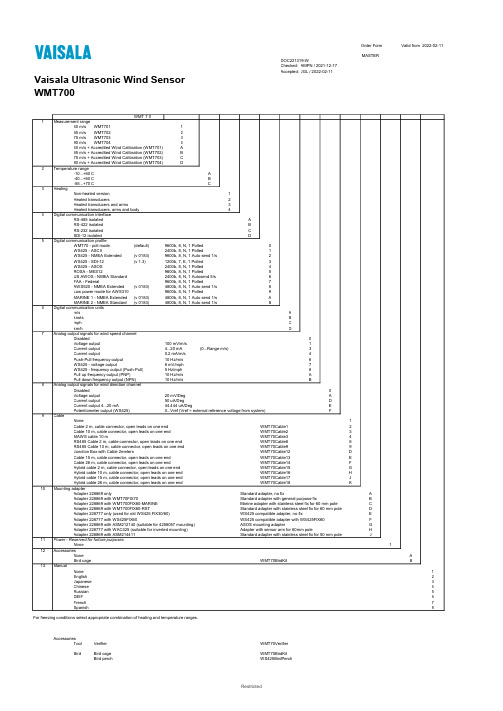
Order Form Valid from2022-02-11MASTERDOC221319-WChecked: AMPN / 2021-12-17Accepted: JGL / 2022-02-11Vaisala Ultrasonic Wind SensorWMT700WMT 7 01Measurement range40 m/s WMT701165 m/s WMT702275 m/s WMT703390 m/s WMT704440 m/s + Accredited Wind Calibration (WMT701)A65 m/s + Accredited Wind Calibration (WMT702)B75 m/s + Accredited Wind Calibration (WMT703)C90 m/s + Accredited Wind Calibration (WMT704)D2Temperature range-10...+60 C A-40...+60 C B-55...+70 C C3HeatingNon-heated version1Heated transducers2Heated transducers and arms3Heated transducers, arms and body44Digital communication interfaceRS-485 isolated ARS-422 isolated BRS-232 isolated CSDI-12 isolated D5Digital communication profileWMT70 - poll mode (default)9600b, 8, N, 1 Polled0WS425 - ASCII 2400b, 8, N, 1 Polled1WS425 - NMEA Extended(v 0183)9600b, 8, N, 1 Auto send 1/s2WS425 - SDI-12 (v 1.3)1200b, 7, E, 1 Polled3WS425 - ASOS 2400b, 8, N, 1 Polled4ROSA - MES12 9600b, 8, N, 1 Polled5US AWOS - NMEA Standard2400b, 8, N, 1 Autosend 5/s6FAA - Federal9600b, 8, N, 1 Polled7AWS520 - NMEA Extended(v 0183)4800b, 8, N, 1 Auto send 1/s8Low power mode for AWS3109600b, 8, N, 1 Polled9MARINE 1 - NMEA Extended(v 0183)4800b, 8, N, 1 Auto send 1/s AMARINE 2 - NMEA Standard(v 0183)4800b, 8, N, 1 Auto send 1/s B6Digital communication unitsm/s Aknots Bmph Ckm/h D7Analog output signals for wind speed channelDisabled0Voltage output100 mV/m/s1Current output 4...20 mA(0...Range m/s)3Current output0.2 mA/m/s4Push-Pull frequency output10 Hz/m/s6WS425 - voltage output8 mV/mph7WS425 - frequency output (Push-Pull) 5 Hz/mph8Pull up frequency output (PNP)10 Hz/m/s APull down frequency output (NPN)10 Hz/m/s B8Analog output signals for wind direction channelDisabled0Voltage output20 mV/Deg ACurrent output50 uA/Deg DCurrent output 4...20 mA44.444 uA/Deg EPotentiometer output (WS425)0...Vref (Vref = external reference voltage from system)F9CableNone1Cable 2 m, cable connector, open leads on one end WMT70Cable12Cable 10 m, cable connector, open leads on one end WMT70Cable23MAWS cable 10 m WMT70Cable34RS485 Cable 2 m, cable connector, open leads on one end WMT70Cable88RS485 Cable 10 m, cable connector, open leads on one end WMT70Cable99Junction Box with Cable 2meters WMT70Cable12DCable 15 m, cable connector, open leads on one end WMT70Cable13ECable 26 m, cable connector, open leads on one end WMT70Cable14FHybrid cable 2 m, cable connector, open leads on one end WMT70Cable15GHybrid cable 10 m, cable connector, open leads on one end WMT70Cable16HHybrid cable 15 m, cable connector, open leads on one end WMT70Cable17JHybrid cable 26 m, cable connector, open leads on one end WMT70Cable18K 10Mounting adapterAdapter 228869 only Standard adapter, no fix AAdapter 228869 with WMT70FIX70Standard adapter with general purpose fix BAdapter 228869 with WMT700FIX60-MARINE Marine adapter with stainless steel fix for 60 mm pole CAdapter 228869 with WMT700FIX60-RST Standard adapter with stainless steel fix for 60 mm pole DAdapter 228777 only (used for old WS425 FIX30/60)WS425 compatible adapter, no fix EAdapter 228777 with WS425FIX60WS425 compatible adapter with WS425FIX60FAdapter 228869 with ASM212140 (suitable for 4258057 mounting)ASOS mounting adapter GAdapter 228777 with WAC425 (suitable for inverted mounting)Adapter with sensor arm for 60mm pole HAdapter 228869 with ASM214411Standard adapter with stainless steel fix for 50 mm pole J 11Power - Reserved for furture purposesNone1 12AccessoriesNone ABird cage WMT70BirdKit B 13ManualNone1English2Japanese3Chinese4Russian5DEIF6French7Spanish8For freezing conditions select appropriate combination of heating and temperature ranges.AccessoriesTool Verifier WMT70VerifierBird Bird cage WMT70BirdKitBird perch WS425BirdPerchCable Cable 2 m, cable connector, open leads on one end227567SP Cable 10 m, cable connector, open leads on one end227568SPCable 15 m, cable connector, open leads on one end237890SPCable 26 m, cable connector, open leads on one end237889SPRS485 Cable 2 m, cable connector, open leads on one end228259SPRS485 Cable 10 m, cable connector, open leads on one end228260SPMAWS cable 10 m227565SPROSA analog cable 10 m, cable connector, open leads on one end231425SPAdapter cable for WS425 serial227569SPAdapter cable for WS425 analog frequency output227570SPJunction Box with Cable 2meters ASM210719SPWMT700 USB service cable240855Universal USB service cable with screw terminal for RS485 or RS232240884Hybrid cable 2 m, cable connector, open leads on one end CBL210706-2MSPHybrid cable 10 m, cable connector, open leads on one end CBL210706-10MSPHybrid cable 15 m, cable connector, open leads on one end CBL210706-15MSPHybrid cable 26 m, cable connector, open leads on one end CBL210706-26MSP Mounting WMT700 Mounting Accessories:Adapter for FIX70228869Fix70 (suitable also for inverted mounting)WMT70FixSPMounting adapter 60mm POM WMT700FIX60-POMSP Mounting adapter 60mm RST WMT700FIX60-RSTSP Cross-arm (40x40x850mm)WMT70CROSSARMMounting adapter between 228869 and 4258057ASM212140Mounting adapter 50mm RST ASM214411WS425 Mounting Accessories:Adapter for old WS425 FIX30/60228777FIX30WS425Fix30FIX60WS425Fix60Sensor support arm for 60mm pole (655mm with integrated fix for item 228777)WAC425Power Outdoor AC (mains) power supply for arm heated and fully heated WMT700PJB480Display Wind display XDi-N 144 (5’’ display) for ship navigation252307 Wind display XDi-N 192 (7’ display) for ship navigation252321。
风速传感器 说明书
一、产品概述 (2)二、应用范围 (2)三、技术参数 (2)四、功能特点 (4)五、结构尺寸图 (4)六、固定方式 (4)七、信号输出定义 (4)八、线色定义 (5)九、脉冲型风速输出电路图 (5)十、脉冲输出型计算 (6)十一、RS485/232通讯协议 (6)十二、风力等级划分表 (10)十三、风速与输出信号对应表 (11)一、产品概述该三杯式风速传感器是我公司自主研发、生产的一款风速测量仪器,本品由壳体、风杯和电路模块组成,内部集成光电转换机构、工业微电脑处理器、标准电流发生器、电流驱动器等。
传感器壳体和风杯采用铝合金材料,使用特种模具精密压铸工艺,尺寸公差甚小表面精度甚高,内部电路均经过防护处理,整个传感器具有很高的强度、耐候性、防腐蚀和防水性。
电缆接插件为军工插头,具有良好的防腐、防侵蚀性能,能够保证仪器长期使用,同时配合使用风速传感器内部进口轴承系统说明书,确保了风速采集的精确性。
电路PCB采用军工级A级材料,确保了参数的稳定和电气性能的品质;电子元件均采用进口工业级芯片,使得整体具有极可靠的抗电磁干扰能力,能保证主机在-20℃~+50℃,湿度35%~85%(不结露)范围内均能正常工作。
二、应用范围本产品可广泛运用于工程机械(起重机、履带吊、门吊、塔吊等)领域,铁路、港口、码头、电厂、气象、索道、环境、温室、养殖、空气调节、节能监控、农业、医疗、洁净空间等领域风速的测量,并输出相应的信号。
三、技术参数□脉冲输出型:□ NPN输出□ PNP输出□ NPN输出带内部上拉(4.7KΩ)□RS485通讯型□电压输出型:□ 0-2VDC □ 0-5VDC □ 0-10VDC □电流输出型: 4-20mA电源:根据输出类型不同所需的电压源范围不同电流输出型: 12~24V电压输出型:输出0-2VDC:6~24V输出0-5VDC:6~24V输出0-10VDC:12~24V脉冲输出型:5~24V量程:□0-30m/s □0-60m/s负载能力: □其他□<500Ω□>2kΩ最大功耗(DC24V): 脉冲型MAX≤200mW;电压型MAX≤300mW;电流型MAX≤700mW;启动风力:0.4~0.8m/s 重量:≤0.5Kg四、功能特点该产品自投入市场以来,以其优异的质量,卓越的性能赢得广大用户的好评,具备以下特点:◆外观结构设计合理、美观大方,体积小,便于携带,安装简便。
- 1、下载文档前请自行甄别文档内容的完整性,平台不提供额外的编辑、内容补充、找答案等附加服务。
- 2、"仅部分预览"的文档,不可在线预览部分如存在完整性等问题,可反馈申请退款(可完整预览的文档不适用该条件!)。
- 3、如文档侵犯您的权益,请联系客服反馈,我们会尽快为您处理(人工客服工作时间:9:00-18:30)。
风速传感器说明书文件编码(008-TTIG-UTITD-GKBTT-PUUTI-WYTUI-8256)
一、产品概述
该三杯式风速传感器是我公司自主研发、生产的一款风速测量仪器,本品由壳体、风杯和电路模块组成,内部集成光电转换机构、工业微电脑处理器、标准电流发生器、电流驱动器等。
传感器壳体和风杯采用铝合金材料,使用特种模具精密压铸工艺,尺寸公差甚小表面精度甚高,内部电路均经过防护处理,整个传感器具有很高的强度、耐候性、防腐蚀和防水性。
电缆接插件为军工插头,具有良好的防腐、防侵蚀性能,能够保证仪器长期使用,同时配合使用风速传感器内部进口轴承系统说明书,确保了风速采集的精确性。
电路PCB采用军工级A级材料,确保了参数的稳定和电气性能的品质;电子元件均采用进口工业级芯片,使得整体具有极可靠的抗电磁干扰能力,能保证主机在-20℃~+50℃,湿度35%~85%(不结露)范围内均能正常工作。
二、应用范围
本产品可广泛运用于工程机械(起重机、履带吊、门吊、塔吊等)领域,铁路、港口、码头、电厂、气象、索道、环境、温室、养殖、空气调节、节能监控、农业、医疗、洁净空间等领域风速的测量,并输出相应的信号。
三、技术参数
□脉冲输出型:□ NPN输出□ PNP输出
□ NPN输出带内部上拉(Ω)
□RS485通讯型
□电压输出型:□ 0-2VDC □ 0-5VDC □ 0-10VDC □电流输出型: 4-20mA
电源:根据输出类型不同所需的电压源范围不同电流输出型: 12~24V
电压输出型:输出0-2VDC:6~24V
输出0-5VDC:6~24V
输出0-10VDC:12~24V
脉冲输出型:5~24V
量程:□0-30m/s □0-60m/s
负载能力: □其他□<500Ω□>2kΩ
最大功耗(DC24V): 脉冲型MAX≤200mW;
电压型MAX≤300mW;
电流型MAX≤700mW;
启动风力:~s 重量:≤
四、功能特点
该产品自投入市场以来,以其优异的质量,卓越的性能赢得广大用户的好评,具备以下特点:
◆外观结构设计合理、美观大方,体积小,便于携带,安装简便。
◆测量精度高,量程范围宽,稳定性好。
◆有较强的防腐蚀性和耐候性。
◆动态特性好,抗外界干扰能力强,测量精度高。
◆功耗低,电路寿命长,能长期稳定工作;
◆电源适应范围宽,数据信息线性度好,信号传输距离长。
五、结构尺寸图
六、固定方式
传感器应水平安装,确保风向数据的准确性;采用法兰安装方式,传感器下方安装法兰直径Ф60mm,四个安装孔为Ф,四个安装孔均匀分布再Ф47mm的圆周上,安装使用法兰固定安装,安装尺寸如下:
七、信号输出定义
电压型和电流型输出定义如下
RS485输出定义
八、线色定义
线型常用颜色备用颜色
电源线色红色
地线线色黑色
信号线色蓝色--------A+
黄色---------B-
九、脉冲型风速输出电路图
PNP输出电路图如下:(最大输出电流Icmax=100mA)
当用电压信号时,
需要连接电阻R
L
NPN输出电路图如下:(最大灌电流
Icmax=20mA)
当用电压信号时,
需要连接电阻R
L
内部带上拉电阻NPN输出电路图如下:(R=Ω)
十、脉冲输出型计算
风速=单位时间内的脉冲数X系数;
公式中:单位时
间内指的是1S;
型号尾缀为4CM,则系数为
型号尾缀为8CM,则系数为
型号尾缀为12CM,则系数为
型号尾缀为16CM,则系数为
十一、RS485/232通讯协议
采用了MODBUS-RTU协议的命令子集,使用读寄存器命令(03)(06)。
1、数据传输方式:
8位数据位,1位停止位,无校验位。
2、数据传输速率:
缺省波特率为9600bps,不可修改,用户希望使用其他波特率时,请在定货时声明。
支持波特率:9600bps,4800bps,2400bps,1200bps。
3、数据报文格式
⑴功能码0x03---查询从设备寄存器内容
⑵功能码0x06---对从设备寄存器置数
注:1、CRC检验码低位在前、高位在后,寄存器地址, 寄存器个数,数据均为高位在前、低位在后; 2、寄存器字长为16bit(两个字节);
4、寄存器说明与命令格式
(1)参量数据寄存器定义表
提示:自2013年12月20日起所有485风速传感器风速值寄存器地址全部修改为0x002A,老客户使用过的风速值寄存器地址0x0010、0x0002、0x0000,修改后的协议仍然支持上述地址,客户无需做修改。
数据范围0x0000-0x0BB8代表米/秒风速。
(2)命令举例:
命令中所有寄存器地址字节、寄存器个数字节、数据字节高位在前,低位在后;CRC校验码低位字节在前,高位字节在后;
读取风速值:
(从设备地址02号,波特率为9600,N,8,1)
从设备回应:
修改设备地址:
(从设备地址02号,修改为03号)
从设备回应:
十二、风力等级划分表
十三、风速与输出信号对应表
风速(m/s)电流输出4-
20mA
电压输出
(0-5V)
电压输出
(1-5V)
电压输出(0-
2V)
1
2
3
4
5
61
7
8
9
10
11
122
13
14
151231
16
17
183
19
20
21
22
23
244
25
26
27
28
29
3020552十四、维护和保养
本仪器属精密的电子产品,正确的的维护和保养有助于保护仪器性能、延长仪器的使用寿命,请注意以下几点:
1、请依据使用说明书的要求正确使用说明书,接钱有误有可能导致仪器
损坏。
2、不要用挥发性液体擦拭仪器,否则可能导致仪器变色变形;软布擦
拭,避免仪器外部保护膜划伤,延长仪器使用寿命。
3、仪器应轻拿轻放,不得摔落或重压,否则将导致仪器变形、内部电路
板损坏。
4、不要在仪器带电的情况下触摸感应部位,以影响量结果或导致仪器内
部电路的损坏。
5、请勿私自拆卸和改装本仪器,以免对仪器造成损坏。
6、仪器使用时应用螺丝牢固固定,否则有可能损坏仪器。
7、定期检查仪器电源电压,确保仪器正常运行。