显微镜12.09
莱卡 DM2700 M 光学显微镜使用手册说明书

From Eye to InsightLeica DM2700 MThe reliable and convenient upright materials microscope with bright universal LED illumination.3 LEIca DM2700 M – ThE rELIabLE, convEnIEnT uprIghT MaTErIaLs MIcroscopESimple and Reliable:The Leica DM2700 MSee materials in the best lightExamine materials in the best light. The universal white light (4500 K) LED illumination in combination with renowned high quality Leica optics provide the ideal inspection tool for all of your quality assessments. The Leica DM2700 M demonstrates how simple and reliable microscopy can be, while at the same time, helps to improve your workflow so you can concentrate on the task at hand.›Brilliance›Reliability›Flexibility›Easy Documentation4LeD illumination, Daylight at a Touch The universal microscope illumination for a wide range of industrial applicationsA powerful light source for Brightfield, Darkfield, Differential Contrast, and Polarized Images on the right: Universal LED illumination.Light applications:› white light, constant color temperature› true color imaging› entirely adjustment-free› and lasts 20 yearsEnter the future of microscopy.5LEIca DM2700 M – ThE rELIabLE, convEnIEnT uprIghT MaTErIaLs MIcroscopE image Brilliance You can count OnTop of the line opticsA microscope is as good as its optics. This statement is still true for in today's digital Image on the right: n PLAn EPI series of objectives (plan achromat)world. The brand Leica Microsystems has always represented the highest standards in optical performance. Leica objectives are innovative, cost-effective, and always pro-vide high-contrast, pin sharp images as seen through the eyepieces and captured with digital cameras. They combine brilliance and sharp contrast with high resolution and optimized image fields. Whatever your work demands Leica Microsystems offers anaffordable solution.6Reliability You can count OnWe don’t make a science out of microscope operationUncomplicated AnD easy to understand functionality is built into the design of theLeica DM2700 M. Concentrate on your work, not on microscope adjustments.Ferrit C60, etched, undereutectoid, ferrit-perlite grain structure. LED brightfield, 500xBEnEFITSThe combination of Leica's color codedobjectives and the aperture diaphragmresults in the Color Coded DiaphragmAssistant (CCDA). With it, the basicsetting of resolution, contrast, and depth of field is simple and straightforward.The built-in focus stop, the heightadjustable focus knobs, as well as the three-gear focus mechanism for coarse, fine, and ultra-fine focusing make the Leica DM2700 M convenient and reliable for daily use. It can dramatically speed up your work processes while minimizingoperating errors. Using a manual microscope has never been easier.Accept no compromises when it comes to operation, performance, and features. The Leica DM2700 M is sturdy, durable, and ergonomically designed for ease ofuse and user comfort.7LEIca DM2700 M– ThE rELIabLE, convEnIEnT uprIghT MaTErIaLs MIcroscopE Flexibility Means Saving MoneyVersatility for all samplesThe Leica DM2700 M is a flexible upright microscope system for Brightfield (BF),Darkfield (DF), DIfferential Interference Contrast (DIC), Qualitative Polarization (PoL), and Fluorescence (FLUo) applications. In addition to all incident light applications, theLeica DM2700 M can also be equipped with transmitted light.Image on the right: Leica DM2700 M with Ergo Tube, upright/non-reversed image, 100%-0%, 50%-50%, 0%-100% beamsplitter.oBJECTIVE TURRETS There are three objective turrets tochoose from: The BF/DF M32 nosepieceholds up to five objectives, while the (BF/FLUo) can accommodate six or seven objectives.FLExIBLE In EVERY APPLICATIon Specimens with a size of up to 100 × 100 mm – such as foils, wafers or PCBs – and a thickness of up to 80 mm, such asmachined components, can be examined using the comprehensive stage program.KEEP TRACK oF YoUR SAMPLESThe Macro objective enables you to see almost 40 mm of the sample at a glance. The ideal addition for fast orientation and overview documentation.8Documentation SimplifiedDocumenting, saving, and retrieving imagesLeica digital cameras, optimized for reflected light applications, in combinationwith Leica Application Suite (LAS) image acquisition and archiving software, ensureconvenient and efficient documentation of your results.Upper image: Coated and annealed brass sample in LED brightfield-oblique contrast, 500x,Lower image: Plastic composite material in LED brightfield-oblique contrast, 200x. 3D-like image due to oblique illumination.QUICK AnD PRECISE AnALYSIS oF MATERIALS DATALeica Steel Expert, Phase & grain Expert, and Cleanliness Expert are dedicatedsoftware packages that providehigh-quality solutions, particularly in environments that require high samplethroughput and automated operation. With a modular structure, the functional-ity ranges from simple, interactive to automated photogrammetry; for example, characterizing metal surfaces or particle analysis.9 Chapter – SubChapter10(Dimensions in mm)Dimensions Leica DM2700 M331.4410505.5302.8365.8Undereutectoid, ferrit-perlite grain structure LED brightfield-oblique contrast, n Plan 100x Undereutectoid, ferrit-perlite grain structure LED brightfield contrast, n Plan 100xLEIca DM2700 M – ThE rELIabLE, convEnIEnT uprIghT MaTErIaLs MIcroscopE11 SpecificationsLeica DM2700 Morder no.: English 11914788 ∙ Copyright © by Leica Microsystems CMS gmbh,Wetzlar, germany, 2016. Subject to modifications. LEICA and the Leica Logo are registered trademarks of Leica Microsystems IR gmbh.Leica Microsystems – an international company with a strong network of worldwide customer services:Leica Microsystems operates globally in three divisions, where we rank with the market leaders.LIFE SCIEnCE DIVISIonThe Leica Microsystems Life Science Division supports the imaging needs of the scientific community with advanced innovation and technical expertise for the visualization, measurement, and analysis of microstructures. our strong focus on understanding scientific applications puts Leica Microsystems’ customers at the leading edge of science.InDUSTRY DIVISIonThe Leica Microsystems Industry Division’s focus is to supportc ustomers’ pursuit of the highest quality end result. Leica Microsystems provide the best and most innovative imaging systems to see, measure, and analyze the microstructures in routine and research industrial applications, materials science, quality control, forensic science inves-tigation, and educational applications.MEDICAL DIVISIonThe Leica Microsystems Medical Division’s focus is to partner with and support surgeons and their care of patients with the highest-quality, most innovative surgical microscope technology today and into the future.The statement by Ernst Leitz in 1907, “With the User, For the User,” describes the fruitful collaboration with end users and driving force of innovation at Leica Microsystems. We have developed five brand values to live up to this tradition: Pioneering, high-end Quality, Team Spirit, Dedication to Science, and Continuous Improvement. For us, living up to these values means: Living up to Life .active worldwide Tel. Fax australia ∙ north ryde+61 2 8870 3500 2 9878 1055austria ∙ vienna +43 1 486 80 50 0 1 486 80 50 30belgium ∙ Diegem +32 2 790 98 50 2 790 98 68canada ∙ concord/ontario +1 800 248 0123 847 405 0164Denmark ∙ ballerup +45 4454 0101 4454 0111France ∙ nanterre cedex+33 811 000 664 1 56 05 23 23germany ∙ Wetzlar +49 64 41 29 40 00 64 41 29 41 55Italy ∙ Milan +39 02 574 861 02 574 03392Japan ∙ Tokyo +81 3 5421 2800 3 5421 2896Korea ∙ seoul+82 2 514 65 43 2 514 65 48netherlands ∙ rijswijk+31 70 4132 100 70 4132 109people’s rep. of china ∙ hong Kong +852 2564 6699 2564 4163∙ shanghai +86 21 6387 6606 21 6387 6698portugal ∙ Lisbon +351 21 388 9112 21 385 4668singapore +65 6779 7823 6773 0628spain ∙ barcelona +34 93 494 95 30 93 494 95 32sweden ∙ Kista+46 8 625 45 45 8 625 45 10switzerland ∙ heerbrugg +41 71 726 34 34 71 726 34 44united Kingdom ∙ Milton Keynes +44 800 298 2344 1908 246312usa ∙ buffalo grove/lllinois+1800 248 0123847 405 0164。
ZEISS KINEVO 900 高精度手术显微镜说明书
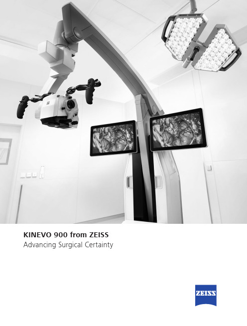
Advancing Surgical CertaintyKINEVO 900 – The Robotic Visualization System Just like you, we love challenging the status quo.The result? Over 100 innovations to perfect the already acclaimed surgical visualization platform. KINEVO® 900 from ZEISS is designedto deliver more functionalities than any surgical microscope today.ZEISS KINEVO 900 combines digital and optical visualization modalities, offers a unique Micro-Inspection Tool and will impress you with its Surgeon-Controlled Robotics. All to enable you to gain greater certainty in a virtually disruption-free workflow.Designed to meet real needs. To make a real difference!A lot more. And, a lot less too.When treating complex vascular conditions, you typically work at high magnification. Even the slightest vibrations can cause disruptions. And constant manual repositioning to better visualize structures or precisely approach deep-seated lesions can become extremely tedious. Not anymore! ZEISS KINEVO 900 delivers a lot more positioning precision with a lot less effort.PointLockSurgeon-Controlled Robotics adds a complete new level of ease to precise positioning. Imagine being able to focus and move around a structure to visualize the targeted anatomy – reducing any manual hassle. In addition, PointLock enables you to do a KeyHole movement to observe a larger area inside a cavity – a particular benefit in areas with narrow access. Simply put:Focus. Activate. Swivel.Active vibration dampingYou know the problems that can be created by the tiniest vibrations. The active damping provided by ZEISS KINEVO 900 minimizes collateral system vibrations, ensuring rock-solid stability. Enabling you to completely, and steadily, focus on what matters most:your treatment.Focus Activate Swivel5When you need it. Where you need it.The new navigation interface of ZEISS KINEVO 900 is designed to work in concert with your navigation device. When you require precise repositioning to reexamine previously visualized structures or when you need to align with a pre-mapped trajectory, making use of all six axes, the Robotic Visualization System ® delivers precise positioning at the push of a button. Putting you exactly where you need to be – when you need to be there.PositionMemoryWhen working on a tumor case, you may already have identified regions of concern where you want to protect the functional structure. After storing these in PositionMemory , you can come back and visualize them at the exact same magnification, working distance and focus – without losing time for manual repositioning. In a nutshell: Save. Move. Recall.Image-guided surgeryMinimize time-consuming efforts in approaching challenging neurosurgicalpathologies. Combine the Surgeon-Controlled Robotics of ZEISS KINEVO 900 with navigation interface to approach deep-seated pathologies in cranial surgery, brain stem or skull base tumor removals –right when you need it.Save Move RecallImage with Brainlab Microscope Navigation Software7New dimensions. Freedom of choice. Working through oculars at extreme angles can sometimes be a pain in the neck. Literally. With no way out, you might have to contend with uncomfortable working positions causing fatigue. Now, relief and revolutionary dimensions in visualization arein sight.The Digital Hybrid Visualization with integrated 4K technology of ZEISS KINEVO 900 welcomes you to a world of heads-up ocular-free surgery, giving you freedom of movement. And freedom of choice to use an optical setup, depending on the application need.Fully integrated 4K camera technologyDuring lateral lumbar or thoracic spine and posterior fossa approaches,ZEISS KINEVO 900’s integrated 4K visualization can be essential. It providesyou with multimodal visualization capabilities – the flexibility to decouple fromthe classic optical approach and to work with outstanding 4K picture qualityand clarity. Even when magnifying tiny details.What’s more… your assistant surgeon, OR staff and residents also benefit from the 4K visual clarity of ZEISS KINEVO 900. They share the same high-resolution, digital image to follow the procedure with comparable fidelity. Delivering indispensable education and training.9Critical challenge. Vital solution.Your challenge: When working from an external perspectiveof a surgical microscope, your visualization of the anatomy is limited to a straight line of sight – missing critical information behind tissue or corners. Efficient and effortless access to this comprehensive information is essential for treatment.Our solution: QEVO® from ZEISSThe unique, proprietary Micro-Inspection Tool from ZEISS complements intraoperative microsurgical visualization, enabling you to discover unexplored areas during the surgical intervention without additional footprint. You can look around corners and eliminate blind spots. And most importantly, you can gain greater insights – for better clinical decisions.To support your surgical workflow, ZEISS QEVO is engineered with an angled design – keeping your hands out of the lineof sight during insertion in the surgical field. And, it allowsfor an easy fit between the ZEISS KINEVO 900 and the situs, eliminating the need to reposition the head of the device. Greater insights, on demand.ZEISS QEVO enables you to inspect the perforator or examine the distal neck of the aneurysm to ensure the clip blades are fully extended.11Ease of use. Peace of mind.Surgical certainty is your imperative. Enabling you to achieve it is ours. That’s why, in the development of the Micro-Inspection Tool, we placed a high priority on its ease of use.ZEISS QEVO is truly integrated. You don’t have to plan foran additional device during surgery. Just plug it into your ZEISS KINEVO 900 for a seamless surgical workflow and to easily switch back and forth between views.ZEISS QEVO is fully autoclavable.So there’s no need forany additional draping. This is another attribute that makes ZEISS QEVO an indispensable tool – always available during surgery. On demand.ZEISS QEVO. Innovation in action.ZEISS KINEVO 900 can support discerning regions that are not directly visualized – avoiding unnecessary bone removal and retraction. During a Vestibular Schwannoma case, for instance, it can help identify the course of facial nerves. And, can support inspection of regions that are not directly visualized by a surgical microscope.1314For the fluorescence distribution: The IntensityMap enables you to conveniently identify relativefluorescence levels reached during the INFRARED800 observation period.For the speed of the flow: The Speed Mapindicates how fast the fluorescence intensityincreased during the observation period –indicating the speed of the blood flow.For the indicative time: The Delay Map (orSummary Map) provides quick information aboutthe time when the fluorescent signal appeared foreach image point in the map.1PZEISS BLUE 4001ZEISS YELLOW 5601Visualization of fluorescence-stained structures using BLUE 400 during surgery.Visualization of fluorescence-stained structures using YELLOW 560.For a complete picture: The Diagram Functionoutlines assessment of fluorescence intensityvariation over time and fast access to the keyindicators for further analysis.BeforeFor no compromises:After15Setting new benchmarks. Shaping a new future. When we envisioned the all-new Robotic Visualization System,we conceived a design that can deliver so much more withoutlosing its familiarity. With ZEISS KINEVO 900, we continue tolive our vision of supporting you in becoming one with yourvisualization system – of delivering purposeful innovations.ones that matter the most for you.The Robotic Visualization System: The first of its kind.Surgeon-Controlled RoboticsDelivering precise positioning with a lotless effort – with motors in all axes.ZEISS QEVO – The Micro-Inspection ToolComplementing intraoperative microsurgicalvisualization to discover unexplored areasduring surgical intervention. Gain greaterinsight. On demand.16Digital Hybrid VisualizationProviding an opportunity for ocular-free surgery, with the freedom to use a traditional optical setup – depending on the application need.Integrated Intraoperative Fluorescence –The Power of Four.The redesigned intraoperative fluorescence technologies from ZEISS offer you the Power of Four – so you always have the tools you need.17Digital connectivity. Transforming OR’s.ZEISS ConnectZEISS Observe Neurosurgery, in particular, is a technologically intensivesurgical discipline. This has pushed us toward the edge oftransformation: to develop leading digital technologiesenabling you to expand the boundaries of surgical care –to the next level.ZEISS KINEVO 900 offers full digital connectivity.Manage surgical data wherever you are: ZEISS Connect App1enables you to access your surgical data from your iOS device,and also delivers dedicated functionalities for efficient work-flows.Take teaching to new heights: ZEISS Observe App enablesyou to virtually broadcast your procedure in the OR. Yourstudents can follow the live surgery directly on mobile screensor immerse themselves in a rich VR Experience.Gain value with new digital services: ZEISS Smart Servicesenables faster support for you and your team with remoteconnectivity. Benefit from the increased system availabilitypowered by a secure connection to your ZEISS KINEVO 900.1 Available soon18Connecting simplicity and innovation.ZEISS SMARTDRAPEYour visualization needs are paramount to us. And, soare the needs of your team. That’s why we gave a specialfocus to the OR preparation process in the developmentof ZEISS KINEVO 900.Being an integral part of the optical path, the SMARTDRAPEwith VisionGuard® from ZEISS is designed together withZEISS KINEVO 900 so you and your team can have thebenefits of a vivid view, and effective patient protection.At the same time – the new innovations make the drapingprocess simply simple!• Innovative folding: to eliminate guesswork and complexity.• Intuitive attachment: for an effortless and simple self-locking mechanism.• Integrated RFID chip: for easy activation of AutoDrape®.Designed for ZEISS KINEVO 900.Support whenever you need it.ZEISS OPTIMEIf you rely on high system availability, consider our ZEISSOPTIME service agreements, which are designed to ensurethe readiness of our medical equipment when you need it.ZEISS OPTIME service agreements for ZEISS KINEVO 900now come with connectivity for ZEISS Smart Services.19Technical DataKINEVO ® 900 from ZEISS5°A x i s 6-25° / +135°A x i s 4±45°A x i s 5-28° / +20°A x i s 3n x 360°A x i s 1M o n i t o r R o t a t i o n : ±125°T i l t i n g : -20° / +5° (±3°)c a . 530 - 1635 m m820 m mm a x . c a .1760m m Technical DataRated Voltage 100 V – 240 VCurrent Consumption Max. 1.350 VARated Frequency 50 Hz – 60 HzElectrical Standard Complying with IEC 60601 1:2005+A1:2012Protection class I, degree of protection IP20Class 2 laser product as perapprox. 525 kg20QEVO® from ZEISS and QEVO ECUTechnical DataDirection of View45° upwardsShaft Diameter 3.6 mmShaft Length120.0 ± 1.0 mmTotal Diameter13.0 mmField of View 100° ± 5° wide angle viewIllumination20 – 35 lumen LEDWeight (without cable)250 gSterilization AutoclavableImage Resolution1920 x 1080 pixel full HDLength of Cable5000 mmOperation Temperature+10 to +40 °C (500/1000 s intermittent use)QEVO ECUDimensions Length = 265.0 ± 1 mm, height = 59.3 ±1 mm and depth = 212.2 ± 1 mmWeight 2.5 kgOperating Voltage24V (+/- 10%) ADCVideo Output DVI-D full HDCable length: 5 m21Technical DataVideoStereo video camera 3D HD, fully integrated, 2 x 3-chip HD, 1080p incl. 2nd HD 3D monitor 4K video camera, fully integrated 3-chip 4K, 2160p Stereo video camera 4K 3D, fully integrated, 2 x 3-chip 4K, 2160p, incl. 2nd HD 3D monitor Integrated HD video recording, withSmartRecording, low-Resolution recording, editing and streaming 2nd system monitor HD 2DAttachment for consumer (SLR) photo camera External 55" 4K 3D video monitor, with mobile cartIntraoperative FluorescenceBLUE 400INFRARED 800INFRARED 800 Compact INFRARED 800 with FLOW 800YELLOW 560Connectivity / Data Manage- mentDICOM module for image and video data transfer from / to PACS. Patient management by modality worklist management.Shared Network Data storage WLAN option, with WiFi Hotspot Navigation Interface Standard Navigation Interface ExtendedAccessories ZEISS QEVO and QEVO ECU12.5x magnetic wide field eyepieces with integrated eyecups Stereo co-observation tubeFoldable Tube f170 / f260, including the PROMAG function for additional 50 % magnification and integrated rotate functionTiltable binocular tube, swivel range 180°, focal length f = 170 mm14-function, wired foot control panel 14-function, wireless foot control panel 2-function foot switch Mouth switch3-step magnification changerApochromatic Optics Motorized focus; Varioskop ® with working distance 200 – 625 mmMotorized zoom; zoom ratio 1:6, magnification factor y = 0.4x – 2.4x10x magnetic wide field eyepieces with integrated eyecupsAutoFokus with 2 visible laser dots, automatic mode with magnetic brakesIllumination 2 x 300 W Xenon, with automatic lamp exchange Automatic Iris Control for adjusting the illumination to the field of view Individual light threshold settingFocus Light Link: working distance controlled light intensityManual adjustment of diameter of field of illuminationAdditional illumination beam to brighten up shadows, motorizedSystem OperationMultifunctional programmable handgrips Magnetic clutches for all system axes Central user interface with full-screen video XY robotic movement in 6 axes (variable speed)Active dampingManual and motorized PointLock function with variable speed PositionMemoryMotorized XY lateral movement with variable speedMultiVision System (HD), with shutter controlSystem Setup AutoBalanceAutoDrape – air evacuation system 1Park Position Drape PositionVideo Integrated 3-chip Full HD video camera, 1080p 24" HD video touchscreen on extendable arm, 16:9 aspect ratioIntegrated still image capturing both on HDD and USB-mediaConnectivity / Data Manage- ment Video-in for external HD video sources Remote diagnosis via internet / VPN Sterile DrapeZEISS SMARTDRAPE1Available with ZEISS SMARTDRAPE only.22Your needs. Our packages.Select a ZEISS KINEVO 900 built to fit your typical clinical use-cases. ZEISS KINEVO 900 comes with pre-defined packages giving you a head start in planning the most suitable configuration for your specific needs.Interested in digital visualization? Check out the digital package. That’s our commitment to cover you for tomorrow while keeping your present needs into focus.always included always included as INFRARED 800 only optional23S U R . 8733 R e v E P r i n t e d i n t h e U n i t e d S t a t e s . C Z -I V /2019 U n i t e d S t a t e s E d i t i o n . O n l y f o r s a l e i n s e l e c t e d c o u n t r i e s .T h e c o n t e n t s o f t h e b r o c h u r e m a y d i f f e r f r o m t h e c u r r e n t s t a t u s o f a p p r o v a l o f t h e p r o d u c t o r s e r v i c e o f f e r i n g i n y o u r c o u n t r y . P l e a s e c o n t a c t o u r r e g i o n a l r e p r e s e n t a t i v e s f o r m o r e i n f o r m a t i o n . S u b j e c t t o c h a n g e s i n d e s i g n a n d s c o p e o f d e l i v e r y a n d d u e t o o n g o i n g t e c h n i c a l d e v e l o p m e n t . R o b o t i c V i s u a l i z a t i o n S y s t e m , K I N E V O , Q E V O , F L O W , A u t o D r a p e , V a r i o s k o p a n d V i s i o n G u a r d a r e e i t h e r t r a d e m a r k s o r r e g i s t e r e d t r a d e m a r k s o f C a r l Z e i s s M e d i t e c A G .© C a r l Z e i s s M e d i t e c A G , 2019. A l l r i g h t s r e s e r v e d .View of the cerebellar tonsils and medulla. Image courtesy of Dr. Robert F. Spetzler, Barrow Neurological Institute, Phoenix, Arizona, USA. (Cover page)View onto cerebellum and lower cranial nerves. Image courtesy of Dr. Robert F. Spetzler, Barrow Neurological Institute, Phoenix, Arizona, USA. (Page 2) Front temporal area for STA-MCA bypass procedure. Image courtesy of Dr. Peter Nakaji, Barrow Neurological Institute, Phoenix, Arizona, USA (Page 2)View onto optic nerve and internal carotid artery. Image courtesy of Dr. Peter Nakaji, Barrow Neurological Institute, Phoenix, Arizona, USA (Page 4)Image-guided surgery. Image courtesy of BrainLab AG (Page 6 and 7)View onto spinal cord dura. Image courtesy of Dr. Robert F. Spetzler, Barrow Neurological Institute, Phoenix, Arizona, USA (Page 8 and 9)Small view of the cerebellum through the Retrosigmoid Approach. Image courtesy of Dr. Peter Nakaji, Barrow Neurological Institute, Phoenix, Arizona, USA (Page 10)Left mini-pterional approach for clipping an aneurysm. Image courtesy of Dr. Peter Nakaji, Barrow Neurological Institute, Phoenix, Arizona, USA (page 11)View onto corpus callosum and septum pellucidum. Image courtesy of Dr. Peter Nakaji, Barrow Neurological Institute, Phoenix, Arizona, USA (Page 12)Transnasal transspenoidal for re-exploration and excision of recurrent pituitary Macroadenoma with possible abdominal fat. Image courtesy of Dr. William White, Barrow Neurological Institute, Phoenix, Arizona, USA (Page 13)Right temporal Craniotomy for AVM. Image courtesy of Dr. Robert F. Spetzler, Barrow Neurological Institute, Phoenix, Arizona, USA (Page 14 and 15)Glioma surgery using BLUE 400. Image courtesy of Prof. Dr. Walter Stummer, University Clinic, Münster, Germany (Page 15)Left-temporal craniotomy for tumor resection with YELLOW 560. Image Courtesy of Dr. Peter Nakaji, Barrow Neurological Institute, Phoenix, Arizona, USA. (Page 15)Carl Zeiss Meditec AG Goeschwitzer Strasse 51–52 07745 Jena Germany/med /kinevoCarl Zeiss Meditec, Inc.5160 Hacienda Drive Dublin, CA 94568USA/med/us。
人教版高中物理选修3-5第十八章 原子结构(自主学习学案)

第十八章原子结构课前自主学习(学案)一、请学生自主复习教材第十八章原子结构P46至P63。
二、结合复习的内容思考如下问题:1、人类对原子结构认识的历史是从电子的发现开始的。
1890年英国物理学家汤姆孙研究阴极射线发现了电子。
在研究原子结构时,他提出了枣糕模型,请说出这种模型的特点。
2、1909年--1911年,英国物理学家卢瑟福和他的助手做α粒子轰击金箔的实验,即著名的“α粒子散射实验”,该实验的结果是什么?(注意几个关键词)3、请绘制一幅简图,描绘原子核式结构模型的α粒子散射的图景。
4、原子核式结构模型与经典电磁理论的矛盾主要体现在哪两个方面?1913年丹麦的物理学家玻尔提出了原子结构的三个基本假设,建立了玻尔原子模型,请说出玻尔原子模型的三个基本假设的内容。
5、请用玻尔理论解释:为什么原子的发射光谱都是一些分立的亮线?如果大量氢原子处在n=4能级,可辐射出几种频率的光?其中波长最短的光是在哪两个能级之间跃迁时发出的?三、自主解答几道题目:1、卢瑟福原子核式结构理论的主要内容有()A.原子的中心有个核,叫原子核B.原子的正电荷均匀分布在整个原子中C.原子的全部正电荷和几乎全部质量都集中在原子核里D.带负电的电子在核外绕着核旋转2、α粒子散射实验中,不考虑电子和α粒子的碰撞影响,是因为()A.α粒子与电子根本无相互作用B.α粒子受电子作用的合力为零,是因为电子是均匀分布的C.α粒子和电子碰撞损失能量极少,可忽略不计D.电子很小,α粒子碰撞不到电子3、卢瑟福通过_______________实验,发现了原子中间有一个很小的核,并由此提出了原子的核式结构模型,平面示意图中的四条线表示α粒子运动的可能轨迹,在图中完成中间两条α粒子的运动轨迹.4.一个氢原子中的电子从一半径为r a的轨道自发地直接跃迁至另一半径为r b的轨道,已知r a>r b,则在此过程中()A.原子发出一系列频率的光子B.原子要吸收一系列频率的光子C.原子要吸收某一频率的光子D.原子要辐射某一频率的光子参考答案:1.ACD 2.C 3 .4.D课堂主体参与(教案)【学习目标】1、知道并理解原子核式结构模型,了解科学家探究原子结构的过程2、知道原子的能级的概念,并能进行一些简单的应用【重点、难点】1、核式结构模型对α粒子散射实验的解释2、玻尔的原子模型【学习内容】一、课前自主学习检查1、原子结构的认识过程是非常曲折的,请回答核式结构和玻尔模型提出的背景分别是:①___________________________________________________________②___________________________________________________________2、如图所示为卢瑟福和他的同事们做α粒子散射实验的装置示意图,荧光屏和显微镜分别放在图中的A、B、C、D四个位置时,下述对观察到现象的说法中正确的是()A.放在A位置时,相同时间内观察到屏上的闪光次数最多B.放在B位置时,相同时间内观察到屏上的闪光次数只比A位置时稍少些C.放在C、D位置时,屏上观察不到闪光D.放在D位置时,屏上仍能观察到一些闪光,但次数极少3、氢原子的能级和电子可能轨道半径公式分别是:①氢原子的能级公式E n=________E1(其中E1为基态能量,E1=-13.6eV)②氢原子的电子轨道半径公式: r n= ________r1(其中r1内基态半径,r1=0.53×10⁻¹⁰m)4.氢原子的能级图,如图:(1)能级图中的横线表示_____________________(2)横线左端的数字“1,2,3…”表示__________,右端的数字“一13.6,一3.4,…”表示__________________.(3)相邻横线间的距离,表示相邻的能级差,量子数越大,相邻的能级差越_________. (4)带箭头的竖线表示原子由较高能级向较低能级跃迁,原子跃迁条件为:_____________. 5.根据玻尔理论,某原子的电子从能量为E 的轨道跃迁到能量为E ’的轨道,辐射出波长为γ的光,以h 表示普朗克常量,c 表示真空中的光速,求能量E ’. 参考答案:1.①汤姆孙的“枣糕模型”无法解释α粒子散射实验②卢瑟福的核式结构无法解释原子的稳定性和原子光谱的分立特性 2.AD 3.21n ;n 4.氢原子可能的能量状态——定态;量子数;氢原子的能级;小;h γ=E m -E n5.解析:根据玻尔理论,原子从一种定态(设能量为E)跃迁到另一种定态(设能量为E ’)时,它辐射(或吸收)一定频率的光子,光子的能量由这两种定态的能量差决定,即 h γ=E -E ’,又光在真空中传播时λcv =,联立得E'=E 一λch二、构建知识框架,剖析典型概念1.人类对原子结构的认识史是从电子的发现开始的。
OLS5100 激光显微镜使用手册说明书

3D测量激光显微镜OLS5100更智能的工作流程,更快速的实验设计实现高效实验的实用功能具有出色精度和光学性能的LEXT™OLS5100激光扫描显微镜配备了让系统更加易于使用的智能工具。
其能够快速高效完成亚微米级形貌和表面粗糙度的精确测量任务,既简化了工作流程又能让您获得可信赖的高质量数据。
2简化测量检测流程LEXT OLS5100显微镜的智能实验管理助手(Smart Experiment Manager)通过自动完成需要耗费大量时间的任务帮助您简化实验工作流程。
• 自动创建您的实验计划•将数据自动填充到实验计划矩阵中,减少错误输入的机会• 一目了然的数据趋势可视化工具*需要使用实验流辅助应用程序OLS51-S-ETA。
值得您信赖的数据专为LEXT显微镜设计的物镜能够提供高度精确的数据,确保显微镜的测量精度。
与智能物镜选择助手(Smart Lens Advisor)搭配使用,就可获得可靠的高精度数据。
• 针对405 nm波长优化的专用LEXT光学器件可减少像差,从而能够在整个视场获取到样品的真实形貌• 智能物镜选择助手(Smart Lens Advisor)还可帮助您选择合适的物镜进行粗糙度测量按下按钮即可获得可靠数据精心设计的软件让新手和经验丰富的用户都能够轻松使用显微镜。
• 轻松获得准确数据-将样品放在载物台上按下开始按钮即可• 在客户的实验环境下也能提供有保证的测试结果4体验激光显微镜的优势亚微米3D 观察/测量观察纳米范围的台阶,并可测量亚微米级别的高度差。
ISO25178-符合标准的表面粗糙度测量可测量从线到面的表面粗糙度。
非接触、无损且快速无需制备样品 -只需将样品放在载物台上即可测量。
难以获取粗糙表面形貌56LEXT™ OLS5100激光扫描显微镜基本原理LEXT OLS5100显微镜配备彩色成像和激光共焦两套光学系统,能够同时获取彩色信息、高度信息和高分辨率图像。
彩色光学系统彩色成像光学系统使用白光LED 光源和CMOS 成像传感器获取 彩色信息。
【显微光学】显微镜光学原理及技术参数详解

显微镜光学原理及技术参数详解目录1 第一章:显微镜简史 (2)2 第二章显微镜的基本光学原理 (2)2.1 折射和折射率 (2)2.2 透镜的性能 (2)2.3 影响成像的关键因素—像差 (2)2.3.1 色差(Chromatic aberration) (3)2.3.2 球差(Spherical aberration) (3)2.3.3 慧差(Coma) (3)2.3.4 像散(Astigmatism) (3)2.3.5 场曲(Curvature of field) (4)2.3.6 畸变(Distortion) (4)2.4 显微镜的成像(几何成像)原理 (4)2.5 显微镜光学系统简介 (5)3 第三章显微镜的重要光学技术参数 (5)3.1 数值孔径 (6)3.2 分辨率 (6)3.3 放大率 (7)3.4 焦深 (7)3.5 视场直径(Field of view) (7)3.6 覆盖差 (8)3.7 工作距离 (8)4 第四章显微镜的光学附件 (8)4.1 物镜 (9)4.2 目镜 (11)4.3 聚光镜 (11)4.4 显微镜的照明装置 (12)4.5 显微镜的光轴调节 (13)5 第五章各种显微镜检术介绍 (14)5.1 金相显微镜 (14)5.2 偏光显微镜(Polarizing microscope ) (17)5.3 体视显微镜(Stereo microscope) (19)1第一章:显微镜简史随着科学技术的进步,人们越来越需要观察微观世界,显微镜正是这样的设备,它突破了人类的视觉极限,使之延伸到肉眼无法看清的细微结构。
显微镜是从十五世纪开始发展起来。
从简单的放大镜的基础上设计出来的单透镜显微镜,到1847年德国蔡司研制的结构复杂的复式显微镜,以及相差,荧光,偏光,显微观察方式的出现,使之更广范地应用于金属材料,生物学,化工等领域。
2第二章显微镜的基本光学原理2.1折射和折射率光线在均匀的各向同性介质中,两点之间以直线传播,当通过不同密度介质的透明物体时,则发生折射现像,这是由于光在不同介质的传播速度不同造成的。
2024年湖南省普通高中高三学业水平选择性考试仿真密卷全真演练物理试题(一)

2024年湖南省普通高中高三学业水平选择性考试仿真密卷全真演练物理试题(一)一、单项选择题:本题共8小题,每小题3分,共24分,在每小题给出的答案中,只有一个符合题目要求。
(共8题)第(1)题民间有“冬腊风腌,蓄以御冬”的习俗。
大雪后气温急剧下降,天气变得干燥,是日光下晒腊肉的好时候。
如图所示,室外固定一个用于晾腊肉的折杆MNP,其由直杆MN(水平)和NP相连而成,并且两直杆夹角。
∠PNM=143°(sin37°=0.6,cos37°=0.8)。
上面有一细绳一端固定在M点,另一端与套在杆NP上的轻环Q连接,绳子上用可活动钩挂质量为m的腊肉,忽略轻环与杆、可活动钩与细绳间的摩擦,腊肉处于静止状态,轻绳的张力大小为( )A.B.C.D.mg第(2)题如图甲所示,理想变压器原、副线圈匝数比为2:1,输入电压U如图乙所示,定值电阻,电压表和电流表为理想电表,下列说法正确的是( )A.电流表示数为1.1AB.电压表示数为110VC.电阻与的功率之比为1:4D.电阻与的功率之比为1:2第(3)题某正弦式交变电流随时间变化的图像如图所示。
下列说法正确的是( )A.此交变电流的有效值为B.时,线圈位于中性面C.时,穿过线圈的磁通量最大D.时,穿过线圈的磁通量变化率最大第(4)题如图所示为氢原子的能级图,用光子能量为E的单色光照射一群位于基态的氢原子,发现氢原子最多可以放出15种不同频率的光子,则E等于()A.12.09eV B.12.75eV C.13.06eV D.13.22eV第(5)题如图,倾角为的斜面固定在墙角,质量为M的尖劈放置在斜面上,尖劈的右侧面竖直,用轻绳系住一个质量为m的球紧靠在尖劈的右侧,轻绳与斜面平行,球与尖劈的接触面光滑,斜面对尖劈的静摩擦力恰好为0,整个系统处于静止状态。
沿球心O对球施加一个水平向左的恒定推力F,系统仍处于静止状态。
则()A.对球施加水平推力后,轻绳的拉力可能变大B.对球施加水平推力后,尖劈对斜面的压力一定变大C.尖劈的质量M与球的质量m之比为D.对球施加水平推力后,斜面对尖劈的摩擦力可能仍为0第(6)题场致发射显微镜能够用来分析样品的原子排列,其核心结构如图,金属针与荧光膜之间加上高电压,形成辐射状电场,电子分别位于A点与B点时,下列关于电子所受到的电场力和具有的电势能判断正确的是( )A.,B.,C.,D.,第(7)题如图,固定在铁架台上的烧瓶,通过橡胶塞连接一根水平玻璃管,向玻璃管中注入一段水柱。
Meiji Techno 光学显微镜说明书

(b) Filter slotsBEAM-SPLITTER LEVERDIOPTER ADJUSTMENT RING YZER CONTROL LEVER OBJECTIVE NOSEPIECE WITH CLEAR GLASS PLA TE AGE CONDENSERWITH IRIS DIAPHRAGM AND TORON/OFF AND INTENSITY TOR CONDENSER MICROSCOPE BASE WITH -IN TRANSFORMER (a) Field Iris Control Lever, INCLINED 30LIGHT SOURCE HOUSING FOR REFLECTED LIGHTILLUMINA TOR (c) Aperture Iris Control LeverMICROSCOPE LIMB FOCUS TENSION COARSE FOCUSCONTROLFINE FOCUS CONTROLTRANSFORMER BOXILLUMINATION SERECTORfitting of the illuminator into the recess on the top of the limb and push the cone fitting toward and gently until the illuminator slips into the position and fasten it with the .Now, the binocular or trinocular body can be mounted on the vertical illuminator. . Place the microscope and parts on a sturdy table or desk which gives firm and stable support. This should be located in the atmosphere as clean as possible, avoiding the places where there is excessive dust, moisture, heat or fumes.When in place insert eyepieces in the eyetubes of the binocular body and mount the objectives on the objective nosepiece, starting with the lowest magnification, then positioning the others to the right of the next lowest magnification objective.IMPORTANT!Before plugging the illuminator into any electric outlet, make sure that transformers and illumination bases supplied to you are suitable to the current available. (See voltage indication given at the back Vertical Illuminator Clamp screw(a)(b)Illuminator plugClamp screwSpring stopperout to the full so the Analyzer gets out of the light path.[5] Focus down on your specimen slide until surface detail can be seen. Adjust the brightness of the built-in light source, using the intensity control knob, left-hand back on the base.ReceptaclePolarizerEmpty hole for BrightfieldDarkfield stopperAnalyzerof the slider. Always remember to set to this distance when using the microscope. It will be different for different observers,o get best focus with both eyes the eyetube heights should be adjusted to take into account the interpupillary distance mentioned [5] and [6] above. First, set the tube Length Adjustment Ring to the reading which corresponds to the dimension shown in the binocular slider window. Do this for the left hand eyepiece only. Now focus to get the sharpest possible image in the left hand eyepiece, using the clockwise or counterclockwise slightly..[13] Close down the filed iris (using theField of viewFusedWindow Length Adjustment Ring Clamp screw Backing plateLamp centering controlWhen you observe flat surface of glass or mirror, you will see nothing in the dark. But, when you observe a specimen which includes refractive substance to scatter light, the clear image of the [3] Focus down on the specimen just in the same way as for the Brightfield observation. (The image is observed in a different way from that of the Brightfield observation. That is, we can see an image formed from light scattered by features in the object, the detail thus appearing bright against a dark [4] Brightness of illumination can be adjusted by Intensity Control knob, just in the same way as for the (a) (b)PolarizerEmpty hole for BrightfieldDarkfield stopperIllumination SelectorPolarizerEmpty hole for BrightfieldDarkfield stopperand rotates between 0and 90by the lever . When “in” and at 45position, and with thePolarizing filter in position, these elements are said to be “crossed” and the field of view is said to be“extinguished”. In this condition the .until the field of view comes to cover the whole image of the specimen. Reduce the Aperture slowly Analyzer slide Analyzer rotating Condenser Focusing ControlCondenser centering Aperture Iris & Controlension may be increased by turning the knob with a counterclockwise motion.C and adjusted on straight tube of your trinocular body.clockwise to the slot.Then pull out the Backing Plate [2] After making certain the old bulb is cool to the touch, remove it by pulling straight out of its socket.Do not twist as the lamp pins may break off and become lodged in the socket.[3] Handle the new bulb only with tissue paper or the plastic in which it is wrapped and insert the two Clamp screw Backing plate Lamp centering control。
Leica DMIL倒置显微镜说明书
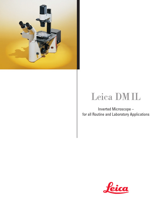
Leica DM ILInverted Microscope –for all Routine and Laboratory Applications2Leica Design by Ernest Igl /Christophe ApothélozLeica DM IL – compact inverted microscope for laboratory routine The new inverted Leica microscope blends ergonomy, a compactdesign and effective contrasting methods into a system for virtuallyunlimited life science applications.The integration of Leica HCS* optics extends the range of objectivesfor inverted microscopy.For the first time, high-quality relief contrast can be producedwithout special objectives with our new Integrated ModulationContrast (IMC) technique.Optimised phase contrast and brilliant incident light fluorescencemake the Leica DM IL the number one choice in contrastingmicroscopes.3With its unbeatable modularity, ergonomy and free view of thespecimen, teamed with newly developed and optimised contrastingtechniques, the Leica DM IL offers you a top level introduction toinverted microscopy.The adaption of the Leica DM IL to infinity optics allows theintegration of Leica HCS* components for superb image resolution,brilliant contrast and precise colour rendering. The DM IL is theinverted equivalent of our successful upright DM microscopes ofthe L and R class.The Leica DMIL is a microscope for all applications in microbiologyor the cell culture laboratory. A universal inverted microscope forroutine use: stable and space-saving, flexible and upgradablewith optics from Leica’s research microscopes.* Harmonic Component System Microinjection of oocytes in mouseRNA microinjection of frog oocytes(Xenopus)4The stand The stand of the Leica DM IL microscope is stable, aluminium-cast and excellently designed. There are two versions for biological applications:The DM IL for brightfield, phase and modulation contrast and the DM IL with additional incident light fluorescence unit.Appreciated by users for many years, the stable T-shaped micro-scope base offers plenty of valuable space round the microscope and ensures comfortable, fatigue-free microscopy. The micro-scope’s footprint is optimised to provide the necessary room for experiments, and all controls are ergonomically located. Many different components can be adapted to suit individual require-ments. The high stability, low centre of gravity and four vibration damping feet eliminate vibrations even in extreme conditions. The excellent stability of the DM IL also makes it the ideal solution for photography with long exposure times. In addition, finite element calculations and thorough practical testing in a wide variety of applications guarantee focusing which is not only ultra precise but also stable over long periods of time.The Leica DMIL contrasting microscopeThe System Discussion unitCardiac muscle cells5Due to its modularity, the Leica DM IL is particularly suitable forliving cell microscopy.Its modern, practical design, the integration of state-of-the-art,top quality optics and the excellent standard of the adaptedcontrasting techniques prove useful in research tasks as well asroutine applications.You will be convinced by the DM IL’s first-class technology andmany innovative and practical ideas.We at Leica believe microscopy should be a pleasurable experienceand designed the DM IL to be associated with enjoyment at thelaboratory workplace.Trinocular tube with DC 100Ergonomic phototubeTrinocular tube with MPS DM IL with illumination column the other way round6Nosepiece focusingSamples are focused with the quadruple objective nosepiece.The reliability, stability and precision of the focusing is not influenced by the microscope stage and the samples on it or by accessory components such as the object guide and manipulators.Illumination system The compact brightfield illumination unit is attached to a column and can be comfortably adjusted. Setting the correct height for the condenser used or the specimen on the stage is facilitated by markings along the column. The pre-centred, extremely powerful 6V 35W halogen lamp provides optimal illumination even of critical specimens. The transmitted light illumination concept is rounded off by the integration of the contrast slide (for phase and modulation contrast), the module for light filters with 32 mm diameter and the aperture diaphragm. The microscope stage with illumination arm can be turned round by 180°and is freely accessable for sample positioning from three sides.Light filters The filter module on the illumination column accommodates 32 mm diameter filters in a spoon-shaped holder. We are constantly adding to our wide range of filters, enabling you to selectively optimise the illumination for observation and image documentation.Built-in 6V 35W power supply The 6V 35W power supply, which provides the full lamp power including on/off switch, status indicator and brightness adjustment,is fully integrated in the microscope stand. Apart from the ergonomic advantages, this saves space on the microscope desk and allows the microscope to be easily picked up as a unit and moved elsewhere.The Technology7CondensersThe Leica DM IL offers you a choice of two condensers.The S 90/0.23 condenser with a free working distance of 90 mm and a numerical aperture of 0.23 is designed for brightfield and phase contrast and is particularly suitable for specimens in bulky laboratory vessels.The S 55/0.35 condenser with a free working distance of 55 mm and a numerical aperture of 0.35 for bulky containers is designed for brightfield, phase and integrated modulation contrast (IMC)and is particularly suitable for higher magnifications or thick specimens.Without a condenser, the maximum free working distance is 200 mm.Stage and accessoriesThe DM IL offers a wide variety of stages with a whole array of accessories and different inserts for your specimen vessels:The standard stage is a fixed stage plate of 252 x 212 mm. The stage can be widened by 70 mm on both sides by adapter plates. The interchangeable stage inserts (20-50 mm) allow smaller petri dishes to be used as well without losing the focus when the objective nosepiece is rotated.Object guides can be attached to both the left and right of the stage and have a minimum adjustment range of 83 x 127 mm. The control of the coaxial drive is in an ergonomically low position so that you can rest your hands on the desk while scanning specimens.The object guides accommodate special and multi-purpose frames for all types of culture vessels.A heating stage up to max. 45°C, a 3-plate mechanical stage and scanning stages round off the range of stages for the DM IL.Micromanipulation ...... and scanning stage8DM LB tubeEyepieces and objectivesThe optics are the heart of every microscope and decisive for the quality of information. We have set new standards here by intro-ducing our HC optics.The Leica DM IL is designed for brightfield, phase contrast, Inte-grated Modulation Contrast (IMC) and incident light fluorescence.All infinity-corrected high performance objectives in the Leica range with 25 mm screw thread are compatible with the DM IL microscope.Even earlier-type Leica objectives can be adapted for use on the DM IL. We offer a wide range of special objectives for inverted microscopy applications with long free working distances (L objectives) and/or with correction mounts (Corr objectives) to compensate for different vessel thicknesses. The latest Leica optics brochure features our whole range of objectives.Depending on the tube configuration, there is a wide choice of eyepieces with magnifications 10x, 12.5x, 15x, 16x or 25x, suitable for fields of view up to 20 mm. Besides special high-point eyepieces for eyeglass wearers, we also supply eyepieces with adjustable eyelens (M eyepieces), into which different types of graticule can be inserted.The DM IL range also comprises many different observation and photo tubes. The tubes are interchangeable and can be individually rotated by 360°in the tube mount and then fixed in position. All tubes are fitted with an infinity tube lens 1x. The following tubes are used on the DM IL:•Binocular tube ILB, with 45°viewing angle, for eyepieces with 23.2 mm outer diameter •Trinocular (photo)tube ILT, with 45°viewing angle, for eyepieces with 23.2 mm outer diameter, with vertical photo/TV exit with switchable light path for either 100% visual or 100% photo/TV.The position of the photo/TV exit 88 mm to the side of the tube has the special advantage that it allows an unobstructed view of the specimen.Other tubes from the Leica DM L range can be used via an IL/L adapter:•Binocular tube HC LB 45°viewing angle •Binocular tube HC LVB 0-35°ergotube •Trinocular (photo)tube HC L1T 45°viewing angle •Trinocular (photo)tube HC L3T 45°viewing angle •Trinocular (photo)tube HC LV1T 0-35°ergotubeThe Optics351+364 mn UVAr 488mn 568mn 647mn Ar/Kr 4905205575766486703504004505005506006507009Developments in diagnostics and med./biol. research (e.g. fluores-cence applications) and the increasing use of video technology and electronic image processing have to be paralleled by intelligent technical adaptations of the microscope system.The new HCS optics concept introduced with the Leica DM R microscope meets this requirement. It is the result of an integral system consideration, harnessing all technological potential.The abbreviation HCS stands for Harmonic Component System.Its special features are:•well-balanced optical and mechanical fitting dimensions•harmonious balance of all optical system components, i.e. the parameters contributing to the microscope’s performance (objectives, tube lenses, tubes, eyepieces, TV cameras/adapters,etc.) have been harmonised throughout the entire optic system.This has created scope for even greater optical opportunities.The HCS system is the answer to your application requirements not only today, but in future, too.Rat testicles, IMC10The Leica DM IL is the microscope for all requirements in the cell culture lab. A universal inverted microscope for routine application: stable and space-saving, flexible and upgradable with optics from Leica research microscopes.BrightfieldThe whole range of objectives from 4x-100x magnification can be used for brightfield applications. Samples in almost any kind of vessel can be examined with or without a condenser, while a 6V 35W halogen lamp ensures optimal illumination.Phase contrastIn vivo/ in vitro microscopy specimens are mostly living cultures or microorganisms and are examined under sterile conditions. Contrast of the transparent tissue can only be enhanced by optical methods.Phase contrast is a useful technique for high-contrast imaging of unstained specimens. The phase contrast technique used by Leica on the DM IL has been optimised for inverted microscopy applications and produces equally excellent contrast in watery solutions and of dry preparations in petri dishes.Spinal cord, catContrastingLymphocyte toxicity testdouble staining, strongly positiveLymphocyte toxicity testdouble staining, weakly positive11Human brain Femtotip microinjection needle (Photo: Eppendorf)FibroblastsIMC (Integrated Modulation Contrast)The innovative technique of Integrated Modulation Contrast (IMC)now introduced by Leica in the DM IL is based on Hoffman’sprinciple and produces this contrast without the need for specialobjectives–ordinary brightfield or phase contrast objectives canbe used. The Leica IMC provides a high-contrast, 3D image oftransparent objects similar to that of interference contrast. Plasticculture vessels do not impair the quality of the image as thetechnique is polarisation-neutral.The diaphragm slide on the side of the illumination and theswitchable modulator in the intermediate image of the pupilproduce the type of contrast named after Hoffman without modi-fying the objectives. High contrast, high resolution, a halo-freerelief image of either stained or unstained specimens make Leica’sIMC a new standard in the class of inverted routine microscopy.FluorescenceThe fluorescence model of the DM IL reflects the growing signifi-cance of fluorescence for in vivo/in vitro microscopy. The maincomponents of this configuration are an incident light axis integrat-ed in the microscope stand, incorporating a fluorescence slide forthree filter cubes. A wide range of light sources with multi-lens,chromatically corrected collectors brighten up even the weakestfluorescence. The fluorescence filter cubes comprise an optimallymatched combination of excitation, reflection, band-pass andbarrier filters. We are constantly updating our range of filtercubes to keep pace with the latest challenges in biology andmedicine.Transmitted light techniques can be used simultaneously or inalternation in order to clearly allocate fluorescent and non-fluorescent structures.The Leica DM IL offers you a powerful system for immunology,cytopathology, virology – in fact wherever fluorescence techniquesare used in combination with inverted microscopy.Leica Microsystems – the brand for outstanding products Microscopes Compound Stereo Surgical Laser Scanning Photomicrography Video Microscopy Measuring Microscopes Advanced Systems Image Analysis Spectral Photometry Automated Inspection Stations Measurement Systems Electron Beam Lithography Laboratory equipment Tissue Processors Embedding Systems Routine- & Immunostaining Coverslippers Refractometers Microtomes Sliding, Rotary & Disc Cryostats Ultramicrotomes EM Sample Preparation Leica Microsystems’ Mission is to be the world’s first-choice provider of innovative solutions to our customers’ needs for vision, measurement, lithography and analysis of microstructures.Leica, the leading brand for microscopes and scientific instruments, has developed from five brand names, all with a long tradition: Wild, Leitz, Reichert, Jung and Cambridge Instruments. Leica symbolizes not only tradition, but also innovation.Leica Microsystems – an international company with a strong network of customer servicesAustralia:North Ryde/NSW Tel. +61 2 9879 9700Fax +61 2 9817 8358Austria:Vienna Tel. +43 1 495 44 160Fax +43 1 495 44 1630Canada:Willowdale/Ontario Tel. +1 416 497 2860Fax +1 416 497 8516Denmark:Herlev Tel. +45 4454 0101Fax +45 4454 0111Finland:Espoo Tel. +358 9 6153 555Fax +358 9 5022 398France:Rueil-Malmaison Tel. +33 1 473 285 85Fax +33 1 473 285 86CedexGermany:Bensheim Tel. +49 6251 136 0Fax +49 6251 136 155Italy:Milan Tel. +39 0257 486.1Fax +39 0257 40 3273Japan:Tokyo Tel. +81 3 5435 9600Fax +81 3 5435 9618Korea:Seoul Tel. +82 2 514 65 43Fax +82 2 514 65 48Netherlands:Rijswijk Tel. +31 70 4132 100Fax +31 70 4132 109Portugal:Lisbon Tel. +351 1 388 9112Fax +351 1 385 4668Republic of China:Hong Kong Tel. +852 2564 6699Fax +852 2503 4826Singapore:Tel. +65 779 7823Fax +65 773 0628Spain:Barcelona Tel. +34 93 494 95 30Fax +34 93 494 95 32Sweden:Sollentuna Tel. +46 8 625 45 45Fax +46 8 625 45 10Switzerland:Glattbrugg Tel. +41 1 809 34 34Fax +41 1 809 34 44United Kingdom:Milton Keynes Tel. +44 1908 246 246Fax +44 1908 609 992USA:Deerfield/Illinois Tel. +1 847 405 0123Fax +1 847 405 0030and representatives of Leicain more than 100 countries.Leica Microsystems Wetzlar GmbH Ernst-Leitz-Straße D-35578 Wetzlar (Germany)Tel. +49 (0)6441-290Fax +49 (0)6441-292599 ©L e i c a M i c r o s y s t e m s W e t z l a r G m b H •E r n s t -L e i t z -S t r a ße •35578 W e t z l a r •T e l. (06441) 29-0 •F a x (06441) 29-2599 G e d r u c k t a u f c h l o r f r e i g e b l e i c h t e m P a p i e r .B e s t e l l -N u m m e r n d e r A u s g a b e n i n : D e u t s c h 913 761•E n g l i s c h 913 762 •F r a n z ös i s c h 913 763 •I t a l i e n i s c h 913 764 •S a c h -N r . 501-068 G e d r u c k t i n D e u t s c h l a n d X I /98/A X /B .H .。
- 1、下载文档前请自行甄别文档内容的完整性,平台不提供额外的编辑、内容补充、找答案等附加服务。
- 2、"仅部分预览"的文档,不可在线预览部分如存在完整性等问题,可反馈申请退款(可完整预览的文档不适用该条件!)。
- 3、如文档侵犯您的权益,请联系客服反馈,我们会尽快为您处理(人工客服工作时间:9:00-18:30)。
①放大部件是? 放大倍数= 目镜×物镜
②能调节视野亮度
的部件是? 反光镜、遮光器
③调焦部件是?
粗、细准焦螺旋
光
2.显微镜的使用--低倍镜
取镜和安放
升镜筒 转到低倍镜 对光 调遮光器(大光圈) 调反光镜 安放标本 (标本对准通光孔中央) 看物镜,降镜筒 观察 看目镜,升镜筒 移动标本、观察
4.某同学在显微镜下观察花生种子子叶的切 片时,当转动细准焦螺旋时,有一部分 细胞看得清晰,另一部分细胞比较模糊, B 这是由于( ) A.反光镜未调节好 B.标本切得厚薄不均 C.细准焦螺旋未调节好 D.显微镜物镜已损坏
5.右图为显微镜观察中的两个视野,其中细 胞甲为主要观察对象,若要由视野Ⅰ变为 视野Ⅱ,下列操作过程中,正确的顺序是 D ①转动粗准焦螺旋 ②转动细准焦螺旋 ③调节光圈 ④转动转换器 ⑤向左下方移动玻片 ⑥向右上方移动玻片 A.①③④⑤ B.⑤③④② C.⑥④③② D.⑤④③②
2. 观察玻片标本时,若发现视野上方较暗 下方较亮,应调节( D ) A. 目镜 B. 物镜 C. 遮光器 D. 反光镜 3.在显微镜低倍镜下发现视野内有一个污点。 移动装片后,污点位置不变,转换高倍 C 镜后,污点消失。由此可判断污点位于 ( ) A. 装片 B. 目镜 C. 低倍物镜 D. 高倍物镜
6.显微镜目镜为10×,物镜为10×,视野中 被相连的64个细胞所充满。若物镜转换为 40×后,则在视野中可检测到的细胞数为 ( B )
A.2个
C.8个
B.4个
D.16个
视野亮度的调节
♧ 反光镜:平面镜 ♧ 遮光器:大光圈
/ 凹面镜 / 小光圈
♧ 观察颜色较浅的标本时应选用? 平面镜、小光圈
♧ 由低倍镜转用高倍镜后,视野亮度有什么
还原和整理
3.高倍镜的使用
步骤: ①低倍镜下将物像调清晰 ②将要观察的物像移到视野中央 ③直接换用高倍镜 ④调节视野亮度 ⑤用细准焦微调
怎样将细胞A移到视野中央?
向右下移玻片。
小练习
1. 用显微镜的一个目镜分别与4个不同倍数 的物镜组合观察洋葱表皮细胞装片。当成 像清晰时,每一物镜与载玻片的距离如下 图所示。如果载玻片的位置不变,用哪一 物镜在一个视野中看到的细胞最多( A )
变化?怎样处理? 变暗; 调节遮光器或反光镜
结构