ECTE364-Lect9
菲尼克斯PLC继电器-
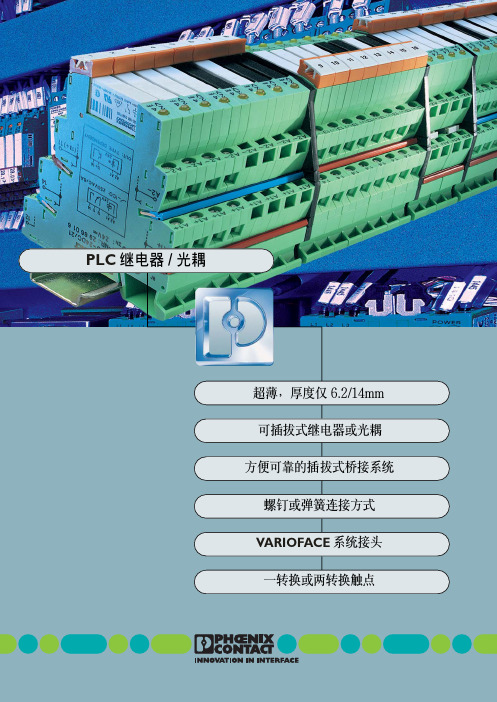
灵活 性意味 着根据 应用场 合既 可以为 每 个通道 自由选 择输入电 压,也可以 装入不 同 的机电式继 电器或者半导 体继电器 (光电 耦 合器) 。固 定的可编程控制 器插件板在这 方 面也是 望尘莫 及。灵活性 也意味着 系统可 以 随时 扩展,并且 可以随 时方便、便 宜地更 换 可插拔式继电器和光电耦合器。
PLC 接口 带回拉式弹簧连接 由 底座接线端子 PLC-BSP…/21 和 可插拔微型继电器组成, 用于安装在 3 上
输入电压 UN
12VDC 24VDC 24VAC/DC 48VDC 60VDC 120VAC/110VDC 230VAC/220VDC2)
12VDC 24VDC 24VAC/DC 48VDC 60VDC 120VAC/110VDC 230VAC/220VDC2)
VARIOFACE 系统接头
(164,)2 mm
可插拔继电器 和光电耦合器,
6.2/14mm
插拔式桥接系统
两个转换 触点 传感器型 执行器型 通用型
按实际应用优化的 系列产品
I
250VAC/6A(10A)
可选用螺钉连接或者回拉式 弹簧连接两种形式
U 通断容量高
一体化集成输入电路 和保护电路
DINVDE0106-101
执行 器 (例如 电磁阀、接 触器等)的 所 有连接线 (包括回线) 都被直接连接在 PLC 执行器接口上。
传感 器 (例 如接 近开 关、限位 开关 等) 的所有连 接线 (包括开 关的供电)都直 接在 PLC 接口上有相应的连接位置。与传统的耦 合元 件相比,可以 节省两 个输出 接线端子 或 者馈 入连接端 子,同时节 省了中 间接线工 作 和宝贵的开关柜空间。
施耐德接触器选型样本

b TeSys D 型 3 极热过载继电器 . . . . . . . . . . . . . . . . . . . . . . . . . . . . . . . . . . . . . . 3/2 b 说明,特性. . . . . . . . . . . . . . . . . . . . . . . . . . . . . . . . . . . . . . . . . . . . . . . . . . . . . 3/3 b 型号 . . . . . . . . . . . . . . . . . . . . . . . . . . . . . . . . . . . . . . . . . . . . . . . . . . . . . . . . . . 3/5 b 附件 . . . . . . . . . . . . . . . . . . . . . . . . . . . . . . . . . . . . . . . . . . . . . . . . . . . . . . . . . . 3/9 b 尺寸,安装,线路图 . . . . . . . . . . . . . . . . . . . . . . . . . . . . . . . . . . . . . . . . . . . . 3/11
v 用于至 75 kW/400V 的电动机控制, AC-3 类别 . . . . . . . . . . . . . . . . . . . . . 1/12 v 用于至 15 kW/400V 的电动机控制, AC-3 类别 . . . . . . . . . . . . . . . . . . . . . 1/13 v 用于 25 至 200A 的电路控制, AC-1 类别 . . . . . . . . . . . . . . . . . . . . . . . . . . 1/18 b 用于电动机控制的可逆接触器, AC-3 类别 v 75 kW/400V . . . . . . . . . . . . . . . . . . . . . . . . . . . . . . . . . . . . . . . . . . . . . . . . 1/20 v 15 kW/400V . . . . . . . . . . . . . . . . . . . . . . . . . . . . . . . . . . . . . . . . . . . . . . . . 1/21 b 电源转换接触器组,用于 AC-1 负载控制 v 20 至 200 A . . . . . . . . . . . . . . . . . . . . . . . . . . . . . . . . . . . . . . . . . . . . . . . . . 1/22 b 根据所需电气寿命选型 v AC-3 使用类别 . . . . . . . . . . . . . . . . . . . . . . . . . . . . . . . . . . . . . . . . . . . . . . . 1/24 v AC-2 或 AC-4 使用类别 . . . . . . . . . . . . . . . . . . . . . . . . . . . . . . . . . . . . . . . . 1/27 v AC-1 使用类别 . . . . . . . . . . . . . . . . . . . . . . . . . . . . . . . . . . . . . . . . . . . . . . . 1/30 v DC-1 至 DC-5 使用类别 . . . . . . . . . . . . . . . . . . . . . . . . . . . . . . . . . . . . . . . . 1/32 b 可逆接触器的装配元件. . . . . . . . . . . . . . . . . . . . . . . . . . . . . . . . . . . . . . . . . . . 1/35 b 辅助模块与附件 . . . . . . . . . . . . . . . . . . . . . . . . . . . . . . . . . . . . . . . . . . . . . . . . 1/38 b D 型接触器线圈 v 交流线圈 . . . . . . . . . . . . . . . . . . . . . . . . . . . . . . . . . . . . . . . . . . . . . . . . . . . 1/45 v 直流线圈 . . . . . . . . . . . . . . . . . . . . . . . . . . . . . . . . . . . . . . . . . . . . . . . . . . . 1/48 v 宽电压范围直流线圈 . . . . . . . . . . . . . . . . . . . . . . . . . . . . . . . . . . . . . . . . . . 1/50 b 尺寸,安装与线路图 . . . . . . . . . . . . . . . . . . . . . . . . . . . . . . . . . . . . . . . . . . eSys D 型控制继电器特性 . . . . . . . . . . . . . . . . . . . . . . . . . . . . . . . . . . . . . . . . 2/2 b 用于控制电路:交流,直流或低功耗 . . . . . . . . . . . . . . . . . . . . . . . . . . . . . . . . . 2/6 b 辅助模块 . . . . . . . . . . . . . . . . . . . . . . . . . . . . . . . . . . . . . . . . . . . . . . . . . . . . . . 2/8 b 附件和备件. . . . . . . . . . . . . . . . . . . . . . . . . . . . . . . . . . . . . . . . . . . . . . . . . . . . . 2/9
Agilent E364xA系列可编程DC电压源数据手册说明书

Agilent Technologies E3640A – E3649A Programmable DC Power SuppliesData SheetGreat Performance, Outstanding Price With 30 to 100W of output power, the Agilent E364xA-series ofprogrammable DC power supplies provide great performance at a great price. All ten models deliver clean power, dependable regulation, fast transient response and built-in GPIB and RS-232 interfaces. They’re designed to meet the needs of R&D design verification, production testing, QA verifications and other demandingapplications with Agilent Technologies’quality and reliability.Steady OutputWith 0.01 percent load and line regulation, Agilent E364xA power supplies keep output steady when power line and load changes occur.They also specify low normal mode voltage noise and low common mode current noise. The low normal mode noise specification assures clean power for precision circuitry applications, and the low common mode currentprovides isolation from power line current injection. Agilent E364xA power supplies specify less than 90msec of voltage settling time at any output load condition.Remote InterfaceAgilent E364xA power supplies support any PC with a GPIB (IEEE-488) card or RS-232 interface. Every model ships standard with both GPIB and RS-232.Easy-to-use SCPI (Standard Commands for Programmable Instruments) keeps programming fast and simple. The user manual provides information for beginning programmers, yet includes enough detail to help veteran programmers as well. Broad SupportVXIplug&play software drivers are available for Agilent VEE and National Instruments LabView™ andLabWindows™, simplifying integration of the E364xA into your test system.The drivers are supported under Microsoft ®Windows 98®and NT.®Front Panel OperationAn easy-to-use rotary knob and self-guiding keypads allow you to quickly and easily set output at the resolution you need. Voltage and current levels can be set to a maximum resolution of 10mV/1 mA from the front panel. Up to five complete power supply setups can be stored and recalled from the internal non-volatile memory. The output on/off button sets the output to zero. Dual output models allow two voltages or currents to be displayed simultaneously. Versatile PowerAgilent E364xA power supplies give you the flexibility to select from dual output ranges. Output load is protected against overvoltage, which is easily monitored and adjusted from the front panel and remote interface. Remote sensing is available in the rear terminal to eliminate errors due to voltage drops on the load leads. These power supplies offer new versatile bindingClean Programmable Power Supplies • Single and Dual Output • Dual Output Ranges • 30W to 100W Output Power • Front and Rear Output Terminals • Over-voltage Protection • Remote Sense• GPIB and RS-232 Standardposts on the front panel and screw-type terminals on the rear panel. New front panel binding posts allow you to use safety test leads as well as conventional banana clips and stripped wires. An optional rackmount kit is available. The Agilent E364xA series employs a cooling fan with automatic speed control for reduced acoustic noise. LabView and LabWindows are registered trademarks ofNational Instruments.Microsoft, Windows 98 and Windows NT are US registered trademarks of Microsoft Corp.Highly visible vacuum flourescent displaySelectable dual range provides flexibility and convenience3-year warranty protects yourBuilt-in GPIB and RS-232 interfaces Rotary knob for quick and analog-like control of voltage and currentVersatile binding posts offer flexibility to use safety test leads, banana plugs orRear output and sensing terminals Cooling fan with automatic speed control for low acoustic noiseTough handlefor easycarriage andunit prop-up2Agilent E3640A – E3649A Programmable DC Power Supply SpecificationsModel Number E3640A E3641A E3642A E3643A E3644A E3645AMaximum Power30W50W80W# of Output111111DC Output Rating0 to 8V/3A or0 to 35V/0.8A or0 to 8V/5A or0 to 35V/1.4A or 0 to 8V/8A or0 to 35V/2.2A or(@ 0°C to 40°C)0 to 20V/1.5A0 to 60V/0.5A0 to 20V/2.5A0 to 60V/0.8A0 to 20V/4A0 to 60V/1.3ANet Weight 5.3kg (11.7 lbs) 6.2kg (13.7 lbs) 6.7 kg (14.7 lbs)Dimension254.4mmW x 103.6mmH x 374mmD (10 x 4.1 x 14.7 in)Model Number E3646A E3647A E3648A E3649AMaximum Power60W100W# of Output2222DC Output Rating Two Two Two Two (@ 0°C to 40°C)0 to 8V/3A or0 to 35V/0.8A or 0 to 8V/5A or0 to 35V/1.4A or0 to 20V/1.5A0 to 60V/0.5A0 to 20V/2.5A60V/0.8ANet Weight7.3kg (16.1 lbs)9.2kg (20.3 lbs)Dimension228mm W x 133mm H x 374mm D (8.9 x 5.2 x 14.7 in)Load1and Line Regulation±(% of output + offset)Voltage<0.01% + 3mVCurrent<0.01% + 250uARipple and Noise(20Hz to 20MHz)Normal Mode Voltage<5mVpp/0.5mVrms for 8V/20V models<8mVpp/1mVrms for 35V/60V modelsNormal Mode Current<4mArmsCommon Mode Current<1.5uArmsAccuracy 12 Months (@ 25 °C ±5 °C), ±(% output + offset)ProgrammingVoltage<0.05% + 10mV (<0.1% + 25mV for output 2 of E3646/47/48/49A)Current<0.2% + 10mAReadbackVoltage <0.05% + 5mV (<0.1% + 25mV for output 2 of E3646/47/48/49A)Current<0.15% + 5mA (<0.15% + 10mA for output 2 of E3646/47/48/49A)ResolutionProgram<5mV / 1mAReadback<2mV / 1mAMeter10mV / 1mATransient Response Less than 50µsec for output to recover to within 15mV following a change in outputcurrent from full load to half load or vice versa.Settling Time 2<90msecOVPAccuracy,<0.5% + 0.5V±(% output + offset)Activation time3<1.5msec, OVP≥3V / <10msec, OVP< 3VTemperature Coefficient per °C±(% output + offset)Voltage<0.01% + 3mV (<0.02% + 5mV for output 2 of E3646/47/48/49A)Current<0.02% + 3mAStability, constant output & temperature ±(% of output + offset), 8 hrsVoltage <0.02%+2mVCurrent<0.1% + 1mARemote Sense 1VMax voltage drop in each load leadAC Input 100Vac ±10% (Opt 0E9) / 115Vac ±10% (Std) / 230Vac ±10% (Opt 0E3)(47Hz – 63Hz)Warranty 3 yearsProduct Regulation Designed to comply with UL3111-1; certified to CSA 22.2 No. 1010.1; conforms toIEC 1010-1; complies with EMC directive 89/336/EEC(Group1, Class A)1With sense terminal connected.2Maximum time required for the output voltage to change from 1% to 99% or vice versa following the receipt of VOLTage orAPPLy command via direct GPIB or RS-232 interface.3Average time for output to start to drop after OVP condition occurs.3sliding support shelf Shelf (P/N 5063-9256) Slide Kit (P/N 1494-0015)Data subject to change.© Agilent Technologies 2000 Printed in the U.S.A. 02/00 5968-7355EN。
施耐德E型接触器
选型指南.............................................................................................................. 24 说明,特性 ..........................................................................................................25 热过载继电器选型.............................................................................................27 尺寸及安装 ......................................................................................................... 28
2 根导线
mm2 1...4
1...4
1...4
1...2.5
1...4
软线
1 根导线
mm2 1...4
1...4
1...4
1...2.5
1...4
带接线端子
2 根导线
mm2 1...2.5
1...2.5
1...2.5
1...2.5
1...2.5
硬线
1 根导线
mm2 1...4
1...4
1.5...6
1
选型指南
应用
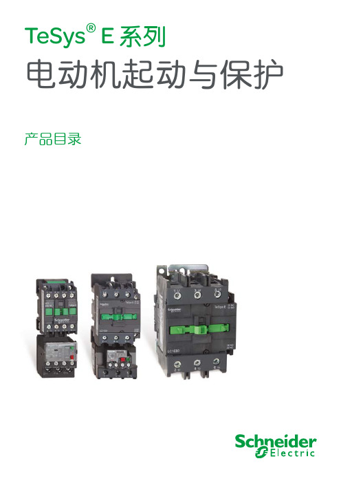
TeSys® E 接触器
LC1E06到E95
各种类型的控制系统
NI 9220 16 AI, ±10 V, 16 Bit, 100 kS s ch Simultan
GETTING STARTED GUIDENI 922016 AI, ±10 V, 16 Bit, 100 kS/s/ch SimultaneousThis document explains how to connect to the NI 9220. In this document, the NI 9220 with spring terminal and the NI 9220 with DSUB are referred to inclusively as the NI 9220.Note Before you begin, complete the software andhardware installation procedures in your chassisdocumentation.Note The guidelines in this document are specific tothe NI 9220. The other components in the system mightnot meet the same safety ratings. Refer to thedocumentation for each component in the system todetermine the safety and EMC ratings for the entiresystem.Caution Electrostatic Discharge (ESD) can damagethe NI 9220 with spring terminal. To prevent damage,use industry-standard ESD prevention measures duringinstallation, maintenance, and operation.Safety GuidelinesOperate the NI 9220 only as described in this document.2| | NI 9220 Getting Started GuideCaution Do not operate the NI 9220 in a manner notspecified in this document. Product misuse can result ina hazard. You can compromise the safety protectionbuilt into the product if the product is damaged in anyway. If the product is damaged, return it to NI forrepair.Hazardous Voltage This icon denotes a warningadvising you to take precautions to avoid electricalshock with the NI 9220 with spring terminal. Safety VoltagesConnect only voltages that are within the following limits:NI 9220 with Spring Terminal Isolation Voltages Channel-to-channel NoneChannel-to-earth groundContinuous250 Vrms,Measurement Category IIWithstand up to 4,000 m 3,000 Vrms, verified by a 5 s dielectric withstand testNI 9220 Getting Started Guide| © National Instruments| 3Measurement Category II is for measurements performed on circuits directly connected to the electrical distribution system. This category refers to local-level electrical distribution, such as that provided by a standard wall outlet, for example, 115 V for U.S. or 230 V for Europe.Caution Do not connect the NI 9220 with springterminal to signals or use for measurements withinMeasurement Categories III or IV.NI 9220 with DSUB Safety VoltagesChannel-to-COM±30 V maximumIsolationChannel-to-COM NoneChannel-to-earth groundContinuous60 VDC, MeasurementCategory IWithstand up to 2,000 m 1,000 Vrms, verified by a 5 s dielectric withstand testMeasurement Category I is for measurements performed on circuits not directly connected to the electrical distribution system 4| | NI 9220 Getting Started Guidereferred to as MAINS voltage. MAINS is a hazardous live electrical supply system that powers equipment. This category is for measurements of voltages from specially protected secondary circuits. Such voltage measurements include signal levels, special equipment, limited-energy parts of equipment, circuits powered by regulated low-voltage sources, and electronics.Caution Do not connect the NI 9220 with DSUB tosignals or use for measurements within MeasurementCategories II, III, or IV.Safety Guidelines for Hazardous VoltagesYou can connect hazardous voltages only to theNI 9220 with spring terminal. Do not connect hazardous voltages to the NI 9220 with DSUB.If hazardous voltages are connected to the device, take the following precautions. A hazardous voltage is a voltage greater than 42.4 Vpk voltage or 60 VDC to earth ground.Caution Ensure that hazardous voltage wiring isperformed only by qualified personnel adhering to localelectrical standards.NI 9220 Getting Started Guide| © National Instruments| 5Caution Do not mix hazardous voltage circuits andhuman-accessible circuits on the same module.Caution Ensure that devices and circuits connected tothe module are properly insulated from human contact.Caution When module terminals are hazardousvoltage LIVE (>42.4 Vpk/60 VDC), you must ensurethat devices and circuits connected to the module areproperly insulated from human contact. You must usethe NI 9940 connector backshell kit to ensure that theterminals are not accessible.Safety Guidelines for Hazardous LocationsThe NI 9220 is suitable for use in Class I, Division 2, Groups A, B, C, D, T4 hazardous locations; Class I, Zone 2, AEx nA IIC T4 and Ex nA IIC T4 hazardous locations; and nonhazardous locations only. Follow these guidelines if you are installing the NI 9220 in a potentially explosive environment. Not following these guidelines may result in serious injury or death.Caution Do not disconnect I/O-side wires orconnectors unless power has been switched off or thearea is known to be nonhazardous.6| | NI 9220 Getting Started GuideCaution Do not remove modules unless power hasbeen switched off or the area is known to benonhazardous.Caution Substitution of components may impairsuitability for Class I, Division 2.Caution For Division 2 and Zone 2 applications,install the system in an enclosure rated to at least IP54as defined by IEC/EN 60079-15.Caution For Division 2 and Zone 2 applications,connected signals must be within the following limits. Capacitance0.2 µF maximumSpecial Conditions for Hazardous Locations Use in Europe and InternationallyThe NI 9220 has been evaluated as Ex nA IIC T4 Gc equipment under DEMKO 12 ATEX 1202658X and is IECEx UL 14.0089X certified. Each NI 9220 is marked II 3G and is suitable for use in Zone 2 hazardous locations, in ambient temperatures of -40 °C ≤ Ta ≤ 70 °C. If you are using the NI 9220 in Gas Group IIC hazardous locations, you must use the device in an NI chassis thatNI 9220 Getting Started Guide| © National Instruments| 7has been evaluated as Ex nC IIC T4, Ex IIC T4, Ex nA IIC T4, or Ex nL IIC T4 equipment.Caution You must make sure that transientdisturbances do not exceed 140% of the rated voltage.Caution The system shall only be used in an area ofnot more than Pollution Degree 2, as defined inIEC/EN 60664-1.Caution The system shall be mounted in anATEX/IECEx-certified enclosure with a minimumingress protection rating of at least IP54 as defined inIEC/EN 60079-15.Caution The enclosure must have a door or coveraccessible only by the use of a tool.Electromagnetic Compatibility Guidelines This product was tested and complies with the regulatory requirements and limits for electromagnetic compatibility (EMC) stated in the product specifications. These requirements and limits provide reasonable protection against harmful interference 8| | NI 9220 Getting Started Guidewhen the product is operated in the intended operational electromagnetic environment.This product is intended for use in industrial locations. However, harmful interference may occur in some installations, when the product is connected to a peripheral device or test object, or if the product is used in residential or commercial areas. To minimize interference with radio and television reception and prevent unacceptable performance degradation, install and use this product in strict accordance with the instructions in the product documentation.Furthermore, any changes or modifications to the product not expressly approved by National Instruments could void your authority to operate it under your local regulatory rules.Caution To ensure the specified EMC performance ofthe NI 9220 with DSUB, the length of all I/O cablesmust be no longer than 30 m (100 ft).Caution To ensure the specified EMC performance,operate this product only with shielded cables andaccessories. Do not use unshielded cables oraccessories unless they are installed in a shieldedenclosure with properly designed and shielded input/NI 9220 Getting Started Guide| © National Instruments| 9output ports and connected to the product using ashielded cable. If unshielded cables or accessories arenot properly installed and shielded, the EMCspecifications for the product are no longer guaranteed. Special Conditions for Marine ApplicationsSome products are Lloyd’s Register (LR) Type Approved for marine (shipboard) applications. To verify Lloyd’s Register certification for a product, visit /certification and search for the LR certificate, or look for the Lloyd’s Register mark on the product.Caution In order to meet the EMC requirements formarine applications, install the product in a shieldedenclosure with shielded and/or filtered power andinput/output ports. In addition, take precautions whendesigning, selecting, and installing measurement probesand cables to ensure that the desired EMC performanceis attained.10| | NI 9220 Getting Started GuidePreparing the EnvironmentEnsure that the environment in which you are using the NI 9220 meets the following specifications.Operating temperature(IEC 60068-2-1, IEC 60068-2-2)-40 °C to 70 °COperating humidity (IEC 60068-2-78)10% RH to 90% RH, noncondensingPollution Degree2Maximum altitudeFor NI 9220 withspring terminal4,000 mFor NI 9220 withDSUB2,000 mIndoor use only.Note Refer to the device datasheet on /manualsfor complete specifications.NI 9220 Getting Started Guide| © National Instruments| 11NI 9220 Pinout12| | NI 9220 Getting Started GuideGrounded Differential ConnectionsNI 9220 Getting Started Guide| © National Instruments| 13Floating Differential ConnectionsConnect the negative lead to COM through a 1 MΩ resistor to keep the signal source within the common-mode voltage range. The NI 9220 does not read data accurately if the signal source is outside of the common-mode voltage range.14| | NI 9220 Getting Started GuideSingle-Ended ConnectionsConnect the ground signal to COM to keep the signal source within the common-mode voltage range.NI 9220 Connection Guidelines•Make sure that devices you connect to the NI 9220 are compatible with the module specifications.•You must use 2-wire ferrules to create a secure connection when connecting more than one wire to a single terminal on the NI 9220 with spring terminal.NI 9220 Getting Started Guide| © National Instruments| 15•For the NI 9220 with spring terminal, push the wire into the terminal when using a solid wire or a stranded wire with aferrule.•For the NI 9220 with spring terminal, open the terminal by pressing the push button when using stranded wire without a ferrule.High-Vibration Application ConnectionsIf your application is subject to high vibration, NI recommends that you use the NI 9940 backshell kit to protect connections to the NI 9220 with spring terminal.Overvoltage ProtectionThe NI 9220 provides overvoltage protection for each channel.Note Refer to the device datasheet on /manualsfor more information about overvoltage protection.16| | NI 9220 Getting Started GuideWhere to Go NextLocated at /manuals NI 9220 Getting Started Guide | © National Instruments | 17Worldwide Support and ServicesThe NI website is your complete resource for technical support. At /support, you have access to everything from troubleshooting and application development self-help resources to email and phone assistance from NI Application Engineers. Visit /services for NI Factory Installation Services, repairs, extended warranty, and other services.Visit /register to register your NI product. Product registration facilitates technical support and ensures that you receive important information updates from NI.A Declaration of Conformity (DoC) is our claim of compliance with the Council of the European Communities using the manufacturer’s declaration of conformity. This system affords the user protection for electromagnetic compatibility (EMC) and product safety. You can obtain the DoC for your product by visiting /certification. If your product supports calibration, you can obtain the calibration certificate for your product at /calibration.18| | NI 9220 Getting Started GuideNI corporate headquarters is located at11500 North Mopac Expressway, Austin, Texas, 78759-3504. NI also has offices located around the world. For telephone support in the United States, create your service request at /support or dial 1 866 ASK MYNI (275 6964). For telephone support outside the United States, visit the Worldwide Offices section of /niglobal to access the branch office websites, which provide up-to-date contact information, support phone numbers, email addresses, and current events.NI 9220 Getting Started Guide| © National Instruments| 19Refer to the NI Trademarks and Logo Guidelines at /trademarks for information on NI trademarks. Other product and company names mentioned herein are trademarks or trade names of their respective companies. For patents covering NI products/technology, refer to the appropriate location: Help»Patents in your software, the patents.txt file on your media, or the National Instruments Patent Notice at /patents. Y ou can find information about end-user license agreements (EULAs) and third-party legal notices in the readme file for your NI product. Refer to the Export Compliance Information at /legal/export-compliance for the NI global trade compliance policy and how to obtain relevant HTS codes, ECCNs, and other import/ export data. NI MAKES NO EXPRESS OR IMPLIED WARRANTIES AS TO THE ACCURACY OF THE INFORMATION CONTAINED HEREIN AND SHALL NOT BE LIABLE FOR ANY ERRORS. U.S. Government Customers: The data contained in this manual was developed at private expense and is subject to the applicable limited rights and restricted data rights as set forth in FAR 52.227-14, DFAR 252.227-7014, and DFAR 252.227-7015.© 2017 National Instruments. All rights reserved.378023A-01Jan17。
HMTE在线氢气露点仪说明书ok

目录第一章简介 (2)第二章技术指标 (3)第三章HMT364E安装方案 (5)第四章电气连接 (6)图1:方案一直接进入DCS系统的电气接线图 (7)图2:方案二外供220VAC电源再进入DCS系统的电气接线图 (8)图3:氢气湿度测量仪现场安装示意图 (9)图4:HMT364E安装尺寸和元件布置图 (10)第五章操作 (11)第六章操作错误信息 (13)第七章显示屏/按键命令 (14)第八章串行口 (17)第九章校准 (22)第一章简介本质安全型的HMT364E(HMT364D+RLS-364G)在线露点测量仪,用于测量氢冷发电机组的氢气湿度,能在危险区域同时测量露点温度(Td)和温度(T)的防爆(EX)级别的仪表。
传感器探头安装的烧结过滤器不但防电磁干扰,而且还抗油污染。
HMT364E的采样系统由过滤器、排污装置、传感器套筒、流量计等组成。
通过观察流量范围,可得知前级过滤器是否被油污堵塞,并提醒及时清除。
清洗过程简单,且不影响发电机正常工作,而且提高了测量精度和稳定性,延长了探头的使用寿命,降低了维护工作量,减少了维修费用。
该采样系统易安装,操作简单且几乎属于免维护。
符合欧洲标准·EU 管理的76/117/EEC标准:EN50014和EN50020标定:EE x ia ⅡC T51:输出参数传感器有一个现场显示和两路电流输出信号。
传感器的测量和计算参数如下:参数符号相对湿度RH温度T露点温度Td绝对湿度 A混合比X湿球温度TwESD保护释放静电(ESD)将能抑制或延迟损坏仪表的电路。
Vaisala公司在这些产品中专门设计了防止ESD的保护装置。
第二章技术指标相对湿度测量范围0-100%RH精度(包括非线性和重复性)±2%RH探头HUMICAP®180J 使用在氢气环境温度测量范围:-40 (180)在+20℃电子的典型精度±0.1℃探头Pt1000 RTD1/3Class B IEC751 *露点温度-40 (100)*混合比0…500g/kg d.a.*绝对湿度0…600g/m3*湿球温度0 (100)*计算变量的精度计算变量的精度根据湿度和温度的校准精度;此给出的精度是在±2%RH和±0.2℃。
ECT400 通用型微机综合继电保护说明书

ECTECT-400系列综合保护装置————通用型保护部分技术和使用说明书珠海市易赛特智能电网有限公司ECT400 微机综合保护装置技术说明书第1 页共14页珠海市易赛特智能电网有限公司目录一、装置简介 (2)二、主要技术指标 (2)1、适用标准 (2)2、通用技术参数 (2)三、装置功能 (4)四、硬件结构及原理 (5)五、定值清单 (6)六、人机对话 (6)七、使用说明 (11)八、维护指南 (12)九、附图 (14)附图一背面端子图 (14)附图二开孔尺寸图 (15)2 一. 装置简介ECT400微机综合保护装置适用于中、低压进线或出线线路的保护和控制以及2000kVA以下厂用变压器保护和控制。
该装置保护功能齐全,具有控制和联网通讯功能。
∙速断保护∙过流保护∙过负荷告警∙零序过流保护∙零序接地告警∙过电压保护∙低电压保护∙重瓦斯变保护(超温跳闸)∙轻瓦斯保护(高温跳闸)∙ PT断线告警∙事故报告记录∙开关状态量本装置以高可靠性工业级CPU,并选用高性能、高可靠性的元器件及进口继电器。
具有速度快、可靠性高等特点。
金属外壳机箱,各之间均有屏蔽层,以防它们之间的干扰。
通过采用光电隔离、继电器、隔离变压器等措施,使单片机系统与外界其它电信号相互隔离,提高了抗干扰能力。
可分散安装于开关柜上,亦可组屏装于控制室。
大屏幕液晶汉字显示,可实时显示线路的电流、开关量等电气量以及线路的故障信息,方便值班人员查询。
人机对话部分采用方便、快捷的菜单方式,用户可以利用汉字和键盘完成定值设置及有关调试。
本装置提供隔离RS-485口,利用它可以方便地与DTU、后台机及其它设备通讯,以满足变电站综合自动化及调度自动化的需要。
二、主要技术指标1、适用标准GB14285-93 继电保护和安全自动装置技术规程DL478-92 静态继电保护和安全自动装置通用技术条件DL/T587-96 微机继电保护装置运行管理规程GB7261 (IEC255) 继电器及继电保护装置基本试验方法GB4858 (IEC255) 电气继电器的绝缘试验GB6162 (IEC255) 静态继电器保护装置的电气干扰试验2、通用技术参数2.1 额定数据交流额定电流 5A或1A (订货时注明)额定频率 50Hz2ECT400 微机综合保护装置技术说明书额定直流电压 220V或110V (订货时注明)2.2 功率消耗直流电源回路 <15W交流电流回路 <0.5W2.3 整定范围相电流 0.10A---99.99A零序电流 0.01A---5.99A时间 0.00S --50.00S2.4 整定误差电流整定值误差 < 3%时间整定值误差 < 20mS2.5 SOE分辨率 < 4mS2.6 绝缘电阻表1 装置绝缘电阻测试2.7 介质强度装置能承受下表所示的耐压试验,无击穿或闪烁现象。
servo one操作手册

操作手册
伺服驱动器 2.0 A to 8 A
ServoOne junior 操作手册
ServoOne junior 高性能驱动器
ServoOne junior采用模块化设计,以确保在机械加工过程中发挥其最佳性能集。 无论高速现场总线与中央多轴设备控制器的通讯,还是与伺服驱动器中的分布式可编程 智能运动控制程序通讯,ServoOne junior均能应用自如。
预期用途................................................................................................................. 10 责任........................................................................................................................ 10
公告机构: 识别号: EC型式试验
TüV Rheinland Industrie Service GmbH Am Grauen Stein, 51105 Köln 0035 Certificate No.: 01/205/5036/10
授权编写本技术文件的人员: Matthias Wagner, Gewerbestrasse 5-9, 35633 Lahnau (Germany) CE标志年份: 2010
3.12 编码器接口 ............................................................................................................. 26 3.12.1 旋变(Resolver)接口 X6 ............................................................................. 28 3.12.2 高分辨率编码器接口 X7 .............................................................................. 28 3.13 电机连接................................................................................................................. 29 3.13.1 LSH/LST电机的连接 ................................................................................... 30 3.13.2 接通电机电缆............................................................................................... 31 3.14 制动电阻(RB)....................................................................................................... 31
- 1、下载文档前请自行甄别文档内容的完整性,平台不提供额外的编辑、内容补充、找答案等附加服务。
- 2、"仅部分预览"的文档,不可在线预览部分如存在完整性等问题,可反馈申请退款(可完整预览的文档不适用该条件!)。
- 3、如文档侵犯您的权益,请联系客服反馈,我们会尽快为您处理(人工客服工作时间:9:00-18:30)。
Duplication control
Rules for Generating ACK (1)
1. When one end sends a data segment to the other end, it must include an ACK. That gives the next sequence number it expects to receive. 2. The receiver needs to delay sending (until another segment arrives or 500ms) an ACK segment if there is only one outstanding inorder segment. It prevents ACK segments from creating extra traffic. 3. There should not be more than 2 in-order unacknowledged segments at any time. It prevent the unnecessary retransmission
18
Example 1
Example 2
Lost Segment
20
Loss Control
Host A
Host B Host A Host B
X loss
time
lost ACK scenario
time
Seq=100 timeout Seq=92 timeout
timeout
premature timeout, cumulative ACKs
sequence number
acknowledgement number
header length
Aegments) Number of bytes receiver willing to accept
checksum
not U A PR S F used
TCP Round-Trip Time and Timeout
RTT: to fantasia.eurecom.fr
350
300
RTT (milliseconds)
250
200
150
100 1 8 15 22 29 36 43 50 57 64 71 78 85 92 99 106 time (seconnds) SampleRTT Estimated RTT
TCP Round Trip Time and Timeout
EstimatedRTT = (1-x)EstimatedRTT + xSampleRTT
Eth frames
IP Service Model
• There are risks associated with the Best Effort Service Model:
– – – – – – Unreliable service Packets may be lost Packets may be delivered out of order Duplicate copies of a packet may be delivered Packets can be delayed for a long time Maximum packet size along a given route
receiver buffering
TCP rcvr. window–size management in TCP
Data Transfer
Sender Side
Window size = minimum(rwnd, cwnd) …… n-1 n Closing n+1 …… m-1 m m+1 Opening ……
The Internet
H1 H8 TCP End-to-End TCP
R1
R2
R3
IP IP datagram
ETH ETH
IP
IP
IP
IP IP datagram
IP datagram
FDDI FDDI
IP datagram
PPP PPP
ETH
ETH
Eth frames
FDDI frames
PPP frames
rcvr window size
pointer to urgent data
PSH:
Options (variable length)
RST: reset connection SYN: used for connection setup
application data (variable length)
FIN: connection release
Connection Setup
3-way Handshake
seq: 8000
UAPRS F SYN
seq: 15000 ack: 8001 nd: 5000 U A P R S F rw SYN + ACK
seq: 8000 ack: 15001 UAPRS F rwnd: 10000 ACK
15,001 14,001 13,001 12,001 11,001 10,001
1000 Bytes
TCP segment structure
32 bits
source port number dest. port number
URG: Urgent data field (generally not used) Acknowledgement field push data now (generally not used)
Means “no data” ! seq: 8001 if piggybacking
Connection Termination
TCP Flow Control
flow control
sender won’t overrun receiver’s buffers by transmitting too much, too fast
Data Transfer
Receiver Side
TCP Overview
Error control
Sequence control – segmentation of application layer data – sequence numbers used to order & re-assemble data Loss control
TCP Round Trip Time and Timeout
Q: How to set TCP timeout value?
• Longer than RTT – note: RTT will vary • Too short: premature timeout – unnecessary retransmissions • Too long: slow reaction to segment loss
Transmission Process
Segment N
Segment 1
H
H
• Stream oriented – processes connected by an imaginary ‘tube’ to receive bytes • IP layer -- needs packets TCP creates segments • Numbering • Starting sequence number initialize at connection setup
RcvBuffer = size or TCP Receive Buffer RcvWindow = amount of spare room in Buffer
receiver: explicitly informs sender of (dynamically changing) amount of free buffer space – RcvWindow field in TCP segment sender: keeps the amount of transmitted, unACKed data less than most recently received RcvWindow
• It’s the transport layer’s problem!
TCP Overview
Congestion?
Delay?
Number of packets lost? Bandwidth?
`
Wireless errors?
Network End-host (receiver)
`
Out of order packets
INTERNET
`
`
The Transport Layer
Packets from Applications
Transport Layer
Connection Setup/Tear Down
Congestion control Flow control Reliability
Network Layer
Data Link Layer
Physical Layer
6
Service Access Points
TCP endpoints: <source IP+port number, destination IP+port number> UDP endpoints: <destination IP, port number>