H2探测器
氢气H2浓度检测探头
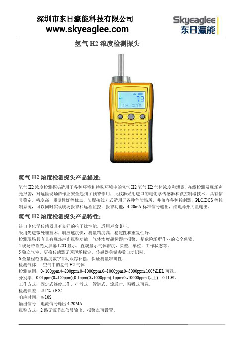
氢气H2浓度检测探头氢气H2浓度检测探头产品描述:氢气H2浓度检测探头适用于各种环境和特殊环境中的氢气H2氢气H2气体浓度和泄露,在线检测及现场声光报警,对危险现场的作业安全起到了预警作用,此仪器采用进口的电化学传感器和微控制器技术,具有信号稳定,精度高,重复性好等优点,防爆接线方式适用于各种危险场所,并兼容各种控制器,PLC,DCS等控制系统,可以同时实现现场报警和远程监控,报警功能,4-20mA标准信号输出,继电器开关量输出。
氢气H2浓度检测探头产品特性:进口电化学传感器具有良好的抗干扰性能,适用寿命8年。
采用先进微处理技术,响应速度快,测量精度高,稳定性和重复性好。
检测现场具有具有现场声光报警功能,气体浓度超标即时报警,是危险场所作业的安全保障。
4现场带背光大屏幕LCD显示,直观显示气体浓度,类型,单位,工作状态等。
5独立气室,更换传感器无须现场标定,传感器关键参数自动识别。
6全量程范围温度数字自动跟踪补偿,保证测量准确性。
检测气体:空气中的氢气H2气体检测范围:0~100ppm,0~200ppm,0~1000ppm,0~1000ppm,0~5000ppm,100%LEL可选。
分别率:0.01ppm(0~100ppm);0.1ppm(0~1000ppm);1ppm(0~10000ppm以上);0.1LEL.工作方式:固定式连续工作,扩散式,管道式,流通时,泵吸式可选。
检测误差:≦1%(F.S)响应时间:≦10S输出信号:电流信号输出4-20MA报警方式:2路无源节点信号输出,报警点可设置。
工作环境:-20℃~50℃(特殊要求:(-40℃~+70℃)相对湿度:≦90%RH工作电压:DC12~30V传感器寿命:3年防爆形式:探头变送器及传感器均为隔爆型。
防爆等级:Exd II CT6连接电缆:三芯电缆(单根线径≧1.5mm);建议选用屏蔽电缆。
连接距离:≦1000m.防护等级:IP65.外形尺寸:183X143X107mm.重量:1.5Kg.氢气H2浓度检测探头简单介绍:氢气H2浓度检测探头●自动温度补偿,零点,满量程漂移补偿●防高浓度气体冲击的自动保护功能●全软件校准功能,用户也可自行校准,用3个按键实现,操作简单●二线制4-20mA输出氢气H2浓度检测探头应用场所医药科研、制药生产车间、烟草公司、环境监测、学校科研、楼宇建设、消防报警、污水处理、工业气体过程控制石油石化、化工厂、冶炼厂、钢铁厂、煤炭厂、热电厂、、锅炉房、垃圾处理厂、隧道施工、输油管道、加气站、地下燃气管道检修、室内空气质量检测、危险场所安全防护、航空航天、军用设备监测等。
漫道科技冷凝气和氢气(H2)检测仪用户手册说明书
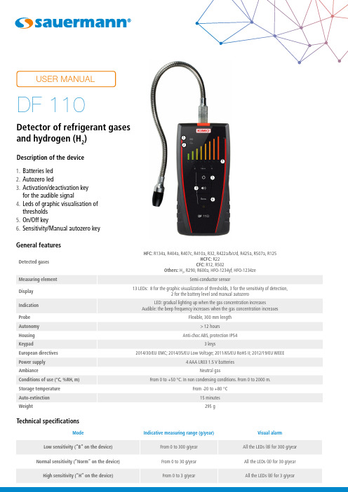
23456Detector of refrigerant gases and hydrogen (H 2)Description of the device1. Batteries led2. Autozero led3. Activation/deactivation keyfor the audible signal4. Leds of graphic visualisation of thresholds5. On/Off key6. Sensitivity/Manual autozero key DF 110Perform a measurement• Turn on the detector pressing the “On/Off” key.When it turns on, the pre-heating phase of the sensor begins. This phase lasts 60 seconds. During this phase, all the visualisation leds of thresholds light one after the other. A few second before the end of the pre-heating phase, all the leds blinks at the same time.Before using the device, make sure with the tester that the device works correctly (see next page).• Place the probe as close as possible to the site of the suspected leak.• Slowly move the probe (approximately 2 cm/second) in the direction to the possible source of the leak.It is important to move the probe past the leak and to go back toward it. The device responds to changes in gas concentration in the air. Moving the probe allows to the device to respond properly to these changes. If gas is detected, the frequency of the beep repetition will increase as the detected gas concentration increases and the leds of graphic visualisation lights from the left (low gas concentration) to the right (high gas concentration).Manual and automatic autozero functioningThe detector performs an automatic autozero every 2 s to set its minimum threshold of detection. This autozero allows to guarantee an optimum gas detection whatever the conditions of use (contaminated environment, temperature variations,...). In case of detection, according to the amplitude of gas measurement, the automatic autozero will deactivate to guarantee a better location of the leak. It will automatically reactivate after a return to normal conditions. In case of high gas concentration with a wide contaminated area, the automatic autozero can be not enough to detect precisely the location of the leak, there will be a measurement saturation. In this case, it is possible to perform a manual autozero into the contaminated area to reset the detection and to get back to a progressive sensitivity when getting close to the leak source.To perform a manual autozero, please see next page.Setting of the sensitivityIf the gas concentration is high, press “Sens” key to set the sensitivity and like this to get a better identification of the leak source. Please see next page for the details about the three different sensitivities.Adjust the deviceAdjust the sensitivity•Press the “Sensitivity/Autozero” key to adjust the sensitivity of the device.Activate/deactivate the audible signalBy default, when starting the device, the audible signal is always active.The device is turned on.• Press key to activate the audible signal.• Press this same key to deactivate it.Perform an autozeroThe device is turned on.• Press at least 3 s the key to perform an autozero.The “Autozero” led turns on.Perform a testThe DF 110 is supplied with a tester which allows to make sure that the detector works correctly.To test:• Remove the tester cap by pulling on it.• Turn on the detector and wait the end of the pre-heating phase (60 seconds).• Put the detection probe a few centimetres above the tester. The beep frequency increases and the leds of graphic visualisation must react and lights from the left to the right. This indicates that the sensor and theelectronic of the detector work correctly.After each test, remember to put the protective cap back on the tester.Replace the tester when its green colour is no longer visible.• Unscrew the probe tip.• Remove the filter located inside.• Put a new filter.• Screw the tip on the probe.Change the filter• Remove the front part at the back of the device.• Change the old batteries by AAA LR03 1.5V batteries.• Replace the front part.Change the batteriesN T _E N – D F 110 – 07/10/22 – N o n -c o n t r a c t u a l d o c u m e n t – W e r e s e r v e t h e r i g h t t o m o d i f y t h e c h a r a c t e r i s t i c s o f o u r p r o d u c t s w i t h o u t p r i o r n o t i c e .。
氢气H2泄露检测报警器

氢气H2泄露检测报警器氢气H2泄露检测报警器特点:★是款内置微型气体泵的安全便携装置★整机体积小,重量轻,防水,防爆,防震设计.★高精度,高分辨率,响应迅速快.★采用大容量可充电锂电池,可长时间连续工作.★数字LCD背光显示,声光、振动报警功能.★上、下限报警值可任意设定,自带零点和目标点校准功能,内置温度补偿,维护方便.★宽量程,最大数值可显示到50000ppm、100.00%Vol、100%LEL.★数据恢复功能,免去误操作引起的后顾之忧.★显示值放大倍数可以设置,重启恢复正常.★外壳采用特殊材质及工艺,不易磨损,易清洁,长时间使用光亮如新.氢气H2泄露检测报警器产品特性:★是款内置微型气体泵的高精度的手式安全便携装备;★进口电化学传感器具有良好的抗干扰性能,使用寿命长达3年;★采用先进微处理器技术,响应速度快,测量精度高,稳定性和重复性好;★检测现场具有现场声光报警功能,气体浓度超标即时报警,是危险现场作业的安全保障;★现场带背光大屏幕LCD显示,直观显示气体浓度/类型/单位/工作状态等;★全量程范围温度数字自动跟踪补偿,保证测量准确性;★半导体纳米工艺超低功耗32位微处量器;★全软件自动校准,传感器多达6级目标点校准功能,保证测量的准确性和线性,并且具有数据恢复功能;★全中文/英文操作菜单,简单实用,带温度补偿功能;★防高浓度气体冲击的自动保护功能;氢气H2泄露检测报警器技术参数:检测气体:空气中的氢气H2气体检测范围:0-100ppm、500ppm、1000ppm、5000ppm、0-100%LEL分辨率:0.1ppm、0.1%LEL显示方式:液晶显示温湿度:选配件,温度检测范围:-40~120℃,湿度检测范围:0-100%RH检测方式:扩散式、流通式、泵吸式可选安装方式:壁挂式、管道式检测精度:≤±3%线性误差:≤±1%响应时间:≤20秒(T90)零点漂移:≤±1%(F.S/年)恢复时间:≤20秒重复性:≤±1%信号输出:①4-20mA信号:标准的16位精度4-20mA输出芯片,传输距离1Km②RS485信号:采用标准MODBUS RTU协议,传输距离2Km③电压信号:0-5V、0-10V输出,可自行设置④脉冲信号:又称频率信号,频率范围可调(选配)⑤开关量信号:标配2组继电器,可选第三组继电器,继电器无源触点,容量220VAC3A/24VDC3A传输方式:①电缆传输:3芯、4芯电缆线,远距离传输(1-2公里)②GPRS传输:可内置GPRS模块,实时远程传输数据,不受距离限制(选配)接收设备:用户电脑、控制报警器、PLC、DCS、等报警方式:现场声光报警、外置报警器、远程控制器报警、电脑数据采集软件报警等报警设置:标准配置两级报警,可选三级报警;可设置报警方式:常规高低报警、区间控制报警电器接口:3/4″NPT内螺纹、1/2″NPT内螺纹,同时支持2种电器连接方式防爆标志:ExdII CT6(隔爆型)壳体材料:压铸铝+喷砂氧化/氟碳漆,防爆防腐蚀防护等级:IP66工作温度:-30~60℃工作电源:24VDC(12~30VDC)工作湿度:≤95%RH,无冷凝尺寸重量:183×143×107mm(L×W×H)1.5Kg(仪器净重)工作压力:0~100Kpa标准配件:说明书、合格证质保期:一年氢气H2泄露检测报警器简单介绍:氢气H2泄露检测报警器报警器高精度、高分辨率,响应快速,超大容量锂电充电电池,采样距离远,LCD 背光显示,声光报警功能,上、下限报警值可任意设定,可进行零点和任意目标点校准,操作简单,具有误操作数据恢复功能.氢气H2泄露检测报警器应用场所:医药科研、学校科研、制药生产车间、烟草公司、环境检测、楼宇建设、消防报警、污水处理、石油石化、化工厂、冶炼厂、钢铁厂、煤炭厂、热电厂、锅炉房、加气站、垃圾处理厂、隧道施工、输油管道、航空航天、工业气体过程控制、室内空气质量检测、地下燃气管道检修、危险场所安全防护、军用设备检测等。
氢气检测仪使用说明书山盾科技
山盾科技Multi Pro 600氢气检测仪用户使用手册v1.0.22014-2015 山盾科技(深圳)有限公司版权所有.该文档所包含的信息为山盾科技(深圳)有限公司专有。
该文档的第一接收人可以复制该文档的全部或部分内容供内部商业活动参考使用,该完整的通知需要出现在所有的副本中。
在复制该文档的任何内容时,使用者应该同意尽一切合理的努力去防止该文档内容在未经授权的情况下使用和传播。
阅读说明用户须知非常感谢您选择使用本公司的Multi Pro 600氢气检测仪(以下简称Multi Pro 600)。
在使用本产品前,请仔细阅读本用户手册。
本手册涵盖产品使用的各项重要信息及数据,用户必须严格遵守其规定,方可保证Multi Pro 600的正常运行。
同时,相关信息可帮助用户正确使用该产品,并获得准确的分析结果,节省由于咨询等服务产生的额外成本。
注意事项本手册介绍了Multi Pro 600的具体应用,以及如何启动、操作和维护。
需特别指出的是,本手册中的警告和安全信息至关重要,能有效地避免不恰当的操作。
本手册所述产品的开发、制造、测试都把适当的安全标准放在首位。
因此,如果用户按照本手册指导进行安装、核准使用和维护,可避免因操作不当而造成的常规使用中的财产损失和人身危害。
本手册内容仅供参考,如有变更,恕不另行通知!安全事项在打开仪器外壳前,必须切断电源。
切勿擅自或任意拆卸传感器。
请在符合仪器正常运行的环境条件下使用仪器。
在仪器安装和操作的过程中请严格遵守国家相关标准要求。
公司联系方式目录阅读说明 (1)用户须知 (1)注意事项 (1)安全事项 (1)公司联系方式 (1)1 简介 (4)1.1 产品概述 (4)1.2 产品特点 (4)2 技术参数 (5)3 仪器安装 (6)3.1 安装场所 (6)3.2 仪器结构尺寸 (7)3.3 安装说明 (7)3.4 电缆选择 (7)3.5 接线方式 (8)3.5.1 接线端子图解 (8)3.5.2 3线制4-20mA接线图 (10)3.5.3 4线制4-20mA接线图 (10)3.5.4 4线制RS485信号传输接线图 (11)3.5.5 2路4-20mA信号输出接线图 (11)3.6 报警继电器接线方式 (12)4 开始监测 (12)4.1 线路检查 (12)4.2 仪器监测状态 (13)4.2.1 仪器开机自检和预热状态 (13)4.2.2 正常监测状态 (13)4.2.3 一级报警状态 (14)4.2.4 二级报警状态 (14)5 仪器操作 (15)5.1 调零 (15)5.2 标定 (16)5.3 参数设置 (17)6 仪器维护 (17)6.1 传感器使用寿命 (17)6.2 传感器更换 (17)1简介1.1产品概述Multi Pro 600系列氢气检测仪可以24小时实时采集现场所测气体的浓度,并判断是否超过报警阈值,根据判断结果执行对应报警动作,同时将采集的数据和报警信息传送至气体报警控制器,能在各个工业领域起到在线监测和记录的作用。
KQ500点型气体探测器(汇总)

KQ500系列点型气体探测器产品概述:随着工业的迅速发展,人类接触有害气体的场合越来越多,由此造成对人类本身的危害也越来越大,一次次的中毒事故,使人们清醒的认识到在发展工业的同时保护人类自身安全的重要性。
因此各种有害气体报警仪渐渐成为工业安全生产中必不可少的防护设备。
KQ500系列点型气体探测器(以下简称探头),是我公司采用先进的电化学传感器,结合多年来从事气体检测探头研制的经验而开发出的新产品。
它可以广泛应用于冶金、石油、石化、化工、轻工、焦化、市政、煤气、制药、污水处理及许多特殊行业和领域。
可分别检测多种气体,如:可燃性气体和O2、H2S、CO、HCN、NO2、SO2、NH3、HCL、CL2、H2等十多种有毒气体。
仪器采用本安型电路设计,4~20mA标准信号两线制(可燃气为三线制)输出,可远距离传输,可直接进入DCS系统,探头具有灵敏度高、反应迅速、寿命长、极化时间短等特点,处于国内同类产品领先水平。
技术参数:检测气体:可燃气,有毒气体,氧气环境温度:有毒气体:-20℃~ + 50℃可燃气体:-40℃~ + 70 ℃环境湿度:≤90%R.H. (无冷凝)工作电压:24VDC±15%工作电流:KQ500-EX型为120mA,其它≤50 mA输出信号:4~20mA标准信号两线制输出(KQ500-EX型三线制)传感器: 电化学传感器; KQ500-EX型为催化燃烧式响应时间: T90小于30秒重量:1200g安装方式:壁挂式传输电缆:二芯屏蔽电缆(KQ500-EX型用三芯屏蔽电缆),截面2×1.5mm2,外径¢10mm 传输距离:≤1000m防爆等级:Exd IICT6(隔爆应用);ExiaIICT4(本安应用)防护等级: IP66产品信息表产品型号检测气体标准量程分辨率响应时间(T90)传感器预期寿命KQ500-O2氧气0-30%vol 0.1%vol ≤15秒2-3年KQ500-CO 一氧化碳0-1000ppm 1 ppm ≤15秒2-3年KQ500-H2S硫化氢0-100ppm 1 ppm ≤15秒2-3年KQ500-HCN 氢氰酸0-50ppm 0.1 ppm ≤30秒2-3年KQ500-CL2氯气0-20ppm 0.1 ppm ≤30秒2-3年KQ500-O3臭氧0-5ppm 0.01 ppm ≤25秒2-3年KQ500-NH3氨气0-200ppm 1 ppm ≤30秒2-3年KQ500-H2氢气0-1000ppm 1 ppm ≤30秒2-3年KQ500-NO2二氧化氮0-20ppm 0.1 ppm ≤25秒2-3年KQ500-PH3磷化氢0-20ppm 0.1 ppm ≤15秒2-3年KQ500-C3H3N 丙烯腈0-100ppm 1ppm ≤15秒2-3年KQ500-NO 一氧化氮0-250ppm 1ppm ≤25秒2-3年KQ500-HCL 氯化氢0-20ppm 0.1ppm ≤25秒2-3年二氧化硫0-20ppm 0.1ppm ≤15秒2-3年KQ500-SO2KQ500-EX 可燃气0-100%LEL 1%LEL ≤30秒3-5年未列气体种类和量程请与本公司联系KQ500点型气体探测器两线制接线示意图KQ500点型气体探测器三线制接线示意图。
H2氢气浓度传感器

H2氢气浓度传感器H2氢气浓度传感器特点:★整机体积小,重量轻★高精度,高分辨率,响应迅速快.★上、下限报警值可任意设定,自带零点和目标点校准功能,内置温度补偿,维护方便.★数据恢复功能,免去误操作引起的后顾之忧.★外壳采用特殊材质及工艺,不易磨损,易清洁,长时间使用光亮如新.H2氢气浓度传感器技术参数:★进口电化学传感器具有良好的抗干扰性能,使用寿命长达3年;★采用先进微处理器技术,响应速度快,测量精度高,稳定性和重复性好;★全量程范围温度数字自动跟踪补偿,保证测量准确性;★半导体纳米工艺超低功耗32位微处量器;★全软件自动校准,传感器多达6级目标点校准功能,保证测量的准确性和线性,并且具有数据恢复功能;★防高浓度气体冲击的自动保护功能H2氢气浓度传感器结构图:H2氢气浓度传感器接线示意图:H2氢气气体传感器参数工作电压DC5V±1%/DC24±1%波特率9600测量气体H2氢气气体检测原理电化学采样精度±2%F.S响应时间<30S重复性±1%F.S工作湿度10-95%RH,(无冷凝)工作温度-30~50℃长期漂移≤±1%(F.S/年)存储温度-40~70℃预热时间30S工作电流≤50mA工作气压86kpa-106kpa安装方式7脚拔插式质保期1年输出接口7pIN外壳材质铝合金使用寿命2年外型尺寸(引脚除外)33.5X31 21.5X31测量范围详见选型表输出信号TTL(标配)0.4-2.0VDC(常规)/4-20mA 数字信号格式数据位:8;停止位:1;校验位:无;传感器PIN脚定义图:传感器应用场所:医药科研、学校科研、制药生产车间、烟草公司、环境检测、楼宇建设、消防报警、污水处理、石油石化、化工厂、冶炼厂、钢铁厂、煤炭厂、热电厂、锅炉房、加气站、垃圾处理厂、隧道施工、输油管道、工业气体过程控制、室内空气质量检测、地下燃气管道检修、危险场所安全防护、设备检测等。
山特电池sbs-h2氢气检测器使用说明书

SBS-H2Hydrogen Gas Detector Kit For battery charging rooms and other areas where hydrogen gas may be present INSTALLATION, OPERATION & MAINTENANCEINSTRUCTIONSProtects Life, Property and ProfitsElectrical Safety – UL 61010-1Compliant with MFPA 70E® and IEEE RecommendationsPollution Degree 21-800-554-2243*******************Warnings∙This detector is added protection, not a substitute for prudent safety measures, for where hydrogen gas may be present.∙For large or highly-sensitive areas, SBS recommends installing additional sensors for increased coverage area.∙The hydrogen sensor does not provide protection from fires or hydrogen explosions.The relay contacts are intended to be connected to a safety system that would enable audible alarms, system shutdown and ventilation.∙Ensure that installation complies completely with all relevant Local, State, Federal and OSHA safety and health regulations.∙If a sensor enters warning or alarm mode there is a risk of combustion or explosion. To avoid injury, leave the area immediately.∙The sensor is calibrated for operation in air. Tampering with the sensor or operation in environments that are exposed to other types of gases can lead to inaccuratereadings, false alarms or permanent damage.∙Please see troubleshooting guide for list of gases and compounds that may damage or alter a sensor’s performance.∙Uncured silicone compounds or extended exposure to silicone off gassing can give inaccurate readings or false alarms on a sensor.Table of ContentsDescription Page SectionBenefits 5 2.0Specifications 6 4.0Main Control 7 6.0Operation 12 8.0Testing the Sensor 13 10.0Main Unit and Accessories Part No. DescriptionSBS-H2Hydrogen Gas DetectorIncludes: one (1) main control, one (1) H2-SENSOR and one (1) 25 ft. cableH2-JB Junction Box with Knockouts, 4 11/16" X 4 11/16", MetalH2-SENSOR Hydrogen Gas Sensor Only (No Cable)H2-SENSOR-25FT Additional/Replacement Hydrogen Gas Sensor with 25 ft. Cable H2-SENSOR-50FT Additional/Replacement Hydrogen Gas Sensor with 50 ft. Cable H2-SENSOR-100FT Additional/Replacement Hydrogen Gas Sensor with 100 ft. CableH2-TESTKIT Field Test Kit for SBS-H2Includes: case, regulator, tubing and two (2) cylinders of H2 gas (1% and 2%)H2-TESTKIT-INTL Field Test Kit for SBS-H2Includes: case, regulator and tubing – does not include H2 gas cylindersE190399110Vac 3 Prong AC Cord, 10 Ft., 18-3 AWG1.0 OverviewBatteries on charge emit hydrogen gas as part of the chemical reaction of recharge.Concentrations of 4.1% to 75% H2 mixed with air can be explosive. Sparks or hot surfaces can ignite hydrogen gas.The SBS-H2 hydrogen detector acts as a monitor and provides a visual and audible alarm when hydrogen is detected. The unit also has a 1% concentration relay that can trigger exhaust fan operation and a 2% concentration relay that can trigger a building management/alarm system (via SCADA/Modbus) before the gas reaches the lower explosive limit (LEL) of 4.1%.2.0 BenefitsIn addition to protecting employees and property, the detector may also reduce the following costs: Energy EfficienciesInstead of continuously running an exhaust fan to prevent hydrogen gas accumulation, use the detector to activate a fan only if the gas concentration reaches 1%.Insurance SavingsInstallation of a detector in areas where batteries are charged may result in a premium reduction.3.0 How it WorksShould the concentration of hydrogen gas in the air surrounding the sensor reach 1% by volume, the “1% Warning” yellow LED will light up on the main control of the unit. In addition, the 1% internal relay will energize and can be used to activate a remote exhaust fan.Should the hydrogen gas concentration reach 2% by volume, the “2% Alarm” red LED will light up, the strobe will flash and an audible alarm will sound. In addition, the 2% internal relay will energize and can be used to activate a building management/alarm system (via SCADA/Modbus).The SBS-H2 provides automatic operation, continuous detection, high sensitivity, stability and solid-state reliability. The unit uses 120/240 Vac 50/60 Hz and/or 12 - 48 Vdc operating voltages.4.0 SpecificationsDimensions∙Main control: 4.7" L x 4.7" W x 1.2" D∙Sensor: 3.1" L x 1.6" W x 0.87" DMounting∙Wall: two 3/16" screws (not included)∙H2-JB Junction box: 4 11/16" x 4 11/16" 2-gang junction boxPower Requirements/OptionsWarning: Power requirements for the unit and relays should not exceed min/max specifications ∙120 Vac, 50/60 Hz Nominal (Terminal J8)o93 - 121 Vaco250mA / 10W Max∙220 Vac, 50/60 Hz Nominal (Terminal J8)o185 - 242 Vaco125mA / 10W Max∙12-48 Vdc Nominal (Terminal J9)o9 - 58 Vdco600mA / 6W Maxo Note: An earth ground must be supplied to the GND terminal on the AC terminal block when using only the DC power supplyRelays∙1% Warning Relay (Terminal J6)o 1 Normally Open and 1 Normally Closed contacto Rated for 15 A resistive @ 120 Vaco Rated for 10 A resistive @ 277 Vaco Rated for 10 A resistive @ 28 Vdc∙2% Alarm Relay (Terminal J3)o 1 Normally Open and 1 Normally Closed contacto Rated for 0.5A @ 28 VdcTemperature/Humidity∙Operating Temperature Range: 32°F (0°C) to 122°F (50°C)∙Operating Humidity Range: 20-95% non-condensing∙Storage Humidity Range: 5-95% non-condensingMaximum Altitude∙2000 metersAudible Alarm∙85 dB at 10’ @ 1.6 - 3.2 KHzStrobe LED∙*******************.2V5.0 SensorThe H2-SENSOR consists of an electronic sensing element whose electrical conductivity increases when hydrogen is detected at its surface. Conductivity of the sensor is proportional to the gas concentration, which is continuously monitored by the electronic alarm circuits.The sensor only monitors for hydrogen gas (H 2) and will not alarm for Hydrogen Sulfide (H 2S), which has an odor at very low concentrations.6.0 Main ControlSensor HeadStrobe AlarmIndividual Sensor Indicators(For troubleshooting, refer to page 14.)Hydrogen SensorCat5 Cable(25 ft. std., 50/100 ft. optional)Main ControlMain Control Indicators (3 LEDs)7.0 InstallationWARNINGAC voltage relay terminals (120/240 Vac) are located within this detector, presenting a hazard toservice technicians. Only qualified technicians should open the detector case and service the internal circuits. Ensure power is removed from the detector relays prior to servicing the unit. Failure to do so may result in injury or death.Mounting and Power OptionsAlarm WiringH2-JB Junction Box Mountable (optional) Mounts to a standard, 4 11/16" x 4 11/16" 2-gang junction boxHardwire OptionRun AC and/or DC power and alarm wires through back of the unit, into the gang box and out through conduit.E190399 AC Line Cord3-prong grounded AC cord, 18-3 AWGWall MountableIntegrated back mounting plate allows user to easily mount directly to any wall using 3/16" screws (not included).WiringPower and alarm wires can run through the sides of the unit.Input PowerMounting LocationHydrogen is colorless and odorless; the lightest of all gases, and thus rises. The sensor should be installed at the highest, draft-free location in the battery room, cabinet or compartment where hydrogen gas would accumulate.The detector measures hydrogen gas concentration in the air immediately surrounding the sensor. The area one sensor will monitor depends on the properties of the battery compartment or room. Hydrogen gas may accumulate in several areas of the battery compartment or room and multiple sensors/detectors may be necessary.The main control can be mounted wherever is convenient for the user, but should be within the cable length range to connect to each sensor.The sensor should be mounted at the highest, draft-free location in the battery room, cabinet or compartment. Each sensor connects with the main control via the cable.Carefully remove the main control cover by removing the two screws located on the front of the cover. Attach the main control to the wall, ceiling or optional junction box using the mounting holes at the top and bottom of the main control’s mounting plate.After the power and relay wiring is complete, connect each cable from main control to each sensor and refasten the main control cover.Power OptionsThe detector has terminal blocks for connections to a single-phase 120/240 Vac 50/60 Hz power source (Terminal J8), and/or a 12-48 Vdc power source (Terminal J9). The power supply inputs are redundant, so the unit can use the DC input as a backup source.RelaysThe detector has two (2) internal alarm relays:∙1% warning relay (Terminal J6) is activated when a sensor detects 1% concentration of hydrogen gas. The 1% relay’s dry contacts are rated at 10A/250 Vac, sufficient for most 1/3HP exhaust fans.∙2% alarm relay (Terminal J3) is activated when a sensor detects 2% concentration of hydrogen gas. The 2% relay’s dry contacts are rated for 0.5A/28 Vdc.∙Note: For higher current requirements, add an external relay.Mounting OptionsJunction Box MountedFor 120/240 Vac power, use 18-3 gauge stranded wire.For 9 - 58 Vdc power, use 18-2 conductor insulated wire.For relay wires, use stranded wire. Maximum wire size for connector terminations is 14 AWG. Stranded conductors must be terminated in a manner to prevent shorting from one terminal to another by a loose strand. Tin the wires with solder if required.Wall MountedFor 120 Vac power, an 18-3 gauge insulated line cord is required.For 9 - 58 Vdc power, use 18-2 conductor insulated cable from the DC supply.For relay wires, use stranded wire. Maximum wire size for connector terminations is 14 AWG.Disconnection of Supplying PowerWhen the unit is hard wired, an external 10 Amp (minimum) circuit-breaker or switch should be installed to act as a disconnecting device. The circuit-breaker must open all supply conductors simultaneously, be easily reached by operators and be marked as the disconnecting device for the equipment.For Installation of Additional SensorsA maximum of three (3) sensors may be connected to each main control. Multiple detectors and sensors can be installed to meet the space coverage requirements of your particular installation.Locate the additional sensors ’ installation points within cable reach of the main control and mount the sensor. Connect the cables from any additional sensors to the Sensor 2 and Sensor 3 inputs on the main control.SBS supplies a tie-wrap to secure the AC mains ’ wiring. The tie wrap can rotate up to 270 degrees to accommodate your installation.Alarm System ElectronicsPlease refer to the illustration below to identify proper power and relay connection points in the detector. It is advisable to use a pair of 14 gauge or smaller stranded wire for the relay contacts to help reduce any interference within the area that may cause false alarms.Each of the Cat5 sensor input connections has a status indicator LED on the main control, which will illuminate solid green when a sensor is connected and operating normally. A sensor’s corresponding LED will flash at the same rate as the strobe LED when detecting 1% or 2% H2 concentration. The LED for a sensor that is in alarm mode will flash at the same rate as the strobe LED. The alarming sensor and strobe LED will flash at a faster rate than the LED for a sensor that is only in warning mode.Terminal Connection DiagramUsing the Mechanical Relays1. Remove the front cover of the main control by removing two fix screws and pulling straight offthe body. This will reveal the inner electronics of the alarm box.2. Locate the terminal blocks for the relays and determine which condition you would like therelay to be related to. Use the 1% relay (Terminal J6) for the warning condition and the 2% relay (Terminal J3) for the alarm condition.3. Replace the front cover on the alarm box.8.0 OperationKeep the detector on at all times. The solid green LED for ‘POWER’ on the main control indicates that the detector is powered on.When power is first turned on, a warm up period of 30 seconds will elapse before the unit will function. This delay is to prevent false activation of the internal relays and alarm.Should the concentration of hydrogen gas in the air surrounding the sensor reach 1% by volume, the “1% Warning ” yellow LED will light up on the main control of the unit. In addition, the 1% internal relay will energize and can be used to activate a remote exhaust fan.Should the hydrogen gas concentration reach 2% by volume, the “2% Alarm ” red LED will light up, the strobe will flash and an audible alarm will sound. In addition, the 2% internal relay will energize and can be used to activate a building management/alarm system (via SCADA/Modbus).Power Warning Alarm(sensor installed)(blinking green))(same flash rate as strobe)Warning and Alarm Relay Sensor/Cable Fault(plugged in, but not lit)Main Control IndicatorsIndividual Sensor Indicators9.0 Electrical TestingA "TEST" button is located on the front of the main control. Push and hold this button for approximately 10 seconds to test the unit's electronic circuitry.The warning and alarm LEDs will light up in sequence, the strobe will flash, the relays will activate whatever is connected to them and the internal warning alarm will sound.Note: The "TEST" button does NOT test the sensor(s) itself –only the unit’s electronic circuitry.10.0 Testing the SensorThe sensors and main controls are factory calibrated. It is recommended to test each sensor’s functionality every 12-18 months with the H2-TESTKIT.The H2-TESTKIT is intended for periodic testing of the functionality and proper operation of the system. Once a sensor is installed, calibration or adjustment of the sensor is not possible. Please contact your sales representative if sensor calibration is desired or required.The H2-TESTKIT includes the following:∙1% (17 liters) H₂ in air calibrated gas canister∙2% (17 liters) H₂ in air calibrated gas canister∙Regulator∙Flexible tubing with sensor head adapterTesting the 1% Warning and 2% Alarm State1. Connect the calibration fixture to the 1% H2 air gas cylinder.2. Secure the test fixture to the sensor module connected to sensor by pressing the flexible tubingcompletely over the inlet to the sensor head.3. Turn on the gas flow by slowly cracking the valve on the cylinder regulator until gas begins toflow. Please wait 30 seconds to ensure the air in the tubing has been purged.4. Continue gas flow and wait for the yellow LED warning to light up and the 1% relay to energize.5. Turn off gas and remove from sensor.6. Repeat Steps 1-5 above using the 2% H2 air gas cylinder to activate the 2% alarm and relay.The 2% alarm threshold is connected to the red LED, the audible alarm and the strobe light up, which will activate during testing.7. Repeat steps for every sensor installed.Note: If the unit does not alarm during these tests the sensor may need to be replaced.Replacing the SensorIn a typical operating environment SBS recommends that each sensor be replaced every three years. An abusive operating environment can and will shorten a unit’s useful life. In dusty/dirty applicationsor in situations where a sensor is often subjected to different gases, it is recommended to replace each sensor after one (1) year.11.0 Troubleshooting and MaintenanceNo PowerVerify the AC and/or DC power cables are installed per the connection diagram on page 11.RelaysThe SBS-H2 system was designed for the relays to operate in a failsafe condition when the power supply is interrupted. If the fan connected to a relay runs as soon as the unit is powered on, the unit has been wired for the use of the Normally Open contact instead of a Normally Closed contact.False AlarmsEach sensor has been calibrated for the detection of hydrogen gas, however any combustible gas that comes in contact with a sensor has the potential to activate the warning and/or alarm relays. Contact with any individual or combination of the following gases could trigger false alarms and/or contaminate a sensor.Gases include but are not limited to:-Acetone-Acetylene-Ammonia-Benzene-Butane-n-Butyl Acetate -Carbon Dioxide -Carbon Monoxide -Ethane-Ethanol-Ethyl Acetate -Ethyl Ether-Ethyl Oxide-Gasoline-Heptane-Hexane-Hydrogen-Hydrogen Cyanide-Hydrogen Sulfide-Isopropyl Alcohol-Methane-Methanol-Methyl Ethyl Ketone-Nitric Oxide-Nitric Dioxide-Propane-Propylene Oxide-Styrene-Sulfur Dioxide-Toluene-Turpentine-Vinyl Acetate-XyleneIf a sensor’s warning or alarm condition is reached, ventilate the area with clean air. This should reduce the concentration of most gases and the warning or alarm condition should clear.Note - when a warning occurs at 1%, the warning will not clear until concentrations drop below 0.5%. Similarly, when an alarm occurs at 2%, the alarm will not clear until concentrations drop below 1.5%.Avoid installation in highly corrosive environments where high densities of hydrogen sulfide, sulfur oxide, chlorine, hydrogen chloride, etc. may be present. These gases can cause corrosion of the element and the power leads to the circuit board.A sensor’s output characteristics can be affected if the sensor becomes contaminated or exposed to heavy alkaline metals.A sensor cannot operate in a zero or low oxygen content atmosphere.If a sensor collects water condensation, its characteristics may temporarily drift. However, light levels of condensation under normal indoor use should not pose a significant problem with performance. StorageThe longer a sensor is stored prior to being energized, the longer the warm up and stabilization period may become. Storage Humidity Range: 5 - 95% non-condensing.Maintenance TipsTo maintain the unit, it is recommended to:1. Test the detector once a month by pressing the ‘TEST’ button.2. Vacuum the alarm cover once a month to remove accumulated dust.3. Never use detergents or solvents to clean the unit or sensor. Chemicals can permanentlydamage or temporarily contaminate a sensor.4. Avoid spraying air fresheners, hair spray, paint or other aerosols near a sensor.5. Never paint the unit or sensor. Paint will seal the vents and interfere with proper sensoroperation.WARNINGSDo not disassemble unit or attempt to repair or modify any component of this instrument. This instrument contains no user serviceable parts, and substitution of components may impair intrinsic safety, which may adversely affect product performance and result in injuryThe SBS-H2 Hydrogen Alarm System is not a standalone safety device and does not provide protection from hydrogen explosions. The relay contacts are intended to be connected to a safety system, enabling audible alarms, system shutdown, ventilation, or other measures to ensure monitoring of hydrogen gas occurs before concentrations reach dangerous levels.The information in this sheet has been carefully reviewed and is believed to be accurate; however, no responsibility is assumed for inaccuracies. Storage Battery Systems, LLC reserves the right to make changes without further notice to any product, datasheet, technical data bulletin, or website.Storage Battery Systems, LLC makes no warranty, representation of guarantee regarding the suitability of its product for any particular purpose, nor does Storage Battery Systems, LLC assume any liability arising out of the application or use of any product and specifically disclaims any and all liability, including without limitation consequential or incidental damages. “Typical” parameters can and do v ary in different applications. All operating parameters, including “Typical” must be validated for each customer application by customer’s technical experts.Storage Battery Systems, LLC products are not designed, intended, or authorized for use in any application in which the failure of the SBS product could create a situation where personal injury or death may occur.Should buyer purchase or use SBS products for any such unintended or unauthorized application, Buyer shall indemnify and hold Storage Battery Systems, LLC and its officers, employees, subsidiaries, affiliates, and distributors harmless against all claims, costs, damages, and expenses, and reasonable attorney fees arising out of, directly or indirectly, any claim of personal injury or death associated with such unintended or unauthorized use, even if claim alleges that Storage Battery Systems, LLC was negligent regarding the design or manufacture of the part.In the case of a defect in the sensor, Storage Battery Systems, LLC shall not be liable for any damages which may result, including, but not limited to, loss of revenue, property, or life. In an event, Storage Battery Systems, LLC shall limit liability to replacement of the defective unit. Storage Battery Systems, LLC does not convey any license under its patent rights nor the rights of others.。
北京东方吉华 固定式氢气检测仪 说明书
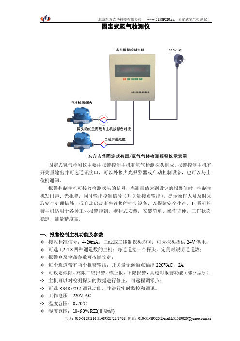
气检测仪固定式氢固定式氢气检测仪固定式氢气检测仪主要由报警控制主机和氢气检测探头组成。
报警控制主机有开关量输出并可选通讯接口,可以外接声光报警器或启动控制设备,也可以与上位机通讯。
报警控制主机可接收检测探头的信号,当测量值达到设定的报警值时,控制主机发出声、光报警,同时输出控制信号(开关量接点输出),提示操作人员及时采取安全处理措施,或自动启动事先连接的控制设备,以保障安全生产。
Jh系列报警主机适用于各种工业报警控制,壁挂式安装,安装简单、操作方便,工作状态稳定、测量精度高。
一、报警控制主机功能及参数�接收标准信号:4-20mA,二线或三线制探头均可,可为探头提供24V供电;�可选1,2,4,8四种通道数的主机:每通道接一个探头,定货时说明通道数;�报警点及全部参数可按键设定;�每个通道带有两个报警输出;开关量无源触点输出220V AC,2A�可设定低限、高限二级报警,或上限、下限报警,具延时报警功能(部分型号);�主机可以对检测探头的数据进行修正,可远程调零点;�可选RS485/232通讯功能,并进行实时监控和通讯。
�工作电压220V AC�温度范围:0~70℃�湿度范围:10~90%RH(非凝结)�精度:0.2%F.s (单通道为:0.5%F.s )�安装方式:壁挂式安装�重量:约1.2kg (单/双通道)�外形尺寸:200X200X80mm 二、氢气探头功能参数三、使用说明将氢气检测探头安装于需要监测的地点,可以多点监控,通过二芯屏蔽电缆接入主机,接线时按说明书或示意图中说明,按颜色对接即可。
主机安装于中控室等安全场合,根据需要安装声光报警器、排风扇等设备。
当氢气浓度超出预设报警点时,系统发出声光报警,同时启动排风扇等设备。
一般在设备出厂时,量程、报警点等全部参数都已经按用户要求或相关标准设置完毕,用户在固定和接线之后,即可通电测试。
注:1、现场可配带数字显示的氢气检测探头或进口的氢气检测探头。
- 1、下载文档前请自行甄别文档内容的完整性,平台不提供额外的编辑、内容补充、找答案等附加服务。
- 2、"仅部分预览"的文档,不可在线预览部分如存在完整性等问题,可反馈申请退款(可完整预览的文档不适用该条件!)。
- 3、如文档侵犯您的权益,请联系客服反馈,我们会尽快为您处理(人工客服工作时间:9:00-18:30)。
H2气体探测器
H2气体探测器特点:
★是款内置微型气体泵的安全便携装置
★整机体积小,重量轻,防水,防爆,防震设计.
★高精度,高分辨率,响应迅速快.
★采用大容量可充电锂电池,可长时间连续工作.
★数字LCD背光显示,声光、振动报警功能.
★上、下限报警值可任意设定,自带零点和目标点校准功能,内置
温度补偿,维护方便.
★宽量程,最大数值可显示到50000ppm、100.00%Vol、100%LEL.
★数据恢复功能,免去误操作引起的后顾之忧.
★显示值放大倍数可以设置,重启恢复正常.
★外壳采用特殊材质及工艺,不易磨损,易清洁,长时间使用光亮如新.
H2气体探测器产品特性:
★是款内置微型气体泵的高精度的手式安全便携装备;
★进口电化学传感器具有良好的抗干扰性能,使用寿命长达3年;
★采用先进微处理器技术,响应速度快,测量精度高,稳定性和重复性好;
★检测现场具有现场声光报警功能,气体浓度超标即时报警,是危险现场作业的安全保障;
★现场带背光大屏幕LCD显示,直观显示气体浓度/类型/单位/工作状态等;
★全量程范围温度数字自动跟踪补偿,保证测量准确性;
★半导体纳米工艺超低功耗32位微处量器;
★全软件自动校准,传感器多达6级目标点校准功能,保证测量的准确性和线性,并且具有数据恢复功能;★全中文/英文操作菜单,简单实用,带温度补偿功能;
★防高浓度气体冲击的自动保护功能;
H2气体探测器技术参数:
检测气体:空气中的H2气体
检测范围:0-100ppm、500ppm、1000ppm、5000ppm、0-100%LEL
分辨率:0.1ppm、0.1%LEL
显示方式:液晶显示
温湿度:选配件,温度检测范围:-40~120℃,湿度检测范围:0-100%RH
检测方式:扩散式、流通式、泵吸式可选安装方式:壁挂式、管道式检测精度:≤±3%线性误差:≤±1%
响应时间:≤20秒(T90)零点漂移:≤±1%(F.S/年)恢复时间:≤20秒重复性:≤±1%
信号输出:①4-20mA信号:标准的16位精度4-20mA输出芯片,传输距离1Km
②RS485信号:采用标准MODBUS RTU协议,传输距离2Km
③电压信号:0-5V、0-10V输出,可自行设置
④脉冲信号:又称频率信号,频率范围可调(选配)
⑤开关量信号:标配2组继电器,可选第三组继电器,继电器无源触点,容量220VAC3A/24VDC3A
传输方式:①电缆传输:3芯、4芯电缆线,远距离传输(1-2公里)
②GPRS传输:可内置GPRS模块,实时远程传输数据,不受距离限制(选配)
接收设备:用户电脑、控制报警器、PLC、DCS、等
报警方式:现场声光报警、外置报警器、远程控制器报警、电脑数据采集软件报警等
报警设置:标准配置两级报警,可选三级报警;可设置报警方式:常规高低报警、区间控制报警
电器接口:3/4″NPT内螺纹、1/2″NPT内螺纹,同时支持2种电器连接方式
防爆标志:ExdII CT6(隔爆型)壳体材料:压铸铝+喷砂氧化/氟碳漆,防爆防腐蚀
防护等级:IP66工作温度:-30~60℃
工作电源:24VDC(12~30VDC)工作湿度:≤95%RH,无冷凝
尺寸重量:183×143×107mm(L×W×H)1.5Kg(仪
器净重)
工作压力:0~100Kpa
标准配件:说明书、合格证质保期:一年
H2气体探测器简单介绍:
H2气体探测器报警器高精度、高分辨率,响应快速,超大容量锂电充电电池,采样距离远,LCD背光显示,声光报警功能,上、下限报警值可任意设定,可进行零点和任意目标点校准,操作简单,具
有误操作数据恢复功能.
H2气体探测器应用场所:
医药科研、学校科研、制药生产车间、烟草公司、环境检测、楼宇建设、消防报警、污水处理、石油石化、化工厂、冶炼厂、钢铁厂、煤炭厂、热电厂、锅炉房、加气站、垃圾处理厂、隧道施工、输油管道、航空航天、工业气体过程控制、室内空气质量检测、地下燃气管道检修、危险场所安全防护、军用设备检测等。