
SCT155K601A3B25-F中文资料
略图
上视图
Front View
Top View
��� L ±1.0 mm 9.0 mm .35 in ������16.0 mm 0.63 in both ends
H for "S" Type (in) 0.87 0.87 0.87 0.87 0.98 1.18 1.38 0.87 0.87 0.87 0.87 0.98 1.18 (mm) 22.0 22.0 22.0 22.0 25.0 30.0 35.0 22.0 22.0 22.0 22.0 25.0 30.0
1000 Vdc SCT224K102D3B25-F 0.22 SCT474K102D3B25-F 0.47 SCT564K102D3B25-F 0.56 SCT684K102D3B25-F 0.68 SCT105K102D3B25-F 1.00 SCT125K102D3B25-F 1.20
������������������������������������������������������������������������������������������������������������������������������������
Cap. 60 Hz dV/dt (µF) (Vac) (V/µs) 275 275 275 275 275 275 275 500 500 500 500 500 500 250 200 150 150 150 150 120 650 450 400 400 400 400
Ipk (A) 118 136 150 225 300 495 564 143 211 224 272 400 480
������������������ Film�����������
Part Numbering System
SCT 105 K 122
电压代码 型号体系
SCT型
IGBT突波吸收盒装电容器A3B端口安装型状25
端口洞孔距离
—F Compliant Designation F = Compliant Blank = Not
特点:
Highlights
承受瞬间大电流
dV/dt is encountered. Connect these capacitors from C1 to E2 on a dual IGBT module or from terminal P
N端口除去了在六组模块上一些瞬间的电压。
连接在两个IGBT模块上联络C1到E2的电容器,或者从P端口及
W for "S" Type (in) 1.30 1.30 1.30 1.30 1.42 1.57 1.77 1.30 1.30 1.30 1.30 1.42 1.57 (mm) 33.0 33.0 33.0 33.0 36.0 40.0 45.0 33.0 33.0 33.0 33.0 36.0 40.0
� � � �
种类
���������������������������������� ����������������������������������
小于20nH的低电感 直接安装在IGBT模块上
to terminal N on a six-pack module to eliminate severe voltage transients.
SCT224K122D3B25-F SCT334K122D3B25-F SCT474K122D3B25-F SCT684K122D3B25-F SCT105K122D3B25-F SCT155K122D3B25-F SCT205K122D3B25-F SCT305K122D3B25-F SCT224K162D3B25-F SCT334K162D3B25-F SCT474K162D3B25-F SCT684K162D3B25-F SCT105K162D3B25-F SCT155K162D3B25-F SCT205K162D3B25-F SCT224K202D3B25-F SCT334K202D3B25-F SCT474K202D3B25-F SCT684K202D3B25-F SCT105K202D3B25-F SCT125K202D3B25-F SCT155K202D3B25-F
CDE Cornell Dubilier • 1605 E. Rodney French Blvd. • New Bedford, MA 02744 • Phone: (508)996-8561 • Fax: (508)996-3830 •
元器件交易网
0.22 0.33 0.47 0.68 1.00 1.50 2.00 3.00 0.22 0.33 0.47 0.68 1.00 1.50 2.00 0.22 0.33 0.47 0.68 1.00 1.20 1.50
550 550 550 550 550 550 550 550 630 630 630 630 630 630 630 630 630 630 630 630 630 630
环保设计
内部使用
RoHS
Type SCT
型号
Value
电容值
Tolerance
电容误差
Voltage Code
Internal Use Only A D 3 3
Terminal
Terminal
Mounting B S SL See Outline Drawings
Hole Spacing 23 = 23 mm 25 = 25 mm 28 = 28 mm (For B & S Styles Only)
S型的高度
ESR
Cap. 60 Hz dV/dt Ipk Typ. 100 kHz (µF) (Vac) (V/µs) (A) (mΩ) (Arms) 1200 Vdc
W for "S" Type (in) 1.30 1.30 1.42 1.57 1.57 1.77 1.77 2.17 1.30 1.30 1.42 1.57 1.77 2.17 2.17 1.30 1.42 1.57 1.77 1.85 2.17 2.17 (mm) 33.0 33.0 36.0 40.0 40.0 45.0 45.0 55.0 33.0 33.0 36.0 40.0 45.0 55.0 55.0 33.0 36.0 40.0 45.0 47.0 55.0 55.0
650 500 500 500 500 400 400
143 165 235 340 500 600 800
19 13 10 7 5 4 4 5 19 12 10 7 6 5 5 19 13 10 8 6 5 5
6.4 7.8 9.8 12.7 15.1 19.6 19.6 20.0
400 1200 650 650 650 650 500 400 400 800 800 800 600 600 600 600 143 215 306 442 500 600 800 176 264 376 408 600 720 900
474 = .47 µF K = ±10% 601 = 600 Vdc 105 = 1.0 µF 102 = 1000 Vdc 122 = 1200 Vdc 162 = 1600Vdc 202 = 2000 Vdc
Outline Drawings
前视图 SCT B型端子型状 ��� W ±1.0 mm ������H ±1.0 mm �18.27 mm .719 in
目录型号
Catalog Part Number
电容量
頻率
电压 上升 速率
70°C
Length (L) (in) 1.77 1.77 1.77 1.77 2.01 2.01 2.32 1.77 1.77 1.77 1.77 2.01 2.01 (mm) 45.0 45.0 45.0 45.0 51.0 51.0 59.0 45.0 45.0 45.0 45.0 51.0 51.0
����������������������
符合UL94V0 标准的阻燃环氧树脂封装
���������������������������������������������
RoHS Compliant
Ratings
安培
I
等效 串联 电阻 峰值 电流
SL型尺寸的参考因素 Consult Factory for "SL" Style Dimensions 长度 B型的高度 B型的宽度
H for "B" Type
S型的宽度
W for "B" Type H for "S" Type (in) 0.87 0.87 0.98 1.18 1.18 1.38 1.38 1.77 0.87 0.87 0.98 1.18 1.38 1.77 1.77 0.87 0.98 1.18 1.38 1.54 1.77 1.77 (mm) 22.0 22.0 25.0 30.0 30.0 35.0 35.0 45.0 22.0 22.0 25.0 30.0 35.0 45.0 45.0 22.0 25.0 30.0 35.0 39.0 45.0 45.0
1600 Vdc 6.4 8.1 9.8 12.7 15.9 20.0 20.0 2000 Vdc 6.4 8.2 10.7 13.8 16.6 20.0 20.0
Note: Other capacitance values, voltages, lug orientations and terminal hole spacings are available. Please contact us.
SCT474K601A3B25-F SCT684K601A3B25-F SCT105K601A3B25-F SCT155K601A3B25-F SCT205K601A3B25-F SCT335K601A3B25-F SCT475K601A3B25-F
2级能效 挂壁机 苏宁专供 规格参数

挂壁机苏宁专供规格参数系列苏宁集团专供系列苏宁集团专供系列苏宁集团专供系列苏宁集团专供系列苏宁集团专供系列苏宁集团专供系列苏宁集团专供系列苏宁集团专供系列HP(匹数) 1HP 1HP 1HP 1HP 1.5HP 1.5HP 1.5HP 1.5HP型号室内机FTXS225NCSXFTXS225NCSSFTXS225NCSRFTXS225NCSWFTZS235NCSXFTZS235NCSSFTZS235NCSRFTZS235NCSW室外机RXS225NCSRXS225NCSRXS225NCSRXS225NCSRZS235NCSRZS235NCSRZS235NCSRZS235NCS遥控器ARC466A4 ARC466A4 ARC466A4 ARC466A4 ARC466A4 ARC466A4 ARC466A4 ARC466A4适用面积*1 制冷/制热㎡10~16/8~1510~16/8~1510~16/8~1510~16/8~1514~19/10~1714~19/10~1714~19/10~1714~19/10~17电源单相220V50Hz单相220V50Hz单相220V50Hz单相220V50Hz单相220V50Hz单相220V50Hz单相220V50Hz单相220V50Hz制冷量(min-max) kW2.5(1.3~3.2)2.5(1.3~3.2)2.5(1.3~3.2)2.5(1.3~3.2)3.5(1.25~4.0)3.5(1.25~4.0)3.5(1.25~4.0)3.5(1.25~4.0)制热量(min-max) kW3.4(1.3~4.8)3.4(1.3~4.8)3.4(1.3~4.8)3.4(1.3~4.8)4.2(1.4~5.6)4.2(1.4~5.6)4.2(1.4~5.6)4.2(1.4~5.6)APF(全年能源消耗效率)*2 W·h/(W·h)4.26 4.26 4.26 4.26 4.14 4.14 4.14 4.14尺寸(H×W×D) 室内机㎜283×868×21283×868×21283×868×21283×868×21283×868×21283×868×21283×868×21283×868×21室外机㎜550×658×275550×658×275550×658×275550×658×275550×765×305550×765×305550×765×305550×765×305重量室内机/室外机kg 9/31 9/31 9/31 9/31 9/35 9/35 9/35 9/35 *1 适用面积会因房间所在地区、结构、朝向等实际情况有所不同*2 APF依据国家能效标准GB21455-2013的测试方法得出系列苏宁集团专供系列苏宁集团专供系列苏宁集团专供系列苏宁集团专供系列苏宁集团专供系列苏宁集团专供系列苏宁集团专供系列苏宁集团专供系列苏宁集团专供系列苏宁集团专供系列苏宁集团专供系列苏宁集团专供系列HP(匹数) 1HP 1HP 1HP 1HP 1.5HP 1.5HP 1.5HP 1.5HP 1.5HP 1.5HP 1.5HP 1.5HP型号室内机FTXS225KCSS5FTXS225KCSX5FTXS225KCSR5FTXS225KCSW5FTXS235KCSS5FTXS235KCSX5FTXS235KCSR5FTXS235KCSW5FTZS235KCSS5FTZS235KCSX5FTZS235KCSR5FTZS235KCSW5室外机RXS225KCS5RXS225KCS5RXS225KCS5RXS225KCS5RXS235KCS5RXS235KCS5RXS235KCS5RXS235KCS5RZS235KCS5RZS235KCS5RZS235KCS5RZS235KCS5 遥控器ARC466A4ARC466A4ARC466A4ARC466A4ARC466A4ARC466A4ARC466A4ARC466A4ARC466A4ARC466A4ARC466A4ARC466A4适用面积*1 制冷/制热㎡10~16/8~1510~16/8~1510~16/8~1510~16/8~1514~19/10~1714~19/10~1714~19/10~1714~19/10~1714~20/10~1814~20/10~1814~20/10~1814~20/10~18电源单相220V50Hz单相220V50Hz单相220V50Hz单相220V50Hz单相220V50Hz单相220V50Hz单相220V50Hz单相220V50Hz单相220V50Hz单相220V50Hz单相220V50Hz单相220V50Hz制冷量(min-max) kW2.5(1.3~3.2)2.5(1.3~3.2)2.5(1.3~3.2)2.5(1.3~3.2)3.5(1.3~3.8)3.5(1.3~3.8)3.5(1.3~3.8)3.5(1.3~3.8)3.5(1.4~4.0)3.5(1.4~4.0)3.5(1.4~4.0)3.5(1.4~4.0)制热量(min-max) kW3.4(1.3~4.4)3.4(1.3~4.4)3.4(1.3~4.4)3.4(1.3~4.4)4.2(1.3~5.0)4.2(1.3~5.0)4.2(1.3~5.0)4.2(1.3~5.0)4.2(1.4~5.5)4.2(1.4~5.5)4.2(1.4~5.5)4.2(1.4~5.5)SEER(制冷季节能效比)*25.22 5.22 5.22 5.22 5.48 5.48 5.48 5.48 5.63 5.63 5.63 5.63 SEER(制冷季节能效比)*34.86 4.86 4.86 4.86 4.53 4.53 4.53 4.53 4.83 4.83 4.83 4.83 尺寸(H×W 室内机㎜283×868×210283×868×210283×868×210283×868×210283×868×210283×868×210283×868×210283×868×210283×868×210283×868×210283×868×210283×868×210×D)室外机㎜550×658×275 550×658×275550×658×275550×658×275550×658×275550×658×275550×658×275550×658×275550×765×285550×765×285550×765×285550×765×285重量室内机/室外机kg9/31 9/31 9/31 9/31 9/31 9/31 9/31 9/31 9/34 9/34 9/34 9/34*1 适用面积会因房间所在地区、结构、朝向等实际情况有所不同*2 SEER值依据国家生产标准GB7725-2004的测试方法得出*3 SEER值依据国家能效标准GB21455-2008的测试方法得出系列苏宁集团专供系列苏宁集团专供系列苏宁集团专供系列苏宁集团专供系列苏宁集团专供系列苏宁集团专供系列苏宁集团专供系列苏宁集团专供系列苏宁集团专供系列苏宁集团专供系列苏宁集团专供系列苏宁集团专供系列HP(匹数) 1HP 1HP 1HP 1HP 1.5HP 1.5HP 1.5HP 1.5HP 1.5HP 1.5HP 1.5HP 1.5HP型号室内机FTXS225KCSSFTXS225KCSXFTXS225KCSRFTXS225KCSWFTXS235KCSSFTXS235KCSXFTXS235KCSRFTXS235KCSWFTZS235KCSSFTZS235KCSXFTZS235KCSRFTZS235KCSW 室外机RXS225KCSRXS225KCSRXS225KCSRXS225KCSRXS235KCSRXS235KCSRXS235KCSRXS235KCSRZS235KCSRZS235KCSRZS235KCSRZS235KCS 遥控器ARC46ARC46ARC46ARC46ARC46ARC46ARC46ARC46ARC46ARC46ARC46ARC466A4 6A4 6A4 6A4 6A4 6A4 6A4 6A4 6A4 6A4 6A4 6A4适用面积*1制冷/制热㎡10~16/8~1510~16/8~1510~16/8~1510~16/8~1514~19/10~1714~19/10~1714~19/10~1714~19/10~1714~20/10~1814~20/10~1814~20/10~1814~20/10~18 电源单相220V50Hz单相220V50Hz单相220V50Hz单相220V50Hz单相220V50Hz单相220V50Hz单相220V50Hz单相220V50Hz单相220V50Hz单相220V50Hz单相220V50Hz单相220V50Hz制冷量(min-max)kW2.5(1.3~3.2)2.5(1.3~3.2)2.5(1.3~3.2)2.5(1.3~3.2)3.5(1.3~3.8)3.5(1.3~3.8)3.5(1.3~3.8)3.5(1.3~3.8)3.5(1.4~4.0)3.5(1.4~4.0)3.5(1.4~4.0)3.5(1.4~4.0)制热量(min-max)kW3.4(1.3~4.4)3.4(1.3~4.4)3.4(1.3~4.4)3.4(1.3~4.4)4.2(1.3~5.0)4.2(1.3~5.0)4.2(1.3~5.0)4.2(1.3~5.0)4.2(1.4~5.5)4.2(1.4~5.5)4.2(1.4~5.5)4.2(1.4~5.5)SEER(季节能效比)*25.22 5.22 5.22 5.22 5.48 5.48 5.48 5.48 5.63 5.63 5.63 5.63SEER(季节能效比)*34.86 4.86 4.86 4.86 4.53 4.53 4.53 4.53 4.83 4.83 4.83 4.83尺寸(H×W ×D) 室内机㎜283×868×210283×868×210283×868×210283×868×210283×868×210283×868×210283×868×210283×868×210283×868×210283×868×210283×868×210283×868×210 室外机㎜550×65550×65550×65550×65550×65550×65550×65550×65550×76550×76550×76550×768×275 8×275 8×275 8×275 8×275 8×275 8×275 8×275 5×285 5×285 5×285 5×285重量室内机/室外机kg9/31 9/31 9/31 9/31 9/31 9/31 9/31 9/31 9/34 9/34 9/34 9/34*1 适用面积会因房间所在地区、结构、朝向等实际情况有所不同*2 SEER值依据国家生产标准GB7725-2004的测试方法得出*3 SEER值依据国家能效标准GB21455-2008的测试方法得出。
负温度系数热敏电阻器:SCK 系列

16
2.5
0.471
√√√√√
SCK10202□
20
2
0.646
√√√√√
SCK10222□
22
2
0.659
√√
√√
SCK10252□
25
2
0.674
√√√√√
SCK10302□
30
SCK10472□
47
2
0.700
2
0.720
√√√√√ √√√√√
SCK10502□
50
2
0.813
√√√√√
SCK10801□
UL
安规认证 cUL CSA TUV CQC
熔断器型号

熔断器型号
1.XRNT快速熔断器,主要特点有:
分断能力高,开断电流可达63千伏。
功耗小、升温低。
动作特别快,安一秒特性要比国内目前生产的同类产品动作快,例如额定电流100安的熔断体,通以1000安预期电流,弧前时间不超0.1S。
安秒特性误差小于±10%。
配有弹簧式撞击器,该撞击器具有接触面大,压强力小的特点,因此,在推动开关联动锁动作时,不会产生将开关与撞针接触面打碎或击穿的情况发生。
2.RT14-20快速熔断器:
此型号的快速熔断器是由熔断体和熔断器底座二部分组成的,熔断体由纯铜片制成的变截面熔体封装于由高强度瓷制成的熔管内,熔管中充满经化学处理过的高纯度石英砂作为灭弧介质,熔体二端与端帽牢固电连接,且熔丝的两面都与铜冒接触,俗称双盖,组成圆筒帽形结构。
熔断器底座由树脂或塑料压制的外壳装上触头和载熔件后,或经铆合连接而成。
3.SP10M10快速熔断器具有以下特点:
SP10M10快速熔断器的工作温度范围非常大,上限可以达到90℃,下限可以达到-50℃。
具有良好的分断能力,最大分断能力达到35千安,分断时间常数为1-3毫秒。
熔断特性优越:SP系列直流熔断器在实际工作电流达到额定电流的1.13倍时,1小时内熔断;当实际电流达到额定电流的1.45倍时,在一个小时内熔断。
该特性,特别适用于光伏电站电池板输出电流不断变化的要求。
15立方移动压风机技术参数
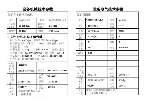
标准
编号
MT687-1997
重量
3460 kg
出厂
编号
050307#
出厂
日期
2005.2
生产
厂家
济南压缩机有限公司
(济南.平阴)
设备电气技术参数
煤矿用隔爆
型号
YBK2-315M-6
功率
90 KW
电压
380/660 V
接线
方式
△/Y
电流
167/96.4 A
频率
50Hz
噪声
LW
85 dB(A)
绝缘
等级
F
工作
定额
S1
相数
3
防护
等级
IP55
转速
989 r/min
COS¢
0.88
生产
许可证
外尺寸
防爆
合格证
2042141
安全
标志
20041417
标准
编号
JB/T9593.1-2007
重量
928 kg
出厂
编号
0003#
出厂
日期
2005.2
生产
厂家
山东三防防爆电机有限公司
(山东防爆电机厂)
产品类型:一类
容器净重:270 kg容积:0.6m3介质:空气
生产许可证:RZZ鲁-109-2006出厂日期:2005.3
产品编号:05K15003产品标准:GB150-1998
生产厂家:济南压缩机有限公司
矿用检验证
K20305
生产
许可证
XK06-110-00104
外尺寸
2930×1370×1562mm
HT1628中文资料

LED驱动控制专用电路---HT1628一、概述HT1628是一种带键盘扫描接口的LED(发光二极管显示器)驱动控制专用电路,内部集成有MCU数字接口、数据锁存器、LED高压驱动、键盘扫描等电路。
本产品性能优良,质量可靠。
二、特性说明�采用功率CMOS工艺�多种显示模式(10段×7位~13段×4位)�键扫描(10×2bit)�辉度调节电路(占空比8级可调)�串行接口(CLK,STB,DI/O)�振荡方式:RC振荡�内置上电复位电路�封装形式:SOP28三、内部功能框图:四、管脚定义:管脚功能定义:五、显示寄存器地址和显示模式:该寄存器存储通过串行接口从外部器件传送到HT1628的数据,地址分配如下:六、键扫描和键扫数据寄存器:为10×3bit,如下所示:键扫数据储存地址如下所示,用读指令读取,读从低位开始:七、指令说明:指令用来设置显示模式和LED驱动器的状态。
在STB下降沿后由DIN输入的第一个字节作为一条指令。
如果在指令或数据传输时STB被置为高电平,串行通讯被初始化,并且正在传送的指令或数据无效(之前传送的指令或数据保持有效)。
(1)显示模式设置:该指令用来设置选择段和位的个数(4~7位,10~13段)。
当指令执行时,显示被强制终止,同时键扫描也停止。
要重新显示,显示开/关指令“ON”必需被执行,但当相同模式被设置时,则上述情况并不发生。
上电时,设置模式为4位,14段。
(2)数据设置:该指令用来设置数据写和读(3)地址设定:该指令用来设置显示寄存器的地址。
如果地址设为0EH或更高,数据被忽略,直到有效地址被设定。
上电时,地址设为00H。
(4)显示控制:上电时,设置为脉冲宽度为1/16,显示关。
上电时,键扫停止。
八、串行数据传输格式:数据接收(写数据)数据读取:因为DOUT管脚为N管开漏输出,所以该脚要连接一个外部上拉电阻(1KΩ到10KΩ)**:读取数据时,从串行时钟CLK的第8个上升沿开始设置指令到CLK下降沿读数据之间需要一个等待时间tWAIT(最小1μS)。
K155资料

元器件交易网
元器件交易网
元器件交易网
元器件交易网
元器件交易网
元器件交易网
元器件交易网
元器件交易网
元器件交易网
元器件交易网
元器件交易网
元器件交易网
元器件交易网
元器件交易网
元器件交易网
元器件交易网
元器件交易网
元器件交易网
元器件交易网
元器件交易网
元器
元器件交易网
元器件交易网
元器件交易网
元器件交易网
元器件交易网
元器件交易网
元器件交易网
元器件交易网
元器件交易网
元器件交易网
21数控装置与配电系统装配
(4)过电流脱扣器的额定电流 应大于或等于线路的最大负载电流。
注意: 使用低压断路器来实现短路保护比熔断器优越
2. 接触器
用途: 用来频繁地接通或分断带有负载的主电路 (如电动机)的自动控制电器。
分类: 按主触点通过电流的种类,分为直流和交 流两种。机床上应用最多的是交流接触器。
脱扣
脱扣
脱扣
不脱 扣 脱扣 不脱 扣 脱扣
备注
电流在5秒内 稳定地上升至 规定值
C型 C型 D型 D型
表2-4额定短路通断能力
型号
DZ47-60(C) 型
DZ47-60(D) 型
额定电流In (A) 1~40 1~40 50~60 50~60 1~60 1~60
极数 1P 2,3,4P 1P 2,3,4P 1P 2,3,4P
表2-7 常见接触器使用类别及其典型用途表
电流类型
AC 交流
DC 直流
使用类别
AC1 AC2 AC3 AC4
DC1 DC3 DC5
典型用途
无感或微感负载、电阻炉 线绕式电动机的启动和中断 笼型电动机的启动和中断 笼型电动机的启动、反接制动、反向和点动
无感或微感负载、电阻炉 并励电动机的启动、反接制动、反向和点动 串励电动机的启动、反接制动、反向和点动
图2-3小型断路器外形图
图2-4小型断路器图形及文字符号 (单极和三极)
DZ47-60系列型号意义为:
DZ47-60系列分类:
DZ 47-60
壳架等级额定电流 设计序号 塑料外壳式断路器
按额定电流In分有: 1A、2A、3A、4A、5(6)A、10A、15(16)
A、20A、25A、32A、40A、50A、60A; 按级数分有:
IGBT吸收电容
略图
上视图
Front View
Top View
��� L ±1.0 mm 9.0 mm .35 in ������16.0 mm 0.63 in both ends
SCT “B” Style Terminal Lugs
1000 Vdc SCT224K102D3B25-F 0.22 SCT474K102D3B25-F 0.47 SCT564K102D3B25-F 0.56 SCT684K102D3B25-F 0.68 SCT105K102D3B25-F 1.00 SCT125K102D3B25-F 1.20
������������������������������������������������������������������������������������������������������������������������������������
W for "S" Type (in) 1.30 1.30 1.30 1.30 1.42 1.57 1.77 1.30 1.30 1.30 1.30 1.42 1.57 (mm) 33.0 33.0 33.0 33.0 36.0 40.0 45.0 33.0 33.0 33.0 33.0 36.0 40.0
SCT型
IGBT突波吸收盒装电容器
������������������ Film�����������
Ratings
頻率 种类
I
SL型尺寸的参考因素 Consult Factory for "SL" Style Dimensions 长度 B型的高度 B型的宽度
东芝2SA1015管数据表说明书
TOSHIBA Transistor Silicon PNP Epitaxial Type (PCT process)2SA1015Audio Frequency General Purpose Amplifier ApplicationsDriver Stage Amplifier Applications•High voltage and high current: V CEO = −50 V (min),I C = −150 mA (max)•Excellent h FE linearity : h FE (2) = 80 (typ.) at V CE = −6 V, I C = −150 mA:h FE (I C = −0.1 mA)/h FE (I C = −2 mA) = 0.95 (typ.)•Low noise: NF = 1dB (typ.) (f = 1 kHz)•Complementary to 2SC1815.Absolute Maximum Ratings (Ta = 25°C)Characteristics SymbolRatingUnitCollector-base voltage V CBO−50 VCollector-emitter voltage V CEO−50 VEmitter-base voltage V EBO−5 VCollector current I C−150 mABase current I B−50 mACollector power dissipation P C 400mWJunction temperature T j125 °CStorage temperature range T stg−55~125 °CNote: Using continuously under heavy loads (e.g. the application of hightemperature/current/voltage and the significant change in temperature, etc.) may cause this product todecrease in the reliability significantly even if the operating conditions (i.e. operatingtemperature/current/voltage, etc.) are within the absolute maximum ratings.Please design the appropriate reliability upon reviewing the Toshiba Semiconductor Reliability Handbook(“Handling Precautions”/“Derating Concept and Methods”) and individual reliability data (i.e. reliability testreport and estimated failure rate, etc).Electrical Characteristics (Ta = 25°C)Characteristics Symbol TestCondition MinTyp.Max Unit Collector cut-off current I CBO V CB=−50 V, I E= 0 ⎯ ⎯−0.1μA Emitter cut-off current I EBO V EB=−5 V, I C= 0 ⎯⎯−0.1μAh FE (1)(Note)V CE=−6 V, I C=−2 mA 70 ⎯ 400DC current gainh FE (2)V CE=−6 V, I C=−150 mA 25 80 ⎯Collector-emitter saturation voltage V CE (sat)I C=−100 mA, I B=−10 mA ⎯−0.1 −0.3VBase-emitter saturation voltage V BE (sat)I C=−100 mA, I B=−10 mA ⎯⎯−1.1V Transition frequency f T V CE=−10 V, I C=−1 mA 80 ⎯⎯ MHz Collector output capacitance C ob V CB=−10 V, I E= 0, f = 1 MHz ⎯ 4 7 pF Base intrinsic resistance r bb’V CE=−10 V, I E= 1 mA, f = 30 MHz ⎯ 30 ⎯ΩNoise figure NF V CE=−6 V, I C=−0.1 mA, R G= 10 kΩ,f = 1 kHz⎯ 1.0 10 dBNote: h FE (1) classification O: 70~140, Y: 120~240, GR: 200~400Unit: mmJEDEC TO-92 JEITA SC-43 TOSHIBA 2-5F1B Weight: 0.21 g (typ.)RESTRICTIONS ON PRODUCT USE•Toshiba Corporation, and its subsidiaries and affiliates (collectively “TOSHIBA”), reserve the right to make changes to the information in this document, and related hardware, software and systems (collectively “Product”) without notice.•This document and any information herein may not be reproduced without prior written permission from TOSHIBA. Even with TOSHIBA’s written permission, reproduction is permissible only if reproduction is without alteration/omission.•Though TOSHIBA works continually to improve Product’s quality and reliability, Product can malfunction or fail. Customers are responsible for complying with safety standards and for providing adequate designs and safeguards for their hardware, software and systems which minimize risk and avoid situations in which a malfunction or failure of Product could cause loss of human life, bodily injury or damage to property, including data loss or corruption. Before creating and producing designs and using, customers must also refer to and comply with (a) the latest versions of all relevant TOSHIBA information, including without limitation, this document, the specifications, the data sheets and application notes for Product and the precautions and conditions set forth in the “TOSHIBA Semiconductor Reliability Handbook” and (b) the instructions for the application that Product will be used with or for. Customers are solely responsible for all aspects of their own product design or applications, including but not limited to (a) determining the appropriateness of the use of this Product in such design or applications; (b) evaluating and determining the applicability of any information contained in this document, or in charts, diagrams, programs, algorithms, sample application circuits, or any other referenced documents; and (c) validating all operating parameters for such designs and applications. TOSHIBA ASSUMES NO LIABILITY FOR CUSTOMERS’ PRODUCT DESIGN OR APPLICATIONS.•Product is intended for use in general electronics applications (e.g., computers, personal equipment, office equipment, measuring equipment, industrial robots and home electronics appliances) or for specific applications as expressly stated in this document.Product is neither intended nor warranted for use in equipment or systems that require extraordinarily high levels of quality and/or reliability and/or a malfunction or failure of which may cause loss of human life, bodily injury, serious property damage or serious public impact (“Unintended Use”). Unintended Use includes, without limitation, equipment used in nuclear facilities, equipment used in the aerospace industry, medical equipment, equipment used for automobiles, trains, ships and other transportation, traffic signaling equipment, equipment used to control combustions or explosions, safety devices, elevators and escalators, devices related to electric power, and equipment used in finance-related fields. Do not use Product for Unintended Use unless specifically permitted in this document.•Do not disassemble, analyze, reverse-engineer, alter, modify, translate or copy Product, whether in whole or in part.•Product shall not be used for or incorporated into any products or systems whose manufacture, use, or sale is prohibited under any applicable laws or regulations.•The information contained herein is presented only as guidance for Product use. No responsibility is assumed by TOSHIBA for any infringement of patents or any other intellectual property rights of third parties that may result from the use of Product. No license to any intellectual property right is granted by this document, whether express or implied, by estoppel or otherwise.•ABSENT A WRITTEN SIGNED AGREEMENT, EXCEPT AS PROVIDED IN THE RELEVANT TERMS AND CONDITIONS OF SALE FOR PRODUCT, AND TO THE MAXIMUM EXTENT ALLOWABLE BY LAW, TOSHIBA (1) ASSUMES NO LIABILITYWHATSOEVER, INCLUDING WITHOUT LIMITATION, INDIRECT, CONSEQUENTIAL, SPECIAL, OR INCIDENTAL DAMAGES OR LOSS, INCLUDING WITHOUT LIMITATION, LOSS OF PROFITS, LOSS OF OPPORTUNITIES, BUSINESS INTERRUPTION AND LOSS OF DATA, AND (2) DISCLAIMS ANY AND ALL EXPRESS OR IMPLIED WARRANTIES AND CONDITIONS RELATED TO SALE, USE OF PRODUCT, OR INFORMATION, INCLUDING WARRANTIES OR CONDITIONS OF MERCHANTABILITY, FITNESS FOR A PARTICULAR PURPOSE, ACCURACY OF INFORMATION, OR NONINFRINGEMENT.•Do not use or otherwise make available Product or related software or technology for any military purposes, including without limitation, for the design, development, use, stockpiling or manufacturing of nuclear, chemical, or biological weapons or missile technology products (mass destruction weapons). Product and related software and technology may be controlled under the Japanese Foreign Exchange and Foreign Trade Law and the U.S. Export Administration Regulations. Export and re-export of Product or related software or technology are strictly prohibited except in compliance with all applicable export laws and regulations. •Please contact your TOSHIBA sales representative for details as to environmental matters such as the RoHS compatibility of Product.Please use Product in compliance with all applicable laws and regulations that regulate the inclusion or use of controlled substances, including without limitation, the EU RoHS Directive. TOSHIBA assumes no liability for damages or losses occurring as a result of noncompliance with applicable laws and regulations.。
ABB低压直流控制产品断路器接触器隔离开关等
3极
4极
S800 PV-S IEC60947-2
1500
8
600 - 800 (2极) 100 (3极)
3极
1200 (4极)
4极
S800 PV-M IEC60947-3
1500
8
800 (2极)
32 / 64 / 125 Icw=1.5
2极
1200 (3极)
典型应用行业
直流产品被广泛地应用在光伏发电、电力牵引、关键电源以及港口等低压领域。ABB 全系列的直流断路器、隔离开关和熔断器以及监测和控制产品,凭借其优越的性能, 为直流配电系统提供高品质的保证。
光伏设备
随着太阳能行业的迅猛发展,大型装机容量的太阳能发电厂不断增加,大型光伏电厂 对所需的控制和保护设备的性能要求也越来越高。 当光伏电厂的功率超过某一水平时,需要采用断路器或隔离开关。特别是逆变器的保 护隔离,对低压元器件提出了更高的要求。 ABB Emax DC 直流专用空气断路器、Tmax塑壳断路器及其隔离开关系列,其优越的 性能得到全球逆变器制造商的认可,并作为他们配电的首要选择。 全新的1000V DC OT系列隔离开关是针对太阳能光伏系统中的直流分断问题而专门设 计的。在直流1000V DC时,该系列隔离开关具有出色的分断能力。 ABB 光伏专用系列产品还包括S800 PV系列,它又可分为高性能微型断路器S800 PV - S 和隔离开关S800PV-M两个系列,其额定电压最高可达1200VDC。考虑到光伏发电对 高直流电压的实际应用需求,S800PV系列产品以其高电压、防逆流、与极性无关的保 护特性和紧凑体积等特点,为客户提供了完美的光伏组件和直流汇流解决方案。
额定电流 (A)
额定短时耐受短路电流 lcw (kA)