H2S传感器应用电路
H2S模块硫化氢传感器模块
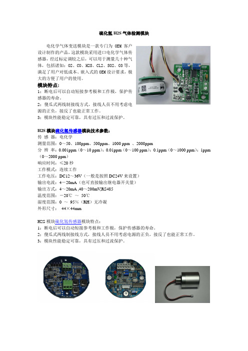
硫化氢H2S气体检测模块
电化学气体变送模块是一款专门为OEM客户
设计制作的产品,这款模块采用进口电化学气体传
感器,经过标定调较之后,可以用于测量几十种气
体,包括诸如:O2、CO、H2S、CL2、SO2、O3等,
满足了用户对低成本、嵌入式的OEM设计要求,极
大的方便了用户的使用。
模块特点:
1:断电后可以自动短接参考极和工作极,保护传
感器的寿命。
2:傻瓜式两线制接线方式,接线人员不用考虑电
源的正负,接反了也能正常工作。
3:模块性能稳定可靠,具有过压和过流保护。
H2S模块硫化氢传感器模块技术参数:
传感器:电化学
测量范围:0~50、100ppm、500ppm、1000 ppm 、2000ppm
分辨率:0.001ppm(0~10 ppm);0.01ppm(0~100 ppm);0.1ppm(0~1000 ppm);1ppm (0~2000 ppm)
响应时间:≤20秒
工作模式:连续工作
工作电压:DC12~36V(一般是按照DC24V来设置)
输出电流:4-20mA(也可直接输出继电器开关量)
输出方式:4~20mA ,40~200mV,RS485
温度范围:-20℃~50℃
湿度范围:0 ~95%(RH)无冷凝
外形尺寸:44×44mm
H2S模块硫化氢传感器模块特点:
1:断电后可以自动短接参考极和工作极,保护传感器的寿命。
2:傻瓜式两线制接线方式,接线人员不用考虑电源的正负,接反了也能正常工作。
3:模块性能稳定可靠,具有过压和过流保护。
硫化氢探头的原理

硫化氢探头的原理
硫化氢探头是一种用来检测硫化氢(H2S)气体浓度的传感器。
硫化氢是一种有毒、易燃气体,具有刺激性和窒息性,在工业生产和环境监测中具有重要的应用。
硫化氢探头的原理主要基于电化学和光学两种方法。
电化学方法是硫化氢探头常用的原理之一。
其原理是通过气体与电极表面的反应产生电流,并根据电流的大小来测量硫化氢气体的浓度。
硫化氢探头通常由两个电极组成,一个是工作电极,另一个是参比电极。
工作电极上覆盖有一种特殊的材料,例如金属氧化物或半导体材料,可以与硫化氢气体发生反应。
当硫化氢气体接触到工作电极上的材料时,会引起电极表面的氧化或还原反应,产生电流。
通过测量电流的大小,可以推断出硫化氢气体的浓度。
参比电极通常是一个稳定的电极,用来提供一个稳定的电势参考,以保证电极反应的可靠性和稳定性。
另一种常用的原理是光学方法。
硫化氢探头采用光学方法是因为硫化氢气体可以与某些化学物质发生反应,并产生特定的光谱信号。
一般来说,硫化氢探头中会有一个感光元件,例如光电二极管或光敏电阻。
当硫化氢气体接触到感光元件上的化学物质时,会引起化学物质的颜色变化或发生化学反应,从而改变感光元件对光的吸收能力。
通过测量感光元件对光信号的响应,可以推断出硫化氢气体的浓度。
总体来说,硫化氢探头的原理基于硫化氢气体与特定材料或化学物质的反应,利用电化学或光学方法测量反应产生的电流或光信号,从而确定硫化氢气体的浓度。
硫化氢探头在工业生产、环境监测等领域具有重要的应用,对于保障人体健康和环境安全具有重要的意义。
硫化氢传感器

硫化氢传感器:一项重要的环境保护技术近年来,环境保护已经成为了全球各国政府和民间团体的热点话题。
随着工业化和城市化的快速发展,大量的有害气体和化学物质排放给环境带来巨大的威胁。
其中,硫化氢被认为是一种高度有害的气体,对人类身体健康和自然生态环境都带来了不可避免的危害。
为了有效地控制和减轻硫化氢对环境的影响,的研发和应用显得尤为重要。
一、的基本原理是用于检测并 quant 转硫化氢浓度的一种设备。
通常工作于一定的温度、湿度和大气压等条件下。
它们的基本结构通常由传感元件、放大器、显示器和控制电路等部分组成。
传感元件一般采用半导体、电化学或红外光学等不同的技术,它们具备不同的检测速度、灵敏度和电子学特性。
其中,半导体是一种最常见的传感器,它是用玻璃或石英管封装一个半导体材料,通过半导体材料与空气接触并发生化学反应,从而测量硫化氢浓度。
电化学则是采用电化学原理测量硫化氢气体的浓度,它们的精度和灵敏度一般比半导体高。
红外线则是利用硫化氢特殊的吸收光谱进行测量,测量精度比较高且对其他气体的干扰较小。
目前研发中的微机电系统(MEMS)具有更高的灵敏度和稳定性。
二、的应用范围硫化氢被广泛应用于生物制造、化学工业、碳化物制造、纺织加工、食品加工、医疗废物处理等领域。
在饲养场等生产领域中,硫化氢是由动物粪便、糞尿、沼气等发酵物质释放出来的。
在化工和制药工业中,硫化氢是生产过程中常见的废气之一。
硫化氢气体浓度高、味道难闻、易燃易爆,如果时间长、浓度过高的话,会对人体、环境产生非常严重的危害。
应用得相当广泛,主要目的是用于环保、安全、减少人力、物力资源浪费等。
以生产领域为例,可以用于检测饲养场的沼气,从而有效地控制有害气体的排放,保护当地生态环境。
在化工和制药工业中,可用于检测和控制生产过程中的硫化氢排放,避免对员工身体健康和环境的影响。
此外,在卫生保洁、医疗等方面,也有着广泛的应用。
三、的发展前景在全球环保政策的倡导下,已经被广泛应用于各个领域。
硫化氢检测传感器资料
目录H2S气体传感器 (2)1、H2S电化学传感器(Transducer 或sensor) (2)2、H2S固体传感器 (3)3、高灵敏光波导传感器检测H2S气体2007、2012年 (4)3.1 玻璃光波导的制备 (4)3.2 检测H2S 的原理 (5)4、基于红外激光光谱的开放式H2S气体传感器 (6)4.1基本原理 (6)4.2实验装置 (7)4.3实验与讨论 (8)5、基于激光吸收光谱天然气脱硫中H2S检测系统研究 (9)5.1 测量原理 (9)5.2 系统设计 (10)5.3 硫化氢吸收波长选择 (10)5.4 Herriot多次反射吸收池 (11)6、检测天然气中H2S气体浓度的光子带隙光纤传感器 (11)6.1 气体的吸收原理 (11)6.2 检测系统结构 (11)7、差分吸收式光纤甲烷气体传感器的研究(也有检测硫化氢的,原理方法相同) 127.1 差分吸收光纤传感机理 (12)7.2 差分吸收光纤传感器及其系统 (14)7.3 试验及其结果 (15)H2S气体传感器畜牧业中会接触到包括H2S,CH4,NH3等有毒有害气体,对动物及工作人员构成健康威胁。
在工业中伴随重大灾难性事故的发生而排放的有毒有害废气,也会对人们的生命健康造成损害。
H2S 是一种无色、易燃、有臭鸡蛋味的气体,作为一种剧毒性物质,对人体具有一定的危害性,因此监测H2S的浓度对人体健康有着重要意义。
H2S传感器的设计涉及多方面技术,大部分H2S检测方法主要应用电分析技术。
传统的H2S 气体检测方法主要有碘量法、分光光度法、汞量滴定法和电化学法等,但是存在灵敏度不高、费时费力,不适合现场实时快速检测。
而传感器具有携带方便、响应快、灵敏度高、易微型化、能用于现场分析和监控等特点。
气体传感器主要有半导体类传感器、质量类传感器、电化学类传感器和光学类传感器。
其中光波导(Optical Waveguide ,OWG)传感器具有常规气体传感器无法比拟的灵敏度高、体积小、抗电磁干扰、便于集成等优点,在传感器领域中占有越来越重要的地位。
特种气体固态电化学传感器 H2S 传感器 单元数据手册说明书
特种气体H2S传感器单元数据手册版本号:Ver1.01声明本说明书的版权归上海微雀传感科技有限公司所有。
非常感谢您使用上海微雀传感科技有限公司的H2S传感器单元,在使用前请仔细阅读本说明书,并按照本说明书介绍的方法使用H2S传感器单元,如果不按照本说明书介绍的方法使用,由此造成的损伤和破坏,本公司将不承担任何责任和由此带来的任何损失。
本说明书的解释权归上海微雀传感科技有限公司所有。
一,产品描述H2S传感器单元是上海微雀传感科技有限公司研发的针对H2S气体传感器电路,可以有效的将传感器信号转换成数字信号,并以UART方式进行传输。
H2S传感器单元已经完成出厂标定,同时具有灵敏度高、噪声低、尺寸小、稳定性高等优点。
一致性好、重复精度高,便于工程师设计相关产品。
二,应用领域★工业安全★生命安全★空气净化控制★空气质量监测★智能家居三,产品优点★抗高度过载★已经完成量程内气体标定★数字输出★高灵敏度★小尺寸★功耗低★暖机时间短★响应速度快★寿命长H2S传感单元外观四,传感器参数常规测量范围:100ppm(可定制)最低检出限:2ppm分辨率:<0.1ppm综合精度:+2%FS注:参考仪表检测国家标准GB12358-2006T50时间:<30S(测试条件温度:25摄氏度,湿度:50%,流速500ml/min)T90时间:<60S(测试条件温度:25摄氏度,湿度:50%,流速500ml/min)过载量程:300PPM工作温度范围:-20°C---50°C工作湿度范围:20%---95%R.H(非凝露)气压范围:800–1200hPa建议储藏温度:0-20°C,30-50%R.H建议储藏时间:<12个月寿命:工业类应用5年以上,商用类应用10年型号:AW-H2S-200五,传感器单元尺寸传感器单元上半部分传感器单元下半部分传感器单元隔爆片固定圈六,传感器单元电气参数工作电压:4.5V~5.5V最大电流:5mA工作温度:-20°C~50°C工作湿度:5~95%RH(非冷凝)工作气压:80~120KPa七,接口定义接口为5PIN,-TB200为2.0MM间距的接插件,-TB200A为1.25MM间距的接插件红色线VCC电源(4.5V~5.5V)蓝色线RXD模组接收端,外部发射端绿色线TXD模组发射端,外部接收端NC NC不焊接黑色线GND地UART接口的协议为波特率:9600数据位:8位效验位:无停止位:1位。
硫化氢H2S传感器放大电路板

硫化氢H2S气体检测模块SKA/H2S-101NE Sensor硫化氢H2S气体检测模块产品概述SKA/H2S-101硫化氢气体检测模块是一款专门针对空气中存在的硫化氢H2S气体,进行24小时实时在线监测浓度含量的模块产品。
是圣凯安科技采用原装进口最优质的气体传感器,通过32位微处理器和24位数据采集器后,再多次进行全量程的温湿度补偿。
然后再用99.999%纯度的标准气体进行标定校准之后的产品模块。
可直接输出模拟电流4-20mA,模拟电压0.4-2V、0-5V,数字信号TTL,R S485通讯协议等信号。
因此,您购买后,无需二次开发,即可直接选用标准信号,进行数据传输、在线监测等工作。
SKA系列有毒有害、PID气体检测模块全部采用原装进口最优质的气体传感器,具体响应速度快、无零点漂移、一致性好等特点。
选用品牌包括英国CITY、德国SOLID、英国ALPHASENSE、瑞士MEMBRAPOR、英国DYNANENT、日本NEMOTO、美国BASELINE等产品优势●本案电路设计已经防止电路反接、电压过高、电流过大,同时产品设计考虑防雷。
●大屏幕液晶显示可24小时在线监测,实时显示气体浓度变化值。
●国外原装进口气体传感器,反应速度快、无零点漂移、低误差率、一致性好、抗干扰能力强。
●智能型软件处理:32位微处理器+24位采集芯片,可在00.000-99999数值之间任意值测量检测。
●多种量程单位可选:%LEL、%VOL、PPM、PPB、ug/m3;●多次实验检测全量程温湿度补偿和数据校准,大大提高了产品的精确度和稳定性。
●可检测500多种有毒有害气体,国内最全。
●信号输出:模拟电流4-20mA,模拟电压0.4-2V、0-5V,数字信号TTL,R S485通讯协议等信号;并可以选配1-2组继电器(开关量信号)信号输出,方便与风机或电磁阀的控制设备联动使用。
技术参数产品名称硫化氢H2S气体检测模块SKA/H2S-101检测气体硫化氢H2S检测原理电化学原理检测范围0-50ppm、0-100ppm、0-200ppm、0-500ppm、0-1000ppm、0-2000ppm、0-5000ppm等量程可选。
电化学硫化氢传感器的原理

电化学硫化氢传感器的原理电化学硫化氢传感器的原理
电化学硫化氢气体传感器依据电化学的原理作业,运用待测气体在电解池中作业电极上的电化学氧化进程,经过电子线路将电解池的作业电极和参比电极安稳在一个恰当的电位,在该电位下能够发作待测气体的电化学氧化,因为氧在氧化和复原反响时所发作的法拉第电流很小,能够疏忽不计,所以待测气体电化学反响所发作的电流与其浓度成正比并遵照法拉第规矩。
这么,经过测定电流的巨细就能够断定待测气体的浓度。
电化学硫化氢传感器的功用
化学传感器首要由两有些构成:辨认体系;传导或改换体系。
辨认体系反待测物的某一化学参数(常常是浓度)与传导体系连结起来。
它首要具有两种功用:挑选性地与待测物发作效果,反所测得的化学参数转化成传导体系能够发作照应的信号。
分子辨认体系是决议悉数化学传感器的要害要素。
因而,化学传感器研讨的首要疑问即是分子辨认体系的挑选以及怎样反分子辨认体系与适宜的传导体系相接连。
化学传感器的传导体系承受辨认体系照应信号,
并经过电极、光纤或质量活络元件将照应信号以电压、电流或光强度等的改动方法,传送到电子体系进行拓展或进行改换输出,终究使辨认体系的照应信号改动为咱们所能用作剖析的信号,查看出样品中待测物的量。
电化学传感器工作指南及电路图

电化学传感器工作指南及电路图本公司有毒气体检测传感器的开发始于1981年,以一氧化碳传感器的研制为开端。
之后对各式各样新传感器都进行了开发。
直至最进开发的臭氧和氧化乙烯传感器,形成了系列的传感器产品,并以其可靠、稳定和耐用等特点斐声海内外。
此类传感器系一微型燃料电池,设计成为免维护型并且能长时间稳定工作的产品。
所采用的技术立足于己于人本公司早期氧传感器的工作基础,系直接响应气体的体积浓度变化,而不是响应其压力的变化。
该类传感器设计的最大特点是采用了气体的扩散势垒,该势垒能限制气体流向敏感电极的流星。
敏感电极能与到达电极的电化学活性仍有余裕。
这一高的电化学活性保证了传感器的长寿命和很好的温度稳定性。
两电极系统基于电化学原理工作的传感器其最简单的一种型式就是两电极系统。
其工作电极和对电极由一薄层电解液隔开并经由一个很小的电阻联通外电路。
当气体扩散进入传感器后,在敏感电极表面进行氧化或还原反应,产生电流并通过外电路流经两个电极。
该电流的大小比例于气体的浓度,可通过外电路的负荷电阻予以测量。
为了让反应能够发生,敏感电极的电位必须保持在一个特定的范围内。
但气体的浓度增加时,反应电流也增加,于是导致对电极电位改变(极化)。
由于两电极是通过一个简单的负荷电阻连接起来的,虽然敏感电极的电位也会随着对电极的电位一起变化。
如果气体的浓度不断地升高,敏感电极的电位最终有可能移出其允许范围。
至此传感器将不成线性,因此两电极气体传感器检测的上限浓度受到一定限制。
三电极系统对电极的极化所受的限制可以用引进第三电极,参考电极,和利用一外部的恒电位工作电路来予以避免。
在这样一种装置中,敏感电极曲线相对于参考电极保持一固定值。
在参考电极中无电流流过,因此这两个电极均维持在一恒定的电位。
对电极则仍然可以进行极化,但对传感器而言已不产生任何限制作用。
因此三电极传感器所能检测浓度范围要比两电极大得多。
大部分有毒气体传感器(3/4/7系列)均属三电极系统。
- 1、下载文档前请自行甄别文档内容的完整性,平台不提供额外的编辑、内容补充、找答案等附加服务。
- 2、"仅部分预览"的文档,不可在线预览部分如存在完整性等问题,可反馈申请退款(可完整预览的文档不适用该条件!)。
- 3、如文档侵犯您的权益,请联系客服反馈,我们会尽快为您处理(人工客服工作时间:9:00-18:30)。
AAN 105-03DESIGNING A POTENTIOSTATIC CIRCUITIntroductionIn a three-electrode sensor, each electrode has a specific use:• The working electrode responds to the target gas, either oxidising or reducing the gas, creating a current flow that is proportional to the gas concentration. This current must be supplied to the sensor through the counter electrode.• The reference electrode is used by the potentiostatic circuit to maintain a fixed potential at the working electrode. The working electrode potential must be maintained at the same potential as the reference electrode potential for unbiased sensors, or with an offset for sensors that require biasing.• The counter electrode completes the circuit with the working electrode, reducing some chemical species (normally oxygen) if the working electrode is oxidising, or oxidising if the working electrode is reducing the target gas. The potential of the counter electrode is allowed to float, sometimes changing as the gas concentration increases. The potential on the counter electrode is not important, so long as the potentiostat circuit can provide sufficient voltage and current to maintain the working electrode at the same potential as the reference electrode. Figure 1 is a circuit diagram of a zero bias potentiostat circuit. Refer to this during the discussions below.Figure 1 Preferred potentiostat circuit for zero bias toxic gas sensors. ICs require +/-, not single ended power supply.© Alphasense Limited Page 1 of 5 February 2003A typical potentiostat circuit consists of three parts:1 Control circuit with bias voltage, if required2 Current measuring circuit3Shorting FET to connect the working electrode to the reference electrode when power is off Control CircuitThe control op amp (IC2 in figure 1) provides the current to the counter electrode to balance the current required by the working electrode.The inverting input into IC2 is connected to the reference electrode and must not draw any significant current from the reference electrode. An op amp with an input bias current of less than 5nA is recommended.When switching on the circuit, the depletion mode JFET (Q1 in Fig 1)goes to a high impedance state and IC2 provides the current to maintain the working electrode at the same potential as the reference electrode. Any offset due to the input offset voltage in IC2 will therefore cause a sudden shift in potential at switch-on. Toxic gas sensors have a large capacitance, so significant currents can flow for small potential shifts, so ensure that your op amp has a low offset voltage, certainly less than 1 mV and preferably less than 100µV; also check the op amp offset voltage at the maximum usage temperature.Typically, for an oxidisable gas (such as CO) with a platinum reference electrode, the counter electrode will be -300 to -400mV from the ground potential. However, if hydrogen ions rather than oxygen molecules are reduced, then the potential could be as large as -1.05V. Also, reducing gases (such as NO2 or Chlorine) force the counter electrode to oxidise water, evolving oxygen; in this case the potential relative to the reference electrode is between +600 and +800 mV, depending on the type of reference electrode. Therefore, you must allow IC2 enough voltage swing to drive the counter electrode to the required potential and with sufficient current demanded by the sensor. If the circuit is unable to do this, then extreme non-linearities will occur at higher concentrations. It is best to allow ±1.1V swing on IC2 (plus any imposed bias voltage). This means that for a CO or H2S sensor the counter electrode wants to be typically -350 mV below the ground point, so IC2 needs a negative supply. If you are using a single ended low voltage power supply, pay particular attention to the available output swing on the op amp at the required current.Table 1 below shows the maximum generated steady state current for each type of sensor. At full scale no sensor generates more than 210µA, but allow at least 500µA for a general purpose circuit, although this can be decreased for specific, well tested sensor/ circuit combinations. Beware- when switching the circuit ON in the presence of an electroactive gas or when a new sensor is first connected, the sensor may give a surge current of several mA that may cause IC1 to clamp, depending on the current drive capacity of IC1; it is unlikely that IC1 can maintain the virtual earth on its inverting input with a high feedback resistor during such a high current transient. Always connect the sensor before powering the circuit.Circuit stability and noise reduction in the control circuit relies on R1, R2, C1 and C2; C2 may not be necessary for certain op amps. If eliminating C2, then C1 may be increased- between 10 and 100 nF. Suggested op amps are OP90 (single op amp) and OP 296 (dual op amp).© Alphasense Limited Page 2 of 5 February 2003Bias voltageNormally, Alphasense toxic gas sensors are operated in the zero bias mode; however, certain sensors, such as NO sensors, require a bias voltage: typically ±150 or 300mV for an NO sensor. Alternatively, sensor cross-sensitivity to certain gases can be enhanced by adding a bias voltage.BEWARE! performance can also be degraded if you bias incorrectly! Remember that biasing a normally unbiased sensor may damage the sensor and certainly voids the sensor warranty. Consult Alphasense for further advice.If you wish to inject a bias voltage then also ensure that your bias voltage is stable: changes of even a few mV can affect sensitivity to gases and rapid changes in the bias voltage by only a mV will generate transient effects for up to hours on the sensor output. A simple method of biasing the sensor is shown in figure 2 below. The 10K load resistor to ground can be removed to reduce the current on V bias.Biasing should be maintained when the instrument is switched off - this is normally accomplished by using a button cell battery that remains on at all times. In this case, the input offset of IC2 is not critical, but its drift with temperature etc. must be kept small.Current Measuring CircuitThe measuring circuit is a single stage op amp (IC1) in a transimpedance configuration; the sensor current is reflected across R4, generating an output voltage relative to the virtual earth. C3 reduces high frequency noise. It is sometimes desirable to use two opamp stages to give the required output; the first stage should use a low value for R4 to allow the circuit to oppose the sensor current in transient conditions, followed by a second voltage gain stage to give the required output. The input offset voltage of IC1 will add to the sensor bias voltage (as the working electrode will be offset from 0V) so the input offset should be kept low. Remember that the generated current can be either positive or negative: sensors that oxidise at the working electrode (e.g. CO) generate a © Alphasense Limited Page 3 of 5 February 2003current into IC2, while reducing working electrodes (e.g. Cl2 or NO2) sink a current. So for the second case, ensure that IC2 has adequate current sinking capability.The measuring circuit uses a combination of the (load resistor (R load) plus internal sensor resistance) and the (internal sensor capacitance) to establish an RC circuit; the selection of R load is a compromise between fastest response time (low resistance R load) and best noise (high resistance R load): this RC circuit affects both the rms noise and the response time: the response time increases linearly with increasing R load resistance, while noise decreases rapidly with increasing R load resistance. If you need highest resolution, then forfeit fast response time. Likewise, if fast response time is critical, then reduce the resolution of your display or sample the signal faster and average over several readings in software to eliminate jitter. Due to the low impedance nature of the circuit, it is better to use an opamp with low noise current (usually at the expense of noise voltage)to get the best overall noise performance.As sensor current flows through R load, there will be a small change to the sensor bias potential. This has the effect of increasing the sensor settling time as the sensor will require a short time to re-stabilise when gas is applied, but this transient will normally not be seen except at high gas concentrations and high R load resistance.Refer to Table 1 below to calculate the required gain for your measuring circuit. If your detector/ instrument does not use the full scale of the sensor, then simply multiply the Sensitivity by your Range to determine the maximum current from the sensor. Since the sensitivity is the typical value, allow 20% more than the typical full scale output into your A/D converter.Sensor FullScale(ppm)Sensitivity(nA/ppm)(typical)Full Scaleoutput(µA)Full Scaleoutput(V)Calibrationpoint(ppm)CO-BF, CO-B1, CO-BX1,000100100 1.00 400 CO-AF1,00070700.70400 CO-AX2,00065130 1.30400 CO-AE 10,00030300 3.00 2,000 CO-DF1,00040740.74400 H2S-AH 501,200600.60 20 H2S-BH502,000850.8520 H2S-A1 100750750.75 20 H2S-B1200370740.7420 H2S-BE2,00090180 1.80 400 H2S-AE2,000105210 2.10400 H2S-D1100140140.1420 SO2-AF20500100.10 20 SO2-BF100350350.3520 SO2-AE2,00070140 1.40400 NO2-A1 20-3508-0.08 10 NO2-B120-75022-0.2210 NO2-AE200-35070-0.75100 NO-A1,-B1250400100 1.0050 NO-AE1,000100100 1.00400 Cl2-A120-3708-0.0710 CL2-B120-900220.2210 Table 1. List of output parameters and calibration point for Alphasense toxic gas sensors.© Alphasense Limited Page 4 of 5 February 2003Shorting FETIt is normal practice to add a shorting FET for unbiased sensors so that the reference and working electrodes are shorted together (with a residual resistance of a few tens of ohms) when power is removed from the circuit. This ensures that the working electrode is maintained at the same potential as the reference electrode when the circuit is switched off. The shorting FET is normally open circuit as long as power is applied. This “zero bias” state ensures that when you switch the circuit back on, the sensor is ready immediately. If you do not use a shorting FET and leave the sensor open circuit when the circuit is off, the toxic gas sensor will take a few hours to stabilise when next switched on.If you are supplying a bias voltage through IC2, then when you switch off the circuit, the sensor will be zero biased and hence when you reapply a bias voltage it will take a significant time (up to several hours) for the sensor to re-establish equilibrium. It is recommended that, for biased circuits, the bias voltage be maintained on at all times and the shorting FET not used. This will not affect the operating life of the sensor.The JFET (Q1) should be a p-type FET. Recommended FET types include surface mount or TO-92 packages as per Table 2 below.Manufacturer Product Code TypeSiliconix SST177Surface MountSiliconix J175TO-92Siliconix J176TO-92Siliconix J177TO-92Fairchild J175TO-92Table 2. Recommended p-FETs for short circuiting reference and working electrodes when the potentiostat circuit is off.Noise, RFI/EMI ScreeningIdeally, the measuring and controlling op amps in a potentiostat are fitted directly underneath the sensor to keep the shortest leads because of the low impedance and low sensor currents. Alphasense Application Note AAN 103 gives further advice on reducing noise and improving RFI/EMI screening.Sensor CalibrationNote that toxic gas sensor sensitivities are variable,typically ±15%. So you must calibrate in software to correct for sensor-to-sensor sensitivity variations. Alphasense maintains a database of the sensitivity of every sensor tested at Alphasense, but remember that sensitivity will drift downwards with time, typically 0.5% to 2% per month, depending on the sensor type, relative humidity and gas concentration/ temperature conditions. See Application Note AAN 108 for more information.It is also normal to correct for temperature dependence of the sensitivity; zero current is not normally temperature corrected, but for measurements requiring high accuracy at low concentrations, contact Alphasense for advice.© Alphasense Limited Page 5 of 5 February 2003。