机械毕业设计英文外文翻译403驱动桥和差速器
毕业设计论文外文文献翻译机械设计制造及其自动化轴承的摩擦与润滑中英文对照
Friction , Lubrication of BearingIn many of the problem thus far , the student has been asked to disregard or neglect friction . A ctually , friction is present to some degree whenever two parts are in contact and move on each other. The term friction refers to the resistance of two or more parts to movement.Friction is harmful or valuable depending upon where it occurs. friction is necessary for fastening devices such as screws and rivets which depend upon friction to hold the fastener and the parts together. Belt drivers, brakes, and tires are additional applications where friction is necessary.The friction of moving parts in a machine is harmful because it reduces the mechanical advantage of the device. The heat produced by friction is lost energy because no work takes place. A lso , greater power is required to overcome the increased friction. Heat is destructive in that it causes expansion. Expansion may cause a bearing or sliding surface to fit tighter. If a great enough pressure builds up because made from low temperature materials may melt.There are three types of friction which must be overcome in moving parts: (1)starting, (2)sliding,and(3)rolling. Starting friction is the friction between two solids that tend to resist movement. When two parts are at a state of rest, the surface irregularities of both parts tend to interlock and form a wedging action. T o produce motion in these parts, the wedge-shaped peaks and valleys of the stationary surfaces must be made to slide out and over each other. The rougher the two surfaces, the greater is starting friction resulting from their movement .Since there is usually no fixed pattern between the peaks and valleys of two mating parts, the irregularities do not interlock once the parts are in motion but slide over each other. The friction of the two surfaces is known as sliding friction. A s shown in figure ,starting friction is always greater than sliding friction .Rolling friction occurs when roller devces are subjected to tremendous stress which cause the parts to change shape or deform. Under these conditions, the material in front of a roller tends to pile up and forces the object to roll slightly uphill. This changing of shape , known as deformation, causes a movement of molecules. As a result ,heat is produced from the added energy required to keep the parts turning and overcome friction.The friction caused by the wedging action of surface irregularities can be overcome partly by the precision machining of the surfaces. However, even these smooth surfaces may require the use of a substance between them to reduce the friction still more. This substance is usually a lubricant which provides a fine, thin oil film. The film keeps the surfaces apart and prevents the cohesive forces of the surfaces from coming in close contact and producing heat .Another way to reduce friction is to use different materials for the bearing surfaces and rotating parts. This explains why bronze bearings, soft alloy s, and copper and tin iolite bearings are used with both soft andhardened steel shaft. The iolite bearing is porous. Thus, when the bearing is dipped in oil, capillary action carries the oil through the spaces of the bearing. This type of bearing carries its own lubricant to the points where the pressures are the greatest.Moving parts are lubricated to reduce friction, wear, and heat. The most commonly used lubricants are oils, greases, and graphite compounds. Each lubricant serves a different purpose. The conditions under which two moving surfaces are to work determine the type of lubricant to be used and the system selected for distributing the lubricant.On slow moving parts with a minimum of pressure, an oil groove is usually sufficient to distribute the required quantity of lubricant to the surfaces moving on each other .A second common method of lubrication is the splash system in which parts moving in a reservoir of lubricant pick up sufficient oil which is then distributed to all moving parts during each cycle. This system is used in the crankcase of lawn-mower engines to lubricate the crankshaft, connecting rod ,and parts of the piston.A lubrication system commonly used in industrial plants is the pressure system. In this system, a pump on a machine carries the lubricant to all of the bearing surfaces at a constant rate and quantity.There are numerous other sy stems of lubrication and a considerable number of lubricants available for any given set of operating conditions. Modern industry pays greater attention to the use of the proper lubricants than at previous time because of the increased speeds, pressures, and operating demands placed on equipment and devices.Although one of the main purposes of lubrication is reduce friction, any substance-liquid , solid , or gaseous-capable of controlling friction and wear between sliding surfaces can be classed as a lubricant.V arieties of lubricationUnlubricated sliding. Metals that have been carefully treated to remove all foreign materials seize and weld to one another when slid together. In the absence of such a high degree of cleanliness, adsorbed gases, water vapor ,oxides, and contaminants reduce frictio9n and the tendency to seize but usually result in severe wear。
驱动桥汽车外文文献翻译、中英文翻译、外文翻译
驱动桥汽车外文文献翻译、中英文翻译、外文翻译The driving axle is an essential component of a ___。
It consists of several parts。
including a housing。
axle drive。
differential。
two axle shafts。
and final drives if necessary.The main purpose of the axle drive is to ___。
___.There are two types of axle drives: single and double-stage。
The single-stage type has a pair of gears。
while the double-stage type has two pairs of gears。
The drive ___ case。
To ce noise during n。
axle drive ___.In summary。
___。
It includes several components that work ___ to the wheels。
The axle drive shaft is an essential part of the axle drive。
and there are two types of axle drives。
To ce noise during n。
the driving gears are made with ___.When a car turns。
___ a greater distance than the inner ___。
thanks to the differential ns ___ around the slower side gear。
the inner ___。
机械制造及其自动化专业外文翻译--差速器壳体工艺及工装设计

外文原文Differential shell process and boring tooling design The motor car engine power transmission shaft and the clutch, and finally to drive around again assigned half shaft drive wheels, in this article, the drive power transmission way, it is the final assembly of the main parts is reducer and differential. Gear reducer is increased, the function of torque and completely on gear meshing gears, between are easy to understand. But more difficult to understand differential, what, why "differential differential"?The car is driven car differential main parts. It is in the power of both half shaft transmission shaft, allowing both half with different speed spinning wheels, satisfy both pure rolling form as possible, reducing equi-distant not tire and ground friction.Spider diagramObject graph theory differentialfunctionalAt the turn of the car wheel track line, if the car is circular arc, turn left at the center, and at the same time, the wheels went arc length, the wheels than to balance the difference, left, and right wheel wheels slowlySlip differentialFaster, with different speed up the distance.If you make a whole after wheel, can accomplish on both sides of the wheel speed difference, is also does not have an automatic adjustment. In order to solve this problem, a hundred years ago, France Renault automotive company founderluis Renault will design a differential this thing.Slip differentialconstituteOrdinary differential planetary wheel planetary gear, by plane (d ifferential shell), half axle gear parts etc. The power of the engine into the differential transmissionStructurePlanetary wheel frame, driven directly by the planets wheel driv e, right and left two half shaft, wheel drive left and right. Meet the design requirements of differential (left) and the shaft speed (right) = 2 (axial rotational speed) planet round frame. When the car goe s, left, right wheel and planetary wheel frame of equal speed, and in a state of equilibrium in the balance among car when turning ro und to destruction, reduce the speed, the wheel speed increase.StructurePrincipleThis adjustment is automatic differential here, involves "minimal energyconsumption principle", namely earth all objects are tend to minimum energy. Such a grain of beans in a bowl, beans will automatically stays in the bowl bottom and never stay in the bowl wall, because the bowl bottom is the lowest energy (potential), it automatically select static (minimum) without energy. In the same way,A 3d effectWheel in turning also will be the lowest power consumption tendency, automatically adjusted according to turn radius of the wheel speed around.When turning wheel, because the pull of the phenomenon, the medial wheel slip phenomenon, two driving wheel at will produce two opposite direction of additional force, due to the "principle of minimal energy consumption, will inevitably lead to the wheel speed different sides, thus destroyed the balance between three and half shaft are reflected by the half axle gear planetary gears, forced to produce the half shaft rotation speed, speed, the medial axis speed slow speed, so as to realize the difference on both sides wheels.If the drive wheels on both sides of the drive shaft with a whole rigid connection, only two wheels at the same Angle rotation. So, when the steering wheel, due to the lateral than inside the distance moved across the wheels, will make the scroll wheel on the slide, and drag on the scroll wheel inside the slip. Even the car run straight road gravamen, because although flat tire surface or rolling radius (but ranging from manufacturing error, wear different tyres, ranging from uneven pressure or carrying of sliding wheel) and cause.When the wheel sliding tire wear, not only aggravate increased power and fuel consumption, still can make steering difficulties, braking performance deterio rated. As for the wheels, and does not occur in structure sliding must ensure each wheel at different angles can rotate.Axis between differential driven wheels usually use bearing spindle support in the, can at any Angle rotation, and drive wheels with two and half shaft rigid connection, between two and half shaft with differential. The differential and called shaft between differential.Many of the drive shaft, and to make each off-road vehicle drive to different velocity rotating, in order to eliminate the bridge of the drive wheels, some in two axles sliding between between shaft with differential.Differential inspection1 differential shell doesn't have any properties of crack, shell and planetary gear differential half shaft washer, contact between gear, should be smooth without groove, If there is a slight groove or wear, can continue to use after grinding, or should be replaced or be repaired.2 the planetary gear differential shell and planetary gear wheel when the fitting clearance shall not greater than 0.1-0.15 mm, half axle gear shaft neck and shell hole for clearance, with no obvious loose labels should be replaced or feeling, or repair.Shell's processing technologyThe processing quality not only affects shell, the assembly precision and accuracy, but also affects the movement of the machine working accuracy, performance and life.There are many kinds of shell structure, its size and form with the structure of the machine and the shell in machine has the different function. But they rema in on the analysis from the craft had a lot in common and its structure features are:(1) appearance is basically composed of six or five plane again into the closed-end polyhedron, integral and combined two,(2) structure shape is more complex. Inside the cavity is often, some places "partition wall, shell and uneven thickness thin.(3) shell walls are usually decorate have parallel hole or vertical hole,(4) on the shell, main processing is the number of plane, in addition to many higher accuracy and precision of supporting bearing with less demanding tighten pore.Shell parts technical requirements:(1) bearing support size precision and accuracy, surface roughness, requirements,(2) position precision including hole axis of the distance between the dimension precision, the same axis parallel degree in each hole, and KongDuan facing the coaxial tolerance of vertical axis holes; etc.(3) to meet the needs and positioning of the shell processing machine assembly request, shell and assembly of shell with the datum plane positioning due and certain degree, and the surface roughness requirements, The bearing hole and assembling a certain distance between datum due to the accuracy requirement of the size.中文译文差速器壳体工艺及工装设计汽车发动机的动力经离合器、变速器、传动轴,最后传送到驱动桥再左右分配给半轴驱动车轮,在这条动力传送途径上,驱动桥是最后一个总成,它的主要部件是减速器和差速器。
中英文文献翻译-减速器和差速器的调整与装配
附录 A 外文文献Farm Machinery Using & MaintenanceThe most important thing is the meshing mark and meshing backlash of the driven bevel gears and active bevel gears, the firmness adjustment of half axle gears and planetary gear in maintenance of the BJ2020S jeep driving axle . This is an important and difficult job ,because the rear axle and driven working under the large load and high speed. And the bear is alternating load. If the meshing mark is not conforming to requirements or the meshing backlash is not good, it will appear smooth transmission speed and noise, wear, or even broken tooth gear, which directly influences the car service life and various tasks when it is working. At the same time , lord and driven tapered gear meshing mark and the check assembly and adjustment became a complicated problem although automobile driving axle structure is not a very complicated but some people is not familiar with the principle on gear transmission. Based on years of teaching and practice in the maintenance work with the adjustment of BJ2020S jeep driving axle differential gears and bearings has some method and steps of the relevant views and comments about something.ⅠAdjustment of the axis gear differential planetary gear mesh clearanceHalf axle gears and planetary gear mesh clearance is adjusted by half axle gears and differential shell thickness between three different (0.5 mm, 1.0 mm, 0.2 mm) thrust washers . Because of the planetary gear differential between shell with the thrust washers, so it must be the half axle gears through the thrust washers (two half axle gears and add, subtract washers), and the gap of the planetary gear mesh. Then using pins will planetary gear axle fixed.ⅡAdjustment of differential backlashThis bearing clearance is adjusted by adding, subtracting differential bearings and differential between shell thickness (0.5 mm in four different, o. mm, 0.15 ram, 0.10 ram) to adjust the adjustment of the gasket. In the adjustment of the former ready right and left bridge between shell of gasket, installation fixed good follower bevel gears. Active bevel gears should not installed in accordance with the relevant provisions of the torque (40-60N, m) installed left and right with tapered bridge housing, active gear with long bar, or a screwdriver to turn down, or pry differential assembly, to check differential assemblybearings between differential to feel no axial clearance and rotate freely.ⅢActive bevel gears bearing clearance adjustmentIn active position of bevel gears can be determined by the basic, increase and decrease active bevel gears with active before bearings taper gear bearing thrust ring between four different thickness (0.10 mm, 0.15 ram, 0.25 mm mm) adjustment, 0.50 gasket to adjust, the flexible rotation, no axial and radial clearance.ⅣActive bevel gears and driven bevel gears clearance and meshing mark adjustment Domestic automobile gear for no modifier, assembling widely adopted, the first meshing mark check whether the meshing mark requirements, such as requirements, through the change of bevel gears, driven axial position to get to meet the requirements of meshing mark, the active bevel gears bearing and differential bearing clearance (pre-tightening degrees) basis, rub-up, driven bevel gears, initiative on 3-4 taper gear teeth are coated with thin layer opposite, oil (or face turns into oil), according to the requirements and differential assembly installed left, right, forward and backward bridge housing, then turn active bevel gears decomposition of left and right to bridge housing, driven gear tooth surface of conical whether imprint requirements. If meshing mark requirements, visible to the situation by outward, to the right or left, bevel gears, driven to adjust. When the meshing mark to tooth root cap, the main, small or client, the formula for the Lord: "the Lord, from (i.e., big into bevel gears into active driven gear), small (i.e. driven out from bevel gears removed from active gear)." When the Lord, driven gear cone of meshing mark complies with the standards and inspection, driven bevel gears, active bevel gears and clearance of bevel gears driven backlash should actively bevel gears in the radius of 45mm flanges on the circumference displacement measurement, the arc length) should be in (0.2-0.6 mm. If does not accord with a standard, can increase and decrease active bevel gears and bearings taper gear after the shim between left and right or mobile differential bearing adjustment gasket, driven to adjust the gap, so bevel gears, driven when the bevel gears has adjusted, adjust the marks are not destroyed, small volume, driven tapered gear meshing mark.ⅤDrive and differential assemblyWe can start assemble the drive and differential when the differential gears, driven gear, each bearing, tapered meshing mark adjustment is over. Based on the thickness of the gasket and the bolt torques, we should coated with rubber seal, assembled active bevelgears, mount differential assembly, then closed the bridge housing.附录 B 中文译文减速器和差速器的调整与装配在对BJ2020S吉普车后桥的维修中,最主要的就是减速器主、从动圆锥齿轮的啮合印痕及啮合间隙;差速器半轴齿轮、行星齿轮啮合间隙和各轴承松紧度的调整。
机械毕业设计英文外文翻译402驱动桥和差速器 (2)

附录附录ADrive axle/differentialAll vehicles have some type of drive axle/differential assembly incorporated into the driveline. Whether it is front, rear or four wheel drive, differentials are necessary for the smooth application of engine power to the road.PowerflowThe drive axle must transmit power through a 90° angle. The flow of power in conventional front engine/rear wheel drive vehicles moves from the engine to the drive axle in approximately a straight line. However, at the drive axle, the power must be turned at right angles (from the line of the driveshaft) and directed to the drive wheels.This is accomplished by a pinion drive gear, which turns a circular ring gear. The ring gear is attached to a differential housing, containing a set of smaller gears that are splined to the inner end of each axle shaft. As the housing is rotated, the internal differential gears turn the axle shafts, which are also attached to the drive wheels.Fig 1 Drive axleRear-wheel driveRear-wheel-drive vehicles are mostly trucks, very large sedans and many sports car and coupe models. The typical rear wheel drive vehicle uses a front mounted engine and transmission assemblies with a driveshaft coupling the transmission to the rear drive axle. Drive in through the layout of the bridge, the bridge drive shaft arranged vertically in the same vertical plane, and not the drive axle shaft, respectively, in their own sub-actuator with a direct connection, but the actuator is located at the front or the back of the adjacent shaftof the two bridges is arranged in series. Vehicle before and after the two ends of the driving force of the drive axle, is the sub-actuator and the transmission through the middle of the bridge. The advantage is not onlya reduction of the number of drive shaft, and raise the driving axle of the common parts of each other, and to simplify the structure, reduces the volume and quality.Fig 2 Rear-wheel-drive axleSome vehicles do not follow this typical example. Such as the older Porsche or Volkswagen vehicles which were rear engine, rear drive. These vehicles use a rear mounted transaxle with halfshafts connected to the drive wheels. Also, some vehicles were produced with a front engine, rear transaxle setup with a driveshaft connecting the engine to the transaxle, and halfshafts linking the transaxle to the drive wheels.Differential operationIn order to remove the wheel around in the kinematics due to the lack of co-ordination about the wheel diameter arising from a different or the same rolling radius of wheel travel required, inter-wheel motor vehicles are equipped with about differential, the latter to ensure that the car driver Bridge on both sides of the wheel when in range with a trip to the characteristics of rotating at different speeds to meet the requirements of the vehicle kinematics.Fig 3 Principle of differentialThe accompanying illustration has been provided to help understand how this occurs.1.The drive pinion, which is turned by the driveshaft, turns the ring gear.2.The ring gear, which is attached to the differential case, turns the case.3.The pinion shaft, located in a bore in the differential case, is at right angles to the axle shafts and turns with the case.4.The differential pinion (drive) gears are mounted on the pinion shaft and rotate with the shaft .5.Differential side gears (driven gears) are meshed with the pinion gears and turn with the differential housing and ring gear as a unit.6.The side gears are splined to the inner ends of the axle shafts and rotate the shafts as the housing turns.7.When both wheels have equal traction, the pinion gears do not rotate on the pinion shaft, since the input force of the pinion gears is divided equally between the two side gears.8.When it is necessary to turn a corner, the differential gearing becomes effective and allows the axle shafts to rotate at different speeds .Open-wheel differential on each general use the same amount of torque. To determine the size of the wheel torque to bear two factors:equipment and friction. In dry conditions, when a lot of friction, the wheel bearing torque by engine size and gear restrictions are hours in the friction (such as driving on ice), is restricted to a maximum torque, so that vehicles will not spin round. So even if the car can produce more torque, but also need to have sufficient traction to transfer torque to the ground. If you increase the throttle after the wheels slip, it will only make the wheels spin faster.Fig 4 Conventional differential Limited-slip and locking differential operationFig 5 Limited-slip differentialDifferential settlement of a car in the uneven road surface and steeringwheel-driven speed at about the different requirements; but is followed by the existence of differential in the side car wheel skid can not be effective when the power transmission, that is, the wheel slip can not produce the driving force, rather than spin the wheel and does not have enough torque. Good non-slip differential settlement of the car wheels skid on the side of the power transmission when the issue, that is, locking differential, so that no longer serve a useful differential right and left sides of the wheel can be the same torque.Limited-slip and locking differential operation can be divided into two major categories:(1) mandatory locking type in ordinary differential locking enforcement agencies to increase, when the side of the wheel skid occurs, the driver can be electric, pneumatic or mechanical means to manipulate the locking body meshing sets of DIP Shell will be with the axle differential lock into one, thus the temporary loss of differential role. Relatively simple structure in this way, but it must be operated by the driver, and good roads to stop locking and restore the role of differential.(2) self-locking differential installed in the oil viscosity or friction clutch coupling, when the side of the wheel skid occurs when both sides of the axle speed difference there, coupling or clutch friction resistance on the automatic, to make certain the other side of the wheel drive torque and the car continued to travel. When there is no speed difference on both sides of the wheel, the frictional resistance disappeared, the role of automatic restoration of differentials. More complicated structure in this way, but do not require drivers to operate. Has been increasingly applied in the car. About non-slip differential, notonly used for the differential between the wheels, but also for all-wheel drive vehicle inter-axle differential/.Gear ratioThe drive axle of a vehicle is said to have a certain axle ratio. This number (usually a whole number and a decimal fraction) is actually a comparison of the number of gear teeth on the ring gear and the pinion gear. For example, a 4.11 rear means that theoretically, there are 4.11 teeth on the ring gear for each tooth on the pinion gear or, put another way, the driveshaft must turn 4.11 times to turn the wheels once. The role of the final drive is to reduce the speed from the drive shaft, thereby increasing the torque. Lord of the reduction ratio reducer, a driving force for car performance and fuel economy have a greater impact. In general, the more reduction ratio the greater the acceleration and climbing ability, and relatively poor fuel economy. However, if it is too large, it can not play the full power of the engine to achieve the proper speed. The main reduction ratio is more Smaller ,the speed is higher, fuel economy is better, but the acceleration and climbing ability will be poor.附录B驱动桥和差速器所有的汽车都装有不同类型的驱动桥和差速器来驱动汽车行驶。
吉林大学机械学院本科毕业设计外文翻译格式

本科生毕业设计(论文)翻译资料中文题目:配合新一代液力变矩器的柴油动力线的一些特性英文题目:some properties of a diesel driveline with hydrodynamic torque converters of thelastest generation学生姓名:学号:班级:专业:机械工程及自动化指导教师:吉林大学机械科学与工程学院Some properties of a diesel drive line withhydrodynamic torque converters of the latestgenerationAbstractDynamic properties of a drive line with a controlled Diesel engine, hydrodynamic transmission mechanism, additional gearing and a loading-working machine producing common monoharmonic loading are investigated. Solution of the dynamic problem is based on phenomenological experimental data: drivingtorque-speed characteristic in the part of the prime mover and so-called external static characteristic in the hydrotransmission part. The non-linear task is solved by a modified harmonic balance method that was described in preceding publications by the author.Keywords: Machine drive line; Controlled Diesel drive; Hydrodynamic torque converter; Working machine; Periodic loading; Stationary dynamic stateNomenclature and abbreviationsa, b --- ------Coulomb and viscous non-dimensional friction lossesA i,B i --- ----coefficients in mathematical expression of torque-speed characteristic i, i m ----------kinematic transmission, supplementary gearing transmission ratio -------mean reduced moment of inertia in driving and loading partI, I, k K ---------tangent slopes of λ(i) and K(i) curves respectivelykλK -------------moment transmissionM ------------Diesel-engine momentM D(ω, z) ----controlled torque-speed driving characteristicM Dmax(ω), M Dmin(ω) ---torque-speed characteristic for maximal and minimal fuel supplyM1, (), M2, () ---pump loading moment and turbine driving momentM T1, M T2 ----friction loss moment in driving and loading partM z, M za ----mean value and amplitude of loading moment-------------hydrodynamic converter characteristic radius吉林大学本科毕业论文外文翻译t -------------timeT, T D------------Watt regulator and Diesel-engine time constantu, z ---------gas lever and regulator displacementw -----------common dynamic variableε -----------regulator structural parameterζ -----------regulator damping ratioλ -----------coefficient of rotation momentν -----------loading angular velocity, π-------index denoting mean value and periodical component---------hydraulic medium density----------rotation angleω1, (), ω2 ---pump and turbine angular velocityDM ------Diesel-engineG, G D ---additional and Watt-regulator gearingHdPT ---hydrodynamic power transmissionIJ --------InjectorLM ------loading mechanism (working machine)P, R, T---pump, reactor, turbineArticle OutlineNomenclature1. Introduction2. Mathematical model of the system3. Stationary dynamic solution at monoharmonic loading4. Results evaluation and concluding remarks1. IntroductionDynamic properties of a drive line (actuating unit) consisting of a controlled Diesel engine (DM), hydrodynamic power transmission system (HdPT), additional gearing (G) and a loading mechanism (LM) or working machine are investigated. The working machine loads the prime mover and the transmissions with a prescribed moment. A simple idealised schematic layout of the complete system is given in Fig.1. The considered Diesel engine is a standard production: ZETOR 8002.1 controlled by a mechanical (Watt’s) or electronic regulator R D governing fuel injector IJ. In the place of the hydrodynamic power transmission there are gradually applied hydrodynamic torque converters of the latest generation that have been projected吉林大学机械科学与工程学院and tested in WUSAM (Research and Projecting Institute of Machines and Mechanisms), j.s.c. Zvolen, Slovakia. These converters represent a three component assembly composed of a rotational pump (P), turbine (T) and a reactor (R) that may revolve in one direction as a free wheel. Advantage of these converters is the fact that their external dimensions and the dimensions of their individual components are identical and they may be mutually changed and arbitrarily combined in order to reach demanded properties. They differ only by internal configuration and blade geometry. According to [1] up to now more than 70 various types have been experimentally tested and from them the ones have been chosen that optimally fulfilled required properties. The mechanical system under consideration represents a sophisticated energy transfer chain from a source––prime mover to working mechanism. Because every real drive is of finite power, any periodic loading always evokes vibrations of all the dynamic variables even though we suppose all the connecting shafts and gearings rigid and backlash free. The influence of dynamic loading on the prime mover may be just controlled by a suitable choice of the torque converter.Fig. 1. Schematic layout of the Diesel drive line.In the paper influence of constant and periodic loading on time course of all the dynamic variables of the system (and particularly on the variables of the prime mover) is investigated at application of some selected types of hydrodynamic torque converters of the latest generation. For fulfilling this task it is necessary to create a suitable mathematical model of the whole combined system and then find its stationary solution corresponding to a required loading.2. Mathematical model of the system吉林大学本科毕业论文外文翻译At the beginning it is necessary to emphasize that mathematical modelling of the drive line in question is based, in our approach, on knowledge of the published phenomenological data: stationary torque-speed characteristic of the prime mover and so-called external static characteristic of the applied hydrodynamic torque converter. It is a much simpler process than modelling based on thermodynamic equations of burning fuel mixture in the Diesel engine and on hydrodynamic equations of real streaming working medium in very complicated cavities of the torque converter. The characteristics are usually given by manufacturer of the individual system components. This is different and simpler approach to solution of the problem than one may find e.g. at Ishihara [2], Hrovat and Tobler [3], Kesy and Kesy [4], Laptev [5] and some others. The derived dimensional and non-dimensional mathematical models of the mechanical system are introduced in [6]. Thenon-dimensional, reduced, so-called single-shaft model (in the driving and loading part), was derived in the form of combined system of the following differential and algebraic equations:(1)(2)(3)(4)M2=KM1, (5)λ=λ(i), (6)K=K(i), (7)(8)吉林大学机械科学与工程学院(9) where the meaning of the individual symbols is explained in nomenclature. In the non-dimensional model all the dynamic variables and parameters are expressed by means of properly chosen relative standard quantities so that the model of the system might be the most simple. Transformation of the original equations system to the non-dimensional form Figs. (1), (2), (3), (4), (5), (6), (7), (8) and (9) is described in detail in [6]. As for this cited paper, it is necessary to say that the relative standard value of loading angular frequency has been settled according to the relation, where in denominator is relative standard value of time. For this value,the time constant of the regulator has been just chosen, i.e. , where therelated dimensional dynamic variables are distinguished by upper bars. The introduced mathematical model has nine variables: M, M1, ω1, z, λ, K, i, M2, ω2 and their meaning is explained in nomenclature. The first three equations represent mathematic model of the prime mover where in inertia moment I there is includedinertia moment of the pump and equivalent part of the working medium because driving and pump shafts are connected by a rigid clutch. The right side of Eq. (3) represents the controlled stationary torque-speed characteristic for which it holds: M D(ω1,z)=M Dmax(ω1)-[M Dmax(ω1)-M Dmin(ω1)]z, (10) where M Dmax(ω1), M Dmin(ω1) represent its non-dimensional extreme branches for maximal and minimal fuel supply and z is the non-dimensional regulator deviation.If the experimentally measured dependences M Dmax(ω1), M Dmin(ω1) are expressed by second degree polynomials then the controlled non-dimensional torque-speed characteristic has the form:(11) From the introduced model it is evident that at chosen parameter value u driving speed growth causes regulator displacement to increase and fuel supply to decrease. The idealised controlled torque-speed characteristic for a chosen parameter value u (gas lever displacement) is schematically depicted in Fig. 2. From Eq. (2) it is evident that the structural parameter ε must be chosen in such away that regulator self-oscillations should not occur. Eqs. Figs. (4), (5), (6), (7) and (8), in the sense of considerations in [6], represent the dynamic equations of the torque converter. Eq. (9) represents simplified motion equation of the loading mechanism under assumptiondoes not depend on rotation angle . In thisthat the reduced inertia moment Ireduced inertia moment there is involved inertia moment of the turbine with吉林大学本科毕业论文外文翻译equivalent part of the working medium too. It is obvious that in this inertia moment and in all moments of the loading mechanism there is considered gear ratio i m of the supplementary gearing of the originally non-reduced system. Eqs. Figs. (6) and (7) represent the external static characteristic of the hydrodynamic transmission, i.e. formal dependences of λ and K on the kinematic ratio i and the dependences are given for every converter type in graphical form. The dynamic variables λ and K are defined in non-dimensional form very simply by non-linear relations Figs. (4) and (5). In a general way these non-dimensional variables are defined by means of dimensional values (distinguished by upper bars) as follows:(12) where individual symbol meaning may be found in nomenclature. As we have chosen (according to Fig. 2) for the relative standard value of angular velocity the idle motion angular velocity of the Diesel engine at maximal fuel supply, i.e. at z = 0, then from Figs. (4) and (12) it is evident that the relative standard moment value is(13)It means that if for the applied drive s−1 and all the applied convertertypes have equal characteristic radius m and if we consider mean valuekg m−3 at stationary thermic regime then the relative standard value of themoment is N m for all the considered converter types. The external static characteristics of the applied converters with internal labelling: M350.222,M350.623M, M350.675, M350.72M3M, are (according to the measuring records [7]) successively introduced in Fig. 3(a)–(d). When the torque-speed characteristic is known and the measured dependences Figs. (6) and (7) are at disposal, it is possible to solve the combined system of differential and algebraic equations Figs. (1), (2), (3), (4), (5), (6), (7), (8) and (9). This is a little complicated task because the differential and algebraic equations in the accepted mathematical model arenon-linear. Stationary dynamic state of the system was calculated by a modified harmonic balance method that is fully described in [8].吉林大学机械科学与工程学院Fig. 2. Idealised diagram of the driving torque-speed characteristic.Fig. 3. External static characteristics of the hydrodynamic power transmissions: M350.222,M350.623M, M350.675, M350.72M3M.3. Stationary dynamic solution at monoharmonicloadingIn this section stationary solution of the system Figs. (1), (2), (3), (4), (5), (6), (7), (8) and (9) will be looked for always with the same prime mover and successively considering all the converters types whose external static characteristics are introduced in Fig. 3(a)–(d). If each of the nine dynamic variables is denoted by a common symbol w≡M, M1, ω1, z, λ, K, i, M2, ω2 then, in accordance with applied method, every dynamic variable may be formally expressed as a sum of its mean and its centred periodic component, i.e.:w=w+w π. (14) Following the mentioned method, on restrictive presumption that it holds:MM z→wπw, (15)吉林大学本科毕业论文外文翻译the system Figs. (1), (2), (3), (4), (5), (6), (7), (8) and (9) splits into twoindependent systems of equations: a system of non-linear algebraic equations for calculationw and a combined system of linearised differential and algebraic equations for calculation w π. If one considers that friction losses in the driving part are implicitly expressed already in the torque-speed characteristic of the drive and in the external static characteristic of the applied hydrodynamic torque converter and friction losses in the loading part are supposed as a combination of Coulomb and viscous friction, i.e.:M T 2=a +bω2, (16)then the non-linear algebraic system has the form:(17)The combined system of the linearised differential and algebraic equations is(18)where for writing abbreviation it is denoted:吉林大学机械科学与工程学院(19) The solution process of both equation systems Figs. (17) and (18) is introduced in [8]. The system of non-linear equations (17) was calculated for three parameter levels u (u = 0.3, 0.4, 0.6) that respond to 30%, 40%, and 60% of the maximal gas lever displacement. To each chosen parameter value u, a certain driving angular velocity interval responds. From Fig. 2 and from Eq. (2) it is evident that for a chosen value u the corresponding mean driving angular velocity value must lie in interval:ω1ω1b, (20)ωwhere for border values of the interval it holds:(21) For the chosen parameter value u = 0.3 and for different mean values M z, the calculated mean values w(for the drive line with given drive and all the consideredconverter types) are introduced in diagrams in Fig. 4(a)–(d). Analogical mean values w of the same variables corresponding with the parameter u = 0.4 are in Fig.5(a)–(d). Finally, the calculated mean values w corresponding with parameteru = 0.6 and identical torque converter types are depicted in Fig. 6(a)–(d). Here it is important to remind that x-coordinates in Fig. 4, Fig. 5 and Fig. 6 represent the mean angular velocity interval (20) gradually for parameters u = 0.3, 0.4, 0.6 and the decimal fractions on this section denote only its decimal division. From the calculated mean values w in Fig. 4, Fig. 5 and Fig. 6 and from the introducedexternal static characteristics in Fig. 3a complete nine of the mean values w can be determined for any mean loading value Mand estimated loss moment value M T2in the loading part. When this complete nine w is known then it is possible, in the sense of the applied method, to construct all the constant coefficients of the combined differential and algebraic system (18) for calculation wπ. This system is already linear and may be solved by known classical methods. First of all, we take interest in stationary dynamic solution. In sense of the procedure one may express the centred periodic component of every dynamic variable in the form:wπ=M za(W c cosνt+W s sinνt), (22) where notations W c, W s represent cosine and sine components of the dynamic factor (transmissibility) of corresponding dynamic variable. Detailed computing procedure is introduced in [8]. For transmissibility of the centred periodic component of every dynamic variable it holds:(23)As an example in Fig. 7, Fig. 8, Fig. 9, Fig. 10 and Fig. 11 there are successively introduced dynamic characteristics of the centred periodic components of dynamic variables: moment (M) and angular velocity of the drive (ω1), loading moment of the pump (M1), moment (M2) and angular velocity of the turbine (ω2) for the system with hydrodynamic converter M350.222 and for chosen parameter value u = 0.4. Results are given in two forms of dynamic characteristics, namely as classic frequency response functions (upper parts) and as Nyquist diagrams (lower parts). Both types of dynamic characteristics are calculated for four values of the loadingmechanism inertia moment: kg m2 and for supplementary gear ratio i m = 1. Equal sections of loading angular velocity Δν with value π corresponding to equal sections on frequency response function x-coordinates are in the Nyquist diagrams separated by bold points as well. In dynamic calculations, theDiesel-engine time constant s, regulator time constant s and the regulator damping ratio ζ = 0.55 were considered. The left parts of the dynamic characteristics in Fig. 7, Fig. 8, Fig. 9, Fig. 10 and Fig. 11 correspond to the dynamic regime with mean values: λ = 0.111, K = 3.12, i = 0.127, which are quantified bybold points on the left thin vertical in the external static characteristic in Fig. 3(a), when the converter works in so-called friction clutch regime. Mean values of dynamic variables, corresponding to this dynamic regime, are: M = 0.0506,= 0.158, ω1 = 0.673, ω2 = 0.0855, M z = 0.152, z = 0.0849. These values areMalso accentuated in Fig. 5(a) by bold points on thin vertical line. In this dynamic regime the converter works with mean transfer energy efficiency η≈ 0.405. Theright parts of the dynamic characteristics introduced in Fig. 7, Fig. 8, Fig. 9, Fig. 10 and Fig. 11 correspond to dynamic regime with mean values: λ = 0.111, K = 1.1,i = 0.74, represented by bold points on the right thin vertical on the external staticcharacteristic in Fig. 3(a) when the converter works in so-called moment converter regime with mean energy transfer efficiency higher than 0.8. The mean values of dynamic variables corresponding to this dynamic state are: M = 0.0506,M= 0.0557, ω1 = 0.673, ω2 = 0.4986, M z = 0.0466, z = 0.0849 and aremarked out in Fig. 5(a) as well on thin vertical line by bold points. Non-dimensional friction losses at dynamic calculation were considered according to (16) as follows:, , where is dimensional relative moment standard value (13).Fig. 4. Mean values of the chosen dynamic variables w of the system with converters: M350.222,M350.623M, M350.675, M350.72M3M for optional parameter u = 0.3.Fig. 5. Mean values of the chosen dynamic variables w of the system with converters: M350.222,M350.623M, M350.675, M350.72M3M for optional parameter u = 0.4.Fig. 6. Mean values of the chosen dynamic variables w of the system with converters: M350.222,M350.623M, M350.675, M350.72M3M for optional parameter u = 0.6.Fig. 7. Dynamic factor (transmissibility) of the centred periodic component of the system driving moment with the converter M350.222 in fretting clutch and moment converter regime for optionalparameter u = 0.4Fig. 8. Dynamic factor (transmissibility) of centred periodic component of the driving angular velocity of the system with the converter M350.222 in fretting clutch and moment converter regimefor optional parameter u = 0.4Fig. 9. Dynamic factor (transmissibility) of centred periodic component of the pump moment of the converter M350.222 in fretting clutch and moment converter regime for parameter u = 0.4.Fig. 10. Dynamic factor (transmissibility) of centred periodic component of the turbine moment of the converter M350.222 in fretting clutch and moment converter regime for parameter u = 0.4.Fig. 11. Dynamic factor (transmissibility) of centred periodic component of the turbine angular velocity of the system converter M350.222 at fretting clutch and moment converter regime forparameter u = 0.4.4. Results evaluation and concluding remarksIn the paper some dynamic properties of a Diesel drive line with some the latest generation torque converter types were inquired and stationary response to common monoharmonic loading was calculated. Mean values of all dynamic variables were calculated for the system with the same controlled drive and successively four chosen torque converter types. In order to save space, complete dynamic calculations are performed only for the system with converter M350.222 and results are introduced in form of frequency response functions and Nyquist diagrams.Already from the calculated mean values in Fig. 4, Fig. 5 and Fig. 6 one may judge technical possibilities and collaboration aptness of the applied drive with the considered converter type. Even from these diagrams it is evident that at application M350.222 this converter can work in arbitrary hydrodynamic regime when optional parameter value u 0.6. Working regime of the system adjusts automatically and depends only on external loading and parameter values u. At maximal loading and lower values u all the considered hydrodynamic converter work in hydrodynamic friction clutch regime when turbine rotation may even extremely decrease to zero value. At mean loading the converter works in the system as hydrodynamic moment converter with average energy transfer efficiency above 0.8. At low system loading and higher values u, the converter behaves as quasi-hydrodynamic fix clutch when relative working medium velocity is low and creates impression of stiffened substance. In this working regime angular velocities of all the converter rotating components are close to each other and mean energy transfer efficiency approaches theoretically to 1. From calculated mean values in Fig. 5 and Fig. 6 it is evident that the torque converters: M350.623M, M350.675, M350.72M3M can at optional parameter u 0.4 cooperate with given drive only in moment converter andhydrodynamic fix clutch regime respectively. The dynamical responses of the drive line with the torque converter M350.222 are depicted in Fig. 7, Fig. 8, Fig. 9, Fig. 10 and Fig. 11. In Fig. 7 and Fig. 8 dynamic factors (transmissibility) of moment and angular velocity of the drive are introduced. It is evident that at chosen value of damping ratio ζ = 0.55 only one significant resonance of these variables occurswhich lies always in loading frequency interval (), regardless of the fact in what regime the applied converter works. Resonance values of moment and angular velocity of the drive are significantly influenced by total inertia moment ofvalue is, the lower resonant values are. Verythe loading mechanism. The higher Isimply one can inquire influence of the supplementary gearing ratio i m because reduced inertia moment I z changes with its second power. It is interesting that change of the loading mechanism inertia moment does not shift resonant peak of dynamic characteristics that remain practically at the same loading angular frequency ν. Remarkable results may be observed in Fig. 9(a) and (b) where the dynamic factors of the pump loading moment corresponding to resonant values of moment and angular velocity of the drive are minimal and express small sensibility to I z magnitude in both inquired converter regimes. In Fig. 10 and Fig. 11, the dynamic factors of driving moment and angular velocity of the turbine are drawn for the case when the applied converter works in friction clutch and moment converter regime. Whole range of dynamic calculations has been made for different values of the time constant and regulator damping ratio ζ. It turned out that the drive linewith all the applied converter types has small sensibility to time constant magnitudeof the Watt regulator. Time constant changes in range (0.01–0.1 s) did not visibly reveal in calculated dynamic factors what is certain difference in comparison with hydrostatic transmission mechanisms (see e.g. [9]). On the other part, dynamic calculations prove that damping ratio ζ influences noticeably resonant values of all dynamic variables. The resonant transmissibility peaks of the driving moment M r and angular velocity ωr in dependence on damping ratio ζ, for the system with converter M350.222 and for four different loading inertia moment values areintroduced in Fig. 12(a) and (b). The thin dash lines always denote stationary resonant dynamic factor values of appertaining variable corresponding to zero-value loading frequency. Equally, as in previous cases, left parts of the Fig. 12(a) represent resonant values of moment and angular driving velocity when the applied converter works in hydrodynamic friction clutch regime. Analogically the right parts of the Fig. 12(b) represent resonant values of the same variable when the converter works in hydrodynamic moment converter regime. From the introduced diagrams it is evident that disturbance transmissibility from the loading mechanism to the drive grows with increasing damping ratio ζ. On the other part, dynamic calculations showed that for low damping ratio values (ζ 0.1) indication of a secondary resonance ofchosen variables appears in loading frequency band but the values of this secondary resonance are essentially lower than corresponding stationary values.Fig. 12. Transmissibility resonant values dependences of moment and driving angular velocity on damping ratio and on reduced inertia moment of the loading for the system with the at hydrodynamicclutch and moment converter regime at u = 0.4.配合新一代液力变矩器的柴油动力线的一些特性摘要:带有控制柴油机的车的动态特性,液力传导机制,还有传动装置和进行普通装卸工作的装载机的调查。
机械毕业设计英文外文翻译585主减速器和差速器
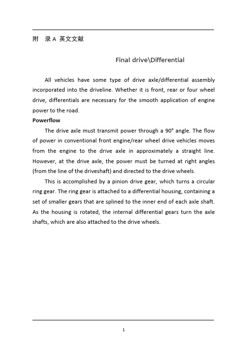
附录A 英文文献Final drive\DifferentialAll vehicles have some type of drive axle/differential assembly incorporated into the driveline. Whether it is front, rear or four wheel drive, differentials are necessary for the smooth application of engine power to the road.PowerflowThe drive axle must transmit power through a 90° angle. The flow of power in conventional front engine/rear wheel drive vehicles moves from the engine to the drive axle in approximately a straight line. However, at the drive axle, the power must be turned at right angles (from the line of the driveshaft) and directed to the drive wheels.This is accomplished by a pinion drive gear,which turns a circular ring gear. The ring gear is attached to a differential housing, containing a set of smaller gears that are splined to the inner end of each axle shaft. As the housing is rotated, the internal differential gears turn the axle shafts, which are also attached to the drive wheels.Fig 1 Drive axleRear-wheel driveRear-wheel-drive vehicles are mostly trucks, very large sedans and many sports car and coupe models. The typical rear wheel drive vehicle uses a front mounted engine and transmission assemblies with a driveshaft coupling the transmission to the rear drive axle. Drive in through the layout of the bridge, the bridge drive shaft arranged vertically in the same vertical plane, and not the drive axle shaft, respectively, in their own sub-actuator with a direct connection, but the actuator is located at the front or the back of the adjacent shaftof the two bridges is arranged in series. Vehicle before and after the two ends of the driving force of the drive axle, is the sub-actuator and the transmission through the middle of the bridge. The advantage is not onlya reduction of the number of drive shaft, and raise the driving axle of the common parts of each other, and to simplify the structure, reduces the volume and quality.Fig 2 Rear-wheel-drive axle Some vehicles do not follow this typical example. Such as the older Porsche or Volkswagen vehicles which were rear engine, rear drive. These vehicles use a rear mounted transaxle with halfshafts connected to the drive wheels. Also, some vehicles were produced with a front engine, rear transaxle setup with a driveshaft connecting the engine to the transaxle, and halfshafts linking the transaxle to the drive wheels.Differential operationIn order to remove the wheel around in the kinematics due to the lack of co-ordination about the wheel diameter arising from a differentor the same rolling radius of wheel travel required, inter-wheel motor vehicles are equipped with about differential, the latter to ensure that the car driver Bridge on both sides of the wheel when in range with a trip to the characteristics of rotating at different speeds to meet the requirements of the vehicle kinematics.Fig 3 Principle of differentialThe accompanying illustration has been provided to help understand how this occurs.1.The drive pinion, which is turned by the driveshaft, turns the ring gear.2.The ring gear, which is attached to the differential case, turns the case.3.The pinion shaft, located in a bore in the differential case, is at right angles to the axle shafts and turns with the case.4.The differential pinion (drive) gears are mounted on the pinion shaft and rotate with the shaft .5.Differential side gears (driven gears) are meshed with the pinion gears and turn with the differential housing and ring gear as a unit.6.The side gears are splined to the inner ends of the axle shafts and rotate the shafts as the housing turns.7.When both wheels have equal traction, the pinion gears do not rotate on the pinion shaft, since the input force of the pinion gears is divided equally between the two side gears.8.When it is necessary to turn a corner, the differential gearing becomes effective and allows the axle shafts to rotate at different speeds .Open-wheel differential on each general use the same amount of torque. To determine the size of the wheel torque to bear two factors: equipment and friction. In dry conditions, when a lot of friction, the wheel bearing torque by engine size and gear restrictions are hours in the friction (such as driving on ice), is restricted to a maximum torque, so that vehicles will not spin round. So even if the car can produce more torque, but also need to have sufficient traction to transfer torque to the ground. If you increase the throttle after the wheels slip, it will only make the wheels spin faster.Fig 4 Conventional differential Limited-slip and locking differential operationFig 5 Limited-slip differentialDifferential settlement of a car in the uneven road surface and steering wheel-driven speed at about the different requirements; but is followed by the existence of differential in the side car wheel skid can not be effective when the power transmission, that is, the wheel slip can not produce the driving force, rather than spin the wheel and does not have enough torque. Good non-slip differential settlement of the car wheels skid on the side of the power transmission when the issue, that is, locking differential, so that no longer serve a useful differential right andleft sides of the wheel can be the same torque.Limited-slip and locking differential operation can be divided into two major categories:(1) mandatory locking type in ordinary differential locking enforcement agencies to increase, when the side of the wheel skid occurs, the driver can be electric, pneumatic or mechanical means to manipulate the locking body meshing sets of DIP Shell will be with the axle differential lock into one, thus the temporary loss of differential role. Relatively simple structure in this way, but it must be operated by the driver, and good roads to stop locking and restore the role of differential.(2) self-locking differential installed in the oil viscosity or friction clutch coupling, when the side of the wheel skid occurs when both sides of the axle speed difference there, coupling or clutch friction resistance on the automatic, to make certain the other side of the wheel drive torque and the car continued to travel. When there is no speed difference on both sides of the wheel, the frictional resistance disappeared, the role of automatic restoration of differentials. More complicated structure in this way, but do not require drivers to operate. Has been increasingly applied in the car. About non-slip differential, not only used for the differential between the wheels, but also for all-wheel drive vehicle inter-axle differential/.Gear ratioThe drive axle of a vehicle is said to have a certain axle ratio. This number (usually a whole number and a decimal fraction) is actually a comparison of the number of gear teeth on the ring gear and the pinion gear. For example, a 4.11 rear means that theoretically, there are 4.11 teeth on the ring gear for each tooth on the pinion gear or, put anotherway, the driveshaft must turn 4.11 times to turn the wheels once. The role of the final drive is to reduce the speed from the drive shaft, thereby increasing the torque. Lord of the reduction ratio reducer, a driving force for car performance and fuel economy have a greater impact. In general, the more reduction ratio the greater the acceleration and climbing ability, and relatively poor fuel economy. However, if it is too large, it can not play the full power of the engine to achieve the proper speed. The main reduction ratio is more Smaller ,the speed is higher, fuel economy is better, but the acceleration and climbing ability will be poor.附录B 文献翻译主减速器和差速器所有的汽车都装有不同类型的主减速器和差速器来驱动汽车行驶。
差速器和车桥--中英文翻译
DIFFERENTIAL AND REAR AXLESThe differential is part of the rear-axle-housing assembly,which includes the differential,rear axles,wheels,and bearing.If the car were to be driven in a straight line without having to make turns,then no differential would be necessary.However,when the car rounds a turn,the outer wheel must travel farther than the inner wheel.The differential permits the two rear wheels to rotate different amounts when the car goes around a turn , while still delivering power to both rear wheels.The rear axles are attached to the wheels and have bevel side gears on their inner ends.The differential case is assembled on the left axle but can rotate on a bearing independently of the axle.The differential case supports the differential-pinion gear on a shaft,and this gear meshes with the two bevel gears.The fing gear is attached to the differential case so that the case rotates with the fing gear when the latter is driven by the drive pinion.The driving power enters the differential through the drive pinion on the end of the propeller shaft.The drive pinion is meshed with a large ring gear so that the ring gear revoves with the pinion.Attached to the ring gear is a differential-pinion shaft on which are assembled two differential-pinion gears.Each rear car wheel has a separate axle, and there are two side gears splined to the inner ends of the two wheel axles.The two side gears.When the car is on a straighet road ,the two differential-pinion gears do not rotate on the pinion shaft ,but they do exert pressure on the two side gears turn at the same speed as the ring gear ,causing both rear wheels to turn at the same speed,also.When the car rounds a curve ,the outer wheel must turn faster than the inner wheel,To permit this,the two pinino gears rotate on their pinion shaft,transmitting more turning movement to the outer side gear that to the inner side gear.Thus,the side gear on the outer-wheel axle turns more rapidly than the side gear on the inner wheel axle.This permits the outer wheel to turn more rapidly while the car is rounding the curve.There are two basic types of axle:deed axles and live axle.The dead axle does not rotate; the wheel rotates on it.A common exmple is the axle on a horse-drawn wagon.Live axles are attached to the wheel so that both the wheel and the axle rotate together.Live axles are classified according to the manner in which they are supported:semifloating, three-quarer-floating,and full-floating.AUTOMOBILE SYSTEMThe fuel system has the job of supplying a combustible mixture of air and fuel to the engine. The fuel system must vary the proportions of air and fuel to suit different operating conditions. When the engine is cold, for example, then the mixture must be rich(have a high proportion of fuel).The reason for this is that the fuel does not vaporize rapidly at low temperatures. Therefore, extra fuel must be added to the mixture so that there will be enough vaporized fuel to form a combustible mixture.The fuel system consists of the fuel tank, fuel pump, fuel filter, carburetor, intake manifold, and fuel lines, or tubes, connecting the tank, pump, and carburetor. Some gasoline engines use a fuel-injection system; in this system, a fuel-injection pump replaces the carburetor.The fuel tank, in which gasoline is stored, is normally located at the rear of the vehicle. It is made of sheet metal and is attached to the frame.A fuel pump delivers fuel from the tank to the carburetor. There are two general types of fuel pump, mechanical and electric.The fuel system has filters and prevent dire in the fuel from entering the fuel pump or carburetor. Dirt could, of course, prevent normal operation of these units and cause poor engine performance.The carburetor is essentially a mixing device which mixes liquid gasoline with air. In this process, it throws a fine spray of gasoline into air passing through the carburetor on its way to the engine. The gasoline vaporizes and mixes with the air to form a highly combustion chambers, where it is ignited. It burns, causing the engine to produce power. The mixture must be of varying degrees of rich nice to suit engine operating conditions.It must be rich(have a higher percentage of fuel)for starting, acceleration, and high-speed operation. And it should lean to(become less rich)for operation at intermediate speed with a worm engine. The carburetor has several different circuits, or passages, through which fuel and air-fuel mixture flow under different operating conditions to produce the varying richness of the air-fuel mixture.The purpose of the cooling system is to keep the engine at its most efficient operating temperature at all engine speeds and all drilling conditions.A great deal of heat is produced in the engine by the burning of the air-fuel mixture. Some of this heat escapes from the engine through the exhaust gases(the hot gases left after the gasoline is burned). But enough remains in the engine to cause serious trouble unless removed by some other means. The cooling system takes care of this additional heat.The cooling system is built into the engine. There are hollow spaces around each engine cylinder and combustion chamber. These hollow spaces are called waterjackets, since they are filled with water. When the engine is running, the water takes heat from the engine, becoming hot in the process.A water pump pumps the hot water from the engine water jackets into the radiator. The radiator has two sets of passages. One set carries air(pulled through by car motion and the engine fan). As the hot water passes through, it gives up its heat to the air passing through. The cooled water then reenters the engine, where it can pick up more heat. In operation, water continuously circulates between the engine and radiator, carrying heat from the engine temperatures are prevented.Two general types of cooling systems are used, air cooling and liquid cooling. The liquid cooling system consists of water pumps, water jackets, engine fan, radiator and so on. The water pump, driven by a belt from the engine crankshaft, circulates the cooling liquid between the radiator andengine water jackets. The cooling liquid is water. Antifreeze compounds are added to the water during the winter. The water jacket are cast into the cylinder blocks and heats. The engine fan is usually mounted on the water-pump shaft and is driven by the same belt that drives the pump shaft and the generator. The purpose of the fan is to provide a powerful draft of air through the radiator. The radiator is a device for holding a large volume of air so that heat will transfer from the water to the air. The radiator core is divided into two separate compartments; water passes through one, and air passes through the other.The ignition system is part of the electric system of the automobile. Its purpose is to produce high-voltage surges(up to 20 000 volts)and to deliver them to the combustion chambers in the engine. These high-voltage surge surges then cause electric sparks in the combustion chambers. The sparks ignite, or set fire to, the air-fuel mixture in the combustion chambers so that it burns and cause the engine ton operate.The ignition system consists three basic parts: the ignition distributor, the ignition coil, and the spark plug, together with the connecting wires. When the engine is running, the ignition coil is repeatedly connected, it becomes loaded with electrical energy. Then, when it is disconnected, the “load” of electrical energy is released in a high-voltage. This surge flows through the wiring to the spark plug in the engine cylinder that is ready to fire.You must understand that all this takes place very rapidly. At high speed, the whole series of events happens in less than one three-hundredth of a second. That is, there will be as many as 300 of these events every second that the engine is running at high speed.Some systems use transistors to reduce the load on the distributor contract points. Other systems do not have contract points use instead a combination of transistors and a magnetic pick-up in the distributor.The ignition distributor has two jobs. First, it closes and opens the circuit between the battery and the ignition coil. The distributors second job is to distribute each high-voltage surge to the correct spark plug at the correct instant by means of the distributor rotor and cap and secondary wiring.There are two basic types of distributor:(1)the type using contact points to close and open the coil primary circuit;(2)the type using a magnetic pick-up and a transistor control unit to interrupt the current flow of the coil primary circuit.Automobile engines are not self-starts. In order to start them, the engine crankshaft must be turned over by some outside means so as to(a)admit air-fuel mixture to the cylinder, and(b)cause the mixture to fire.In the case of automobile engines, the mixture in the cylinder, after being compressed, must be not enough to ignite. This requires that the engine be turned over with sufficient speed. If the engine is turned over too slowly, the unavoidable small leaks past the piston rings and also through the intake and exhaust valves of four-circle engines will permit a substantial part of the fuel-air mixture to escape during the compression stroke. Also, the heat loss from the compressed air to the cylinder walls will be greater at low speed because of the longer exposure. The escape of air and the loss of heat both result in a lower temperature at the end of compression. Therefore, there is a minimum speed which the engine must attain before ignition will occur and the engine will begin firing. The starting speed depends upon the type and size of the engine, its condition, and the temperature of the air entering engine.The starting system contains a cranking, or starting, motor and other accessories.The starting motor electrically cranks the engine for starting. It is a special direct-current motor operating on battery voltage and is mounted on the engine flywheel house. The starter changes the electrical current into the mechanical energy to push the crank-shaft round. By means of this, the engine can be started. The cranking motor consists of the commutator end head, holding the brushes; the field frame, into which the field windings are assembled around pole shoes; the drive housing, which house the drive assembly and supports the motor on the engine flywheel housing; the armature; and the drive assembly. Some cranking motors also have a solenoid that operates the shift lever.Cranking-motor controls have varied from a simple foot-operated pedal to automatic devices that close the cranking-motor circuit when the accelerator pedal is depressed.The present system that has been almost universally adopted for passenger cars and many other vehicles has starting contacts in the ignition switch. When the ignition key is turned against spring pressure past the ON position to START, the starting contacts close. This connects the cranking-motor solenoid or magnetic switch to the battery. After the engine starts and the ignition key is released, spring pressure returns it to the ON position.The starting motor should not be operated more than 5 seconds during each starting operating, for the sake of recovering the energy of battery. It will not be allowed to start it again until its stopped for fifteen seconds.The manual transmission shown in Fig.—1 provides a means of varying the relationship between the speed of the engine and the speed of the wheels .Varying these gear ratios allows the right amount of engine power at many different speeds.Manual transmission requires use of a clutch to apply and remove thetorque to the transmission input shaft. The clutch allows this to happen gradually a so that the car can be started from a complete stop.Modern manual transmissions do not disengage any of the forward drive gears, they are simply connected to their shafts through the use of “synchronizers”.Reverse is achieved reverse idler gears ,which are engaged to move the car backwards.Some manual transmissions have an “overdrive”. An overdrive is a mechanical unit bolted to rear of the transmission. It is usually known as the fifth gear .When you use it, it will reduce the engine speed by about one-third ,which maintaining the same road speed.In an automatic transmission, gear ratios are changed automatically. This eliminates the need for the driver to operate the clutch and manually “shift gears.”The typical automatic transmission combines a fluid torque converter , a planetary-gear system, and a hydraulic control system in a single unit. As car speed changes , various gear ratios between the crankshaft and the wheels are selected and then changed automatically. Automatic controls inside the transmission supply the proper ratio for the driving condition. In addition to the forward-gear ratios, neutral, and reverse, the automatic transmission has a PAPK position. This locks the transmission to prevent the car from moving or rolling away while parked.差速器和车桥差速器和后桥壳总成的一个部件,后桥壳总成包括差速器、后桥、车轮和轴承。
- 1、下载文档前请自行甄别文档内容的完整性,平台不提供额外的编辑、内容补充、找答案等附加服务。
- 2、"仅部分预览"的文档,不可在线预览部分如存在完整性等问题,可反馈申请退款(可完整预览的文档不适用该条件!)。
- 3、如文档侵犯您的权益,请联系客服反馈,我们会尽快为您处理(人工客服工作时间:9:00-18:30)。
附录A 英文文献Drive axle/differentialAll vehicles have some type of drive axle/differential assembly incorporated into the driveline. Whether it is front, rear or four wheel drive, differentials are necessary for the smooth application of engine power to the road.PowerflowThe drive axle must transmit power through a 90°angle. The flow of power in conventional front engine/rear wheel drive vehicles moves from the engine to the drive axle in approximately a straight line. However, at the drive axle, the power must be turned at right angles (from the line of the driveshaft) and directed to the drive wheels.This is accomplished by a pinion drive gear, which turns a circular ring gear. The ring gear is attached to a differential housing, containing a set of smaller gears that are splined to the inner end of each axle shaft. As the housing is rotated, the internal differential gears turn the axle shafts, which are also attached to the drive wheels.Fig 1 Drive axleRear-wheel driveRear-wheel-drive vehicles are mostly trucks, very large sedans and many sports car and coupe models. The typical rear wheel drive vehicle uses a front mounted engine and transmission assemblies with a driveshaft coupling the transmission to the rear drive axle. Drive in through the layout of the bridge, the bridge drive shaft arranged vertically in the same vertical plane, and not the drive axle shaft, respectively, in their own sub-actuator with a direct connection, but the actuator is located at the front or the back of the adjacent shaftof the two bridges is arranged in series. Vehicle before and after the two ends of the driving force of the drive axle, is the sub-actuator and the transmission through the middle of the bridge. The advantage is not only a reduction of the number of drive shaft, and raise the driving axle of the common parts of each other, and to simplify the structure, reduces the volume and quality.Fig 2 Rear-wheel-drive axleSome vehicles do not follow this typical example. Such as the older Porsche or Volkswagen vehicles which were rear engine, rear drive. These vehicles use a rear mounted transaxle with halfshafts connected to the drive wheels. Also, some vehicleswere produced with a front engine, rear transaxle setup with a driveshaft connecting the engine to the transaxle, and halfshafts linking the transaxle to the drive wheels.Differential operationIn order to remove the wheel around in the kinematics due to the lack of co-ordination about the wheel diameter arising from a different or the same rolling radius of wheel travel required, inter-wheel motor vehicles are equipped with about differential, the latter to ensure that the car driver Bridge on both sides of the wheel when in range with a trip to the characteristics of rotating at different speeds to meet the requirements of the vehicle kinematics.Fig 3 Principle of differentialThe accompanying illustration has been provided to help understand how this occurs.1.The drive pinion, which is turned by the driveshaft, turns the ring gear.2.The ring gear, which is attached to the differential case, turns the case.3.The pinion shaft, located in a bore in the differential case, is at right angles to the axle shafts and turns with the case.4.The differential pinion (drive) gears are mounted on the pinion shaft and rotate with the shaft .5.Differential side gears (driven gears) are meshed with the pinion gears and turn with the differential housing and ring gear as a unit.6.The side gears are splined to the inner ends of the axle shafts and rotate the shafts as the housing turns.7.When both wheels have equal traction, the pinion gears do not rotate on the pinion shaft, since the input force of the pinion gears is divided equally between the two side gears.8.When it is necessary to turn a corner, the differential gearing becomes effective and allows the axle shafts to rotate at different speeds .Open-wheel differential on each general use the same amount of torque. To determine the size of the wheel torque to bear two factors: equipment and friction. In dry conditions, when a lot of friction, the wheel bearing torque by engine size and gear restrictions are hours in the friction (such as driving on ice), is restricted to a maximum torque, so that vehicles will not spin round. So even if the car can produce more torque, but also need to have sufficient traction to transfer torque to the ground. If you increase the throttle after the wheels slip, it will only make the wheels spin faster.Fig 4 Conventional differentialLimited-slip and locking differential operationFig 5 Limited-slip differentialDifferential settlement of a car in the uneven road surface and steering wheel-driven speed at about the different requirements; but is followed by the existence of differential in the side car wheel skid can not be effective when the power transmission, that is, the wheel slip can not produce the driving force, rather than spin the wheel and does not have enough torque. Good non-slip differential settlement of the car wheels skid on the side of the power transmission when the issue, that is, locking differential, so that no longer serve a useful differential right and left sides of the wheel can be the same torque.Limited-slip and locking differential operation can be divided into two major categories:(1) mandatory locking type in ordinary differential locking enforcement agencies to increase, when the side of the wheel skid occurs, the driver can be electric, pneumatic or mechanical means to manipulate the locking body meshing sets of DIP Shell will be with the axle differential lock into one, thus the temporary loss of differential role. Relatively simple structure in this way, but it must be operated by the driver, and good roads to stop locking and restore the role of differential.(2) self-locking differential installed in the oil viscosity or friction clutch coupling, when the side of the wheel skid occurs when both sides of the axle speed difference there, coupling or clutch friction resistance on the automatic, to make certain the other side of the wheel drive torque and the car continued to travel. When there is no speed difference on both sides of the wheel, the frictional resistance disappeared, the role of automatic restoration of differentials. More complicated structure in this way, but do not require drivers to operate. Has been increasingly applied in the car. About non-slip differential, notonly used for the differential between the wheels, but also for all-wheel drive vehicle inter-axle differential/.Gear ratioThe drive axle of a vehicle is said to have a certain axle ratio. This number (usually a whole number and a decimal fraction) is actually a comparison of the number of gear teeth on the ring gear and the pinion gear. For example, a 4.11 rear means that theoretically, there are 4.11 teeth on the ring gear for each tooth on the pinion gear or, put another way, the driveshaft must turn 4.11 times to turn the wheels once. The role of the final drive is to reduce the speed from the drive shaft, thereby increasing the torque. Lord of the reduction ratio reducer, a driving force for car performance and fuel economy have a greater impact. In general, the more reduction ratio the greater the acceleration and climbing ability, and relatively poor fuel economy. However, if it is too large, it can not play the full power of the engine to achieve the proper speed. The main reduction ratio is more Smaller ,the speed is higher, fuel economy is better, but the acceleration and climbing ability will be poor.附录B 文献翻译驱动桥和差速器所有的汽车都装有不同类型的驱动桥和差速器来驱动汽车行驶。