驱动桥外文翻译
驱动桥
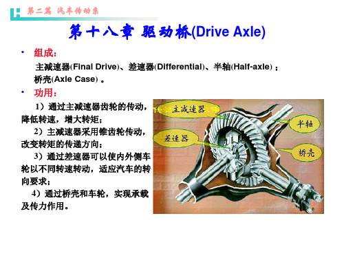
第二篇
汽车传动系
一、齿轮式差速器
为一行星齿轮系。行星架为输入端,中心轮、齿圈为2个输出端。将齿轮 变形后,就由不对称式变为对称式。
行星轮 行星架
中心轮 齿圈
• 类型:
圆锥齿轮式 圆柱齿轮式
对称式(等转矩式) 不对称式(不等转 矩式)
第二篇
汽车传动系
• 对称式锥齿轮差速器的结构与工作原理:
结构:差速器壳;行星齿轮;半轴齿轮;行星齿轮轴。 转矩传递路线:(1个输入端,2个输出端)
摩擦片式
最早被开发为产品,应用也最为广泛。
第二篇
汽车传动系
摩擦片自锁差速器
结构原理:
主、从动摩擦片分别与差速器壳和与 半轴相连的推力压盘连接。差速器壳带动 行星齿轮轴时,斜面将两轴分别向外推, 压紧摩擦片。
工作状况:
两侧车轮同速时: 摩擦片间无滑动。动力传动路线为: 差速器壳→行星轮轴→行星轮→半轴齿轮 →半轴 两侧车轮不同速时: 摩擦片间有滑动。摩擦力矩MT大。力 传动路线为: 差速器壳→行星轮轴→行星轮→半轴齿轮 →半轴摩擦片→推力压盘
能在必要时使汽车变成由单
侧车轮驱动,其锁紧系数为1, 明显提高了汽车的通过能力。此 外还具有工作可靠,使用寿命长 等优点。其缺点是左右车轮传递 转矩时,时断时续,引起车轮传 动装置中载荷的不均匀性和加剧
轮胎磨损。
第二篇
汽车传动系
第四节 变速驱动桥(transaxle)
驱动桥按其功能特点分又可分为独立式驱动桥和变速驱动桥。
圆柱齿轮式轮边减速器
半轴 轮毂
第二篇
汽车传动系
四、双速主减速器
具有两档传动比,以提高汽车的动力性和经济性。 有两级传动:锥齿轮传动、行星齿轮系传动。
驱动桥的英文词汇

差速器锁止机构 differential locking -device
差速器锁止系数 differential locking factor
差速器主齿轮轴 differential pinion-shaft
齿侧间隙 backlash in circular tooth
齿面接触区 circular tooth contact
锥齿轮齿数 number of teeth in bevel gears and hypoid gears
锥齿轮式差速器 bevel gear differential
自动离合式自锁差速器 automotive positive locking differential
总减速比 total reduction ratio
钢管扩张桥壳 expanded tube axle housing
格里林齿制 gleason tooth
贯通式驱动桥 tandem axles
贯通式主减速器 thru-drive
后置式双级主减速器 rear mounted double reduction final drive
平顶锥齿轮 contrate gear
平面锥齿轮 plane bevel gear
前置式双级主减速器 front mounted double reduction final drive
强制锁止式差速器 locking differential
桥壳 axle housing
驱动桥 drive axle(driving axle)
冲压焊接桥壳 press-welding axle housing
单级主减速器 single reduction final drive
汽车参考资料驱动桥的英语词汇
驱动桥的英语词汇前置式双级主减速器front mounted double reduction final drive 强制锁止式差速器locking differential桥壳axle housing驱动桥drive axle(driving axle)驱动桥额定桥荷能力rating axle capactiy驱动桥减速比driveaxle ratio驱动桥质量drive axle mass驱动桥最大附着扭矩slip torque驱动轴减速比axle ratio全浮式半轴full-floating axle shaft上置式双级主减速器top mounted double reducton final drive双级双速主减速器two speed double reduction final drive双级主减速器double reduction final drive双减速齿轮double reduction gear双铰接式摆动轴double joint swig axle双曲面齿轮hypoid gear双速主减速器two speed final drive四分之三浮式半轴three-quarter floating axle shaft凸轮滑滑块自锁差速器self-locking differential with side ring and radial cam plate外啮合圆柱齿轮式轮边减速器spur geared wheel reductor行星齿轮spider gear(planetary pinion)行星齿轮式双级主减速器planetary double reduction final drive 行星齿轮式双速主减速器two speed planetary final drive行星圆柱齿轮式轮边减速器planetary wheel reductor行星锥齿轮式轮边减速器differential geared wheel reductor(beve lepicyclick hub reductor)液压差速器hydraulic differential圆柱齿轮式差速器spur gear differential整体式桥壳banjo housing整体铸造式桥壳cast rigid axle housing轴间差速器interaxial differential主减速器final drive主降速齿轮final reduction gear主降速齿轮减速比final reduction gear ratio转向驱动桥steering drive axle锥齿轮齿宽face width of tooth in bevel gears and hypoid gear s锥齿轮齿数number of teeth in bevel gears and hypoid gears 锥齿轮式差速器bevel gear differential自动离合式自锁差速器automotive positive locking differential总减速比total reduction ratio组合式桥壳unitized carrier-type axle housing“三速”贯通轴"three-speed" tandem axles奥克托齿形octoid form奥林康型齿制oerlikon tooth半浮式半轴semi-floating axle shaft半轴axle shaft差速器differential差速器侧齿轮differential side gear差速器壳differential carrieer(case)差速器壳轴承carrier bearing差速器十字轴differential spider差速器锁止机构differential locking -device差速器锁止系数differential locking factor差速器主齿轮轴differential pinion-shaft齿侧间隙backlash in circular tooth齿面接触区circular tooth contact冲压焊接桥壳press-welding axle housing单级主减速器single reduction final drive单铰接式摆动轴single-joint swing axle单驱动桥single drive axle独立悬架式驱动桥independent suspension drive axle 断开式驱动桥divided axle锻压焊接桥壳forge welding axle housing对分式桥壳split housing多桥驱动multiaxle drive防滑式差速器limited -slip differential非独立悬架式驱动桥rigid drive axle钢管扩张桥壳expanded tube axle housing格里林齿制gleason tooth贯通式驱动桥tandem axles贯通式主减速器thru-drive后置式双级主减速器rear mounted double reduction final drive 减速器reducer可分式桥壳trumpet-type axle housing类型type轮边减速器wheel reductor(hub reductro)螺旋锥齿轮spiral bevel gear磨擦片式自锁差速器multi-disc self -locking differential平顶锥齿轮contrate gear平面锥齿轮plane bevel gear。
驱动桥汽车外文文献翻译、中英文翻译、外文翻译

Driving Axleautomobile driving axleThe driving axle is one of cross bars supporting a vehicle, on which the driving wheels turn .The driving axle includes a housing ,an axle drive ,a differential , tow axle shafts (half axles ),and final drives (if any ) .The axle .or main, drive is a drive-line unit that increases the torque delivered by the transmission and transmits it to the driving wheels, via the differential. In automobiles, the axle drive shaft, usually called the propeller shaft.The axle drive may be a Single or a double-stage type, the former comprising a pair of gears and the latter .tow pairs of gear. Drive pinion I may be made integral with its shaft, or it may be detachable from the shaft. Driving gears and are usually made in the form of detachable gear rings that are bolted or riveted to the differential case .Alex drive bevel pinions and gears are made with helical teeth in order to reduce noise in operation.The tow-stage axle drive consists of a pair of bevel gears and a pair of spur gears. Drive bevel pinion drives bevel gear that is fixed to the flange of the intermediate shaft made integral with 2nd–stage driving spur gear .Gears meshes with driven spur gear which is fastened to the case rotates in taper roller bearings installed in the differential carrier that makes part of the driving axle housing.The differential is a drive-line unit that divides the torque applied to it between the tow axle shafts and allows one driving wheel to turn at a different speed from the other.The differential consists of case, cross or spider pinion .and side gears, also known as axle gears .the differential pinions are freely mounted on the cylindrical arms of the spider, which is held in the differential case, and remain in constant mesh with the differential side gears.When the automobile is moving down a straight and even road, both driving wheels meet with one and the same rolling resistance. In this case, axle driven gear, or differential ring gear, causes the differential case to rotate .when the differential case rotates pinions and their spider arms move around in a circle with tow differential side gears are meshed with the pinions, the side gears must rotate, causing the axle shafts and their associated driving wheels to turn. With equal resistance applied to each wheel, the differential pinions do not rotate. They apply equal torque to the side gears and therefore both driving wheels rotate at one and the same speed is unequal ,the differential pinions rotate on their spider arms as well as drive round with the differential case .supposing that one of the axle shaft is prevented from rotating ,the differential pinions would have to walk around the stationary side gear ,causing the other side gear to rotate at twice its normal speed .You can now see how the differential can allow one driving wheel to turn faster than the other .Whenever the automobile goes around a turn ,the outer driving wheel travels a greater distance than the inner drive wheel .the inner wheel speeds up proportionately ,thanks to the differential pinions that rotate on their spider arms and ,rolling around the slower side gear send more rotary motion to the outside wheel.The differential side gears are splined on to the inner ends of the axle shafts .The other ends of the shafts are attached to the driving wheel hubs by means of flanges .Trucks use full floating axle shafts .Such axle shafts are acted upon by torque only .All the other loads acting on the driving wheels are taken by the driving axle housing, because the wheel hubs are supported by bearings mounted on the housing.Driving axle of general-purpose wheeled tractorGeneral-purpose wheeled tractors are a four-wheel drive type, they have tow driving axles-front and rear .Both axles are similar in construction, expect for the housing. Each driving axle consist if a housing, an axle drive ,a differential ,and final drives .The front and rear-axles drives are interchangeable and comprise a pair of spiral bevel gears . The axle drive pinion is made integral with a shaft that issupported by tow taper roller bearings installed in axle drive pinion carrier .The latter is accommodated in differential carrier and is fixed to it by bolts. The flange of the axle drive pinion carrier is provided with threaded holes to fit puller screws that are used to remove the axle drive pinion carrier from the differential carrier .The position of the drive pinion relative to the centerline of the axle is adjust by means of a pack of shims placed under the flange of the drive pinion carrier Shims palace under the cone of the front bearing are used to adjust the preload on the drive pinion bearings. Splined to adjust the preload on the drive pinion shaft is universal-joint flange .The axle drive gear is bolted to the differential case flange.THE DIFFERENTIAL consists of case, four pinions, and tow side gears .The differential case comprise tow halves that are bolted together and supported by taper roller bearings installed in the differential carrier .Screwed in the bearings housing from the outside are nuts used to adjust the backlash between the ring gear and drive pinion teeth and the side bearing preload.Welded to the top of the driving axle housing at both its ends are spring pads .The housing of both its ends are spring axels are provided with filler ,overflow ,and drain holes closed by plugs .Both housing also have vents ,The rotating components of the driving axles are lubricated with transmission oil .As distinct from the automobiles considered in this text, all tractors include final drives in their power trains .The final drives of general-purpose wheel tractors are referred to as wheel-hub reduction gears.While transmitting power to the driving wheels, wheel-hub reduction can increase their torque .These are planetary reduction gear sets consist of sun gear ,or wheel ,three planet ,or pinion ,gears ,planet or pinion ,carrier .stationary internal ,or ring ,gear ,and housing.The sun gear is splined to the outer end of the axle shaft is splined to the differential side gear .The cylindrical planet gears are in constant mesh with both the sun gear and the ring gear and are free to rotate on roller bearings mounted on shafts that are attached to the planet carrier .The planet carrier is fasted to the reduction gear housing by means of studs and nuts .The flange of housing ,driving wheel brake drum13,and wheel hub are clamped together by bolts .The planet carrier and reduction gear housing form the driven part of the planetary gear set and rotate with the driving wheel of the tractor .The driving gear hub is supported by taper roller bearings mounted on axle shaft housing ,or axle sleeve .The axle sleeve is connected to the stationary ring gear by means of adapter hub that has internal splines and external teeth . The splines are meshed with matching splines on the axle sleeve, and the teeth are meshed with internal teeth ring gear.Wheels and its maintainModern wheeled tractors and automobiles use pneumatic-tired disc wheels. As a result of the driving wheel tires gripping the road, the rotary motion of the wheels is transformed into the translational motion of the tractor or automobile.According to their purpose, wheels are classified as driving .driven steerable, and combination types.Trucks and general-purpose wheeled tractors have all their wheels of one and the same size .Row-crop tractors have their rear wheels larger than the front wheels .The rear wheels carry the major proportion of the load due to the weight of the tractor .The front wheels are loaded lighter and this makes them easier to turn and provide good directional steering stability, which is essential for row-crop work.A TRUCK WHEEL consists of disc and flat base rim that is made integral with it, while the other flange is formed by detachable side ring that is held to the rim by split lock ring on the rim .which doubles as a side ring and a lock ring.The wheel disc is provided with holes for mounting the wheel on the wheel mounting bolts ,or wheel studs ,on the wheel hub ,where it is fixed by nuts .Both the holes and the nuts are tapered to ensure exact location of the wheel on its hub .The rear driving axles of trucks carry tow wheels at each end .The inner wheels are held to the hubs by cap nuts that are threaded both on the inside and on the outside .and the outer wheels are mounted on the cap nuts and fixed in place by taper nuts screwed on the nuts .The wheel nuts on the right side of truck have right-hand threads, whereas the nuts on the left side of the truck are threaded left-hand .The reason is to tighten the nuts, not loosen them, and thus prevent them from working loose on acceleration andbraking.An automobile pneumatic tire consists of casing, inner tube, and flap .The tire casing comprises tread, side walls, and beads .Tires for good roads use small tread patterns, while those for bad roads or cross –country service large tread patterns.The inner tube is made in the form of a hollow elastic rubber doughnut that is inflated with air after it is installed inside the tire and the tire is put on the wheel rim .The inner tube is inflated through tire valve that consists of housing 11,valve inside ,and cap .The valve housing is made of brass in the dorm of a flanged tube that is mounted in the inner tube by means of a washer and a nut and sticks out through a hole in the wheel .Some tire valve housing are of comprise construction :the upper part is made of brass and the lower part ,of rubber that is vulcanized on to the inner tube .The valve inside is a check valve that opens to let air in the inner tube when an air closed ,spring pressure and air pressure inside the tube hold the valve .When the valve is closed ,spring pressure and air pressure inside the tube hold the valve in its seat .It includes core with a rubber ring ,a plunger pin ,and a spring .The valve inside is Screwed in the tire valve housing and is closed by the cap Screwed on the housing.To the construction of the driving and steerable wheels, each wheel comprises hub , disc with rim ,and tire with inner tube .The rim is welded to the disc and the disc is bolted to the hub .The driving wheel tires are of low-pressure type and have heavy tread bars for better traction.The driving wheel hub is keyed to axle shaft and is fixed in place by means of bolted-on insert with worm whose threads mesh with the rack teeth cut in the half axle .By turning the worm one can change the position of the wheel on the axle shaft to obtain the desired track width .Before doing this ,it is necessary to jack up the rear part of the tractor to clear the wheels of the ground and loosen the bolts that hold the inserts to the wheels hubs .Should this adjustment prove insufficient ,the track width can further be increased by placing the wheels with the concaves of their discs facing inwards.On some row-crop tractors ,the rear wheel discs are bolts to lugs welded on the wheel rims .In this case ,the crack width can be changed by bolts the discs in alternative positions to the lugs .Also the concave wheel discs may be used either with the concave facing inwards or outwards.Trouble-free operation of automobiles and wheeled tractors largely depends on the condition of the tires. Therefore, during operation, one should adhere to following rules.Prevent fuel and, or oil from getting onto the tires. Cleans the tires regularly from dirt and remove all foreign articles, such as stones, form the treads. Do not apply brakes sharply, never start away form rest with a jerk, and avoid making sharp turns, for all this causes uneven wear of the tires. Do not allow excessive slipping of the driving wheels. When preparing your tractor or automobile for a long-term storage, jack up the wheels and put trestles under the axles or frame to relieve the tires.The service life of tires is expressed in terms of their mileage. For most bias (ordinary) truck tires, the guaranteed mileage amounts to 50000 km. Observing the above rules will help prolong the useful service life of tires.驱动桥汽车的驱动桥驱动桥是一个支撑车辆的十字交叉的轴,它可以驱动车轮运动。
驱动桥汽车外文文献翻译、中英文翻译、外文翻译
驱动桥汽车外文文献翻译、中英文翻译、外文翻译The driving axle is an essential component of a ___。
It consists of several parts。
including a housing。
axle drive。
differential。
two axle shafts。
and final drives if necessary.The main purpose of the axle drive is to ___。
___.There are two types of axle drives: single and double-stage。
The single-stage type has a pair of gears。
while the double-stage type has two pairs of gears。
The drive ___ case。
To ce noise during n。
axle drive ___.In summary。
___。
It includes several components that work ___ to the wheels。
The axle drive shaft is an essential part of the axle drive。
and there are two types of axle drives。
To ce noise during n。
the driving gears are made with ___.When a car turns。
___ a greater distance than the inner ___。
thanks to the differential ns ___ around the slower side gear。
the inner ___。
驱动桥5000字外文翻译文献
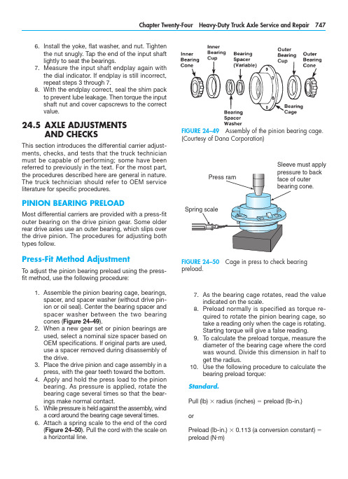
As the bearing cage rotates, read the value7. indicated on the scale.Preload normally is specified as torque re-8. quired to rotate the pinion bearing cage, so take a reading only when the cage is rotating. Starting torque will give a false reading.To calculate the preload torque, measure the 9. diameter of the bearing cage where the cord was wound. Divide this dimension in half to get the radius.10. U se the following procedure to calculate thebearing preload torque:Standard.Pull (lb) 3 radius (inches) 5 preload (lb-in.)orPreload (lb-in.) 3 0.113 (a conversion constant) 5 preload (N .m)Install the yoke, flat washer, and nut. Tighten 6. the nut snugly. Tap the end of the input shaft lightly to seat the bearings.Measure the input shaft endplay again with 7. the dial indicator. If endplay is still incorrect, repeat steps 3 through 7.With the endplay correct, seal the shim pack 8. to prevent lube leakage. Then torque the i nput shaft nut and cover capscrews to the correct value.24.5 A XLE ADJUSTMENTSAND CHECKSThis section introduces the differential carrier adjust-ments, checks, and tests that the truck technician must be capable of performing; some have beenr eferred to previously in the text. For the most part, the procedures described here are general in nature. The truck technician should refer to OEM servicel iterature for specific procedures.PINION BEARING PRELOADMost differential carriers are provided with a press-fit outer bearing on the drive pinion gear. Some older rear drive axles use an outer bearing, which slips over the drive pinion. The procedures for adjusting both types follow.Press-Fit Method AdjustmentTo adjust the pinion bearing preload using the press-fit method, use the following procedure:Assemble the pinion bearing cage, bearings, 1. spacer, and spacer washer (without drive pin-ion or oil seal). Center the bearing spacer and spacer washer between the two bearing cones (Figure 24–49).When a new gear set or pinion bearings are 2. used, select a nominal size spacer based on OEM specifications. If original parts are used, use a spacer removed during disassembly of the drive.Place the drive pinion and cage assembly in a 3. press, with the gear teeth toward the bottom.Apply and hold the press load to the pinion 4. bearing. As pressure is applied, rotate the bearing cage several times so that the bear-ings make normal contact.While pressure is held against the assembly, wind 5. a cord around the bearing cage several times.Attach a spring scale to the end of the cord 6. (Figure 24–50). Pull the cord with the scale ona horizontal line.FIGURE 24–49 Assembly of the pinion bearing cage.(Courtesy of Dana Corporation)FIGURE 24–50 Cage in press to check bearingp reload.Sleeve must applymust be against the outer bearing. If the fit between the yoke or flange splines and drive pinion splines is tight, use a press to install the yoke or flange (Figure 24–51).Temporarily install the drive pinion and cage 4. assembly in the carrier (Figure 24–52). Do not install shims under the bearing cage.Install the bearing cage to the carrier cap-5. screws. Washers are not required at this time. Hand-tighten the capscrews.Fasten a yoke or flange bar to the yoke or 6. flange (Figure 24–53). The bar will hold the drive pinion in position when the nut ist ightened.Metric.Pull (kg) 3 radius (cm) 5 preload (kg-cm) orPreload (kg-cm) 3 0.098 (a conversion constant) 5 preload (N .m)Examples. We can convert the foregoing equa-tions into examples by applying some data to them:Standard7.5 lb 3 3.31 in. 5 24.8 lb-in. (preload) or24.8 lb-in. 3 0.113 5 2.8 N .m (preload)Metric3.4 kg 3 8.4 cm 5 28.6 kg-cm (preload) or28.6 kg-cm 3 0.098 5 2.8 N .m (preload)11. I f necessary, adjust the pinion bearing preloadby changing the pinion bearing spacer. A thicker spacer will decrease preload, whereas a thinner spacer will increase the preload.12. O nce the correct bearing preload has beenestablished, note the spacer size used. Select a spacer 0.001 inch (0.025 mm) larger for use in the final pinion bearing cage assembly pro-cedures. The larger spacer compensates for slight expansion of the bearing, which occurs when pressed on the pinion shank. The trial spacer pack should result in correct pinion bearing preload in three times out of four cases.Y oke Method of AdjustmentTo adjust the pinion bearing preload using the yoke or flange method, proceed as follows:Assemble the complete pinion bearing cage 1. as recommended in the press-fit method.A forward axle pinion is equipped with a heli-2. cal gear. For easier disassembly during bear-ing adjustment procedures, use a dummy yoke (if available) in place of the helical gear.Install the input yoke or flange, nut, and 3.washer on the drive pinion. The yoke or flangeFIGURE 24–51 Using a press to install the yoke orflange to the drive pinion. (Courtesy of Arvin Meritor)FIGURE 24–52 Install the pinion and cage assembly in the carrier housing. (Courtesy of Arvin Meritor)indicated on the torque wrench (see Figure 24–55). Typical value is 50 lb-ft. (68 N .m)m aximum applied to one side gear.If the torque value exceeds the specification, 5. disassemble the differential gears from the case halves.Check the case halves, spider, gears, and 6. thrust washers for the problem that caused the torque value to exceed specifications. Re-pair or replace defective parts as required. Remove any foreign debris.Check/Adjust Pinion Cage Shim PackThis procedure is used to check and adjust the thick-ness of the shim pack used in the pinion bearing cage. Use this procedure if a new drive pinion and crownTighten the nut on the drive pinion to specifi-7. cation, typically 400 to 700 lb-ft. (542 to 950 N .m).Remove the yoke or flange bar.8. Attach a torque wrench to the drive pinion 9. nut. Rotate the drive pinion and read the value indicated on the torque wrench. Preload is correct when the torque required to rotate the pinion bearing cage is from 15 to 35 lb-in. (1.7 to 4.0 N .m).To adjust the pinion bearing preload, disas-10. semble the pinion bearing cage and change the pinion bearing spacer size. A thicker spacer will decrease preload, whereas a thin-ner spacer will increase preload.Differential Rolling ResistanceA check to measure and establish differential rolling resistance follows. To perform this check, a special tool must be made. You can easily make this tool from an old axle shaft that matches the spline size of the differential side gear. Figure 24–54 illustrates the fab-rication specifications for this special tool.To check differential resistance to rotation, use the following procedure:Install soft metal covers over the vise jaws to 1. protect the ring gear (Figure 24–55).Place the differential and crown gear assem-2. bly in the vise.Install the special tool into the differential until 3. the splines of the tool and one side gear are engaged.Attach a torque wrench to the nut of the spe-4. cial tool and rotate the differential gears. As the differential gears rotate, read the valueFIGURE 24–55 Reading the torque value to check the rolling resistance. (Courtesy of Arvin Meritor)FIGURE 24–53 Using a flange bar to hold the drivepinion in position. (Courtesy of Arvin Meritor)FIGURE 24–54 Fabrication details for a tool to checkthe rolling resistance. (Courtesy of Arvin Meritor)If the new pinion cone number is a minus (–), sub-8. tract the number from the standard shim packthickness that was calculated in step 3 or 4.The value calculated in step 7 or 8 is the 9.t hickness of the new shim pack that will bei nstalled. Figure 24–59 illustrates several e xamples of determining shim pack t hickness.Install the drive pinion, bearing cage, and new10. shim pack into the differential carrier.gear set is to be installed, or if the depth of the drive pinion has to be adjusted. You are checking the rolling resistance using a torque wrench.To check/adjust the shim pack thickness (Figure 24–56), do the following:With a micrometer, measure the thickness of 1. the old shim pack removed from under the pinion cage (Figure 24–57). Record the mea-surement for later use.Look at the pinion cone (PC) variation number 2. on the drive pinion being replaced (Figure 24–58). Record this number for later use also.If the old pinion cone number is a plus (+), 3. subtract the number from the old shim pack thickness that was recorded in step 1.If the old pinion cone number is a minus (–), 4. add the number to the old shim thickness that was measured in step 1.The value calculated in step 3 or 4 is the 5.t hickness of the standard shim pack without variation.Look at the PC variation number on the new 6. drive pinion that will be installed. Record the number for later use.If the new pinion cone number is a plus (+), 7. add the number to the standard shim packthickness that was calculated in step 3 or 4.FIGURE 24–56 Drive pinion depth controlled by shimpack thickness. (Courtesy of Arvin Meritor)FIGURE 24–57 Measuring the thickness of the old shim pack. Mike each shim individually then add tocalculate total thickness. (Courtesy of Arvin Meritor)FIGURE 24–58 Location of the pinion cone (PC)v ariation number. (Courtesy of Arvin Meritor)Adjust Differential Bearing PreloadOne of two methods can be used to check and adjust the preload of the differential bearings.Method One.Attach a dial indicator onto the mounting 1. flange of the carrier and adjust the indicator so that the plunger rides on the back surface of the crown ring gear (Figure 24–60).Loosen the bearing adjusting ring that is op-2. posite the ring gear so that a small amount of endplay is indicated on the dial indicator. To turn the adjusting rings, use a T-bar wrench that engages two or more opposite notches in the ring (Figure 24–61).Move the differential and crown gear to the 3. left and right using prybars as you read the dial indicator. Use two prybars that fit be-tween the bearing adjusting rings and the ends of the differential case (Figure 24–62). You also can use two prybars between the differential case or crown gear and the carrier at locations other than those just described. In either case, the prybars must not touch the differential bearings.EXAMPLES:Inchesmm 1.Old Shim Pack Thickness Old PC Number, PC +2Standard Shim Pack Thickness New PC Number, PC +5New Shim Pack Thickness .030.76–.002–.05.028.71+.005+.13.033.842.Old Shim Pack Thickness Old PC Number, PC –2Standard Shim Pack Thickness New PC Number, PC +5New Shim Pack Thickness .030.76+.002+.05.032.81+.005+.13.037.943.Old Shim Pack Thickness Old PC Number, PC +2Standard Shim Pack Thickness New PC Number, PC –5New Shim Pack Thickness .030.76–.002–.05.028.71–.005–.13.023.584.Old Shim Pack Thickness Old PC Number, PC –2Standard Shim Pack Thickness New PC Number, PC –5New Shim Pack Thickness.030.76+.002+.05.032.81–.005–.13.027.68FIGURE 24–59 Determining shim pack thickness.(Courtesy of ArvinMeritor Inc.)FIGURE 24–60 Dial indicator attached to carrier-mounted flange. (Courtesy of Arvin Meritor)FIGURE 24–61 Turning the adjusting ring using aT-bar wrench. (Courtesy of Arvin Meritor)FIGURE 24–62 Using pry bars to adjust play in the crown gear. (Courtesy of Arvin Meritor)Tighten the same bearing adjusting ring4.so that no endplay shows on the diali ndicator.Move the differential and crown gear to the5.left and right as needed. Repeat step 3 untilzero endplay is achieved.Tighten each bearing adjusting ring one6.notch from the zero endplay measured instep 4.Method Two.A second method of checking pre-load is to measure the expansion between the bearing caps after you tighten the adjusting rings. Use the following procedure:Turn both adjusting rings hand tight against1.the differential bearings.Measure the distance X or Y between oppo-2.site surfaces of the bearing caps (Figure24–63A) using a large micrometer of thec orrect size (Figure 24–63B). Make a note ofthe m easurement.Tighten each bearing adjusting ring one3.notch.Measure the distance X or Y again. Compare4.the dimension with the distance X or Y mea-sured in step 2. The difference between thetwo dimensions is the amount that the bear-ing caps have expanded.Example: Measurements of a carrier.Distance X or Y before tightening adjusting rings5 15.315 inches (389.00 mm)Distance X or Y after tightening adjusting rings5 15.324 inches (389.23 mm)15.324 inches minus 15.315 inches5 0.009 inch (0.23 mm) differenceIf the dimension is less than specification, repeat steps 3 and 4 as needed.Crown Gear Runout CheckTo check the runout of the crown/ring gear, do the f ollowing:Attach a dial indicator on the mounting flange1.of the differential carrier (Figure 24–64).Adjust the dial indicator so that the plunger or2.pointer is against the back surface of thecrown gear.FIGURE 24–63 (A) Location of distances measured to check expansion between bearing caps aftert ightening adjusting rings; (B) measuring this distance.(Courtesy of Arvin Meritor)FIGURE 24–64 Checking crown gear runout. (Courtesy of Arvin Meritor)Pinion and Crown Tooth ContactA djustment Correct tooth contact between the pinion and crown gear cannot be overemphasized, because improper tooth contact results in noisy operation and prema-ture failure. The tooth contact pattern consists of the lengthwise bearing (along the tooth of the ring gear) and the profile bearing (up and down the tooth). F igure 24–68 shows crown gear toothn omenclature.Adjust the dial of the indicator to zero.3. Rotate the differential and crown gear when4. reading the dial indicator. The runout of the crown gear must not exceed 0.008 inch (2 mm) (a typical value; refer to the applicable OEM service literature for the specificv alues).If runout of the crown gear exceeds the speci-5. fication, remove the differential and crown gear assembly from the carrier. Check the dif-ferential components, including the carrier, for the problem causing the runout of the gear to exceed specification. Repair or replace defec-tive components.After the components are repaired or re-6. placed, install the differential and crown gear into the carrier.Repeat the preload adjustment of the 7. differential bearings. Then repeat this runout procedure.Check/Adjust Crown Gear BacklashIf the used crown and pinion gear set is installed, ad-just the backlash to the setting that was measured before the carrier was disassembled. If a new gear set is to be installed, adjust backlash to the correct speci-fication for the new gear set.To check and adjust ring gear backlash, do thef ollowing: Attach a dial indicator onto the mounting1. flange of the carrier (see Figure 24–64).Adjust the dial indicator so that the plunger is 2. against the tooth surface at a right angle.Adjust the dial of the indicator to zero, making 3. sure that the plunger is loaded through at least one revolution.Hold the drive pinion in position.4. When reading the dial indicator, rotate the5. crown gear a small amount in both directions against the teeth of the drive pinion (Figure 24–65). If the backlash reading is not within specification (typically ranging from 0.010 to 0.020 inch or 254 to 508 mm), adjust backlash as outlined in steps 6 and 7.Loosen one bearing adjusting ring one notch 6. and then tighten the opposite ring the same amount. Backlash is increased by moving the crown gear away from the drive pinion (Figure 24–66). Backlash is decreased by moving the crown gear toward the drive pin-ion (Figure 24–67).Repeat steps 2 through 5 until the backlash is 7.within specifications.FIGURE 24–65 Check crown gear backlash. ( Courtesy of Arvin Meritor)FIGURE 24–66 Adjustments to increase backlash. (Courtesy of Arvin Meritor)the pattern in an unloaded condition (such as when you are performing this test) will be approximately one-half to two-thirds of the crown gear tooth in most models and ratios.Checking Tooth Contact Pattern on a Used Gear Set. Used gearing will not usually display the square, even contact pattern found in new gear sets. The gear will normally have a pocket at the toe-end of the gear tooth (Figure 24–71) that tails into a contact line along the root of the tooth. The more use a gear has had, the more the line becomes the dominant characteristic of the pattern.Adjusting Tooth Contact Pattern. When dis-assembling, make a drawing of the gear tooth con-tact pattern so that when reassembling it is possible to replicate approximately the same pattern. A cor-rect pattern should be clear of the toe and centers evenly along the face width between the top land and the root. Otherwise, the length and shape of the pattern can be highly variable and are usually con-sidered acceptable—providing the pattern does not run off the tooth at any time. If necessary, adjust the contact pattern by moving the crown gear and drive pinion.Checking Tooth Contact Pattern on a New Gear Set. Paint 12 crown gear teeth with a marking compound (Figure 24–69) and roll the gear to obtain a tooth contact pattern. A correct pattern should be well centered on the crown gear teeth with lengthwise contact clear of the toe (Figure 24–70). The length ofFIGURE 24–67 Adjustments to decrease backlash.(Courtesy of Arvin Meritor)FIGURE 24–68 Crown gear tooth nomenclature.(Courtesy of Dana Corporation)FIGURE 24–69 Application of a marking compoundto check tooth contact. (Courtesy of Dana Corporation)FIGURE 24–70 Correct tooth contact patternfor new gearing. (Courtesy of Dana Corporation)FIGURE 24–71 Correct tooth contact pattern for used gearing. (Courtesy of Dana Corporation)making adjustments, first adjust the pinion and then the backlash. Continue this sequence until the pattern is satisfactory.Thrust Screw AdjustmentFor those differential carriers equipped with a thrust screw, perform the following procedure. (If the carrier assembly does not have a thrust block, proceed to step 4 of this procedure.)Rotate the carrier in the repair stand until the 1. back surface of the crown gear is toward the top.Put the thrust block on the back surface of 2. the ring gear. The thrust block must be in the center between the outer diameter of the gear and the differential case.Rotate the crown gear until the thrust block 3. and hole for the thrust screw, in the carrier, are aligned.Install the jam nut on the thrust screw, one-4. half the distance between both ends (Figure 24–74).Install the thrust screw into the carrier until the 5. screw stops against the crown gear or thrust block.Loosen the thrust screw one-half turn, or 180 6. degrees.Tighten the jam nut to the correct torque value 7. against the carrier (typical values range from 150 to 295 lb-ft. or 200 to 400 N .m) (Figure 24–75).Axle TrackingAxle tracking can be measured using the older tram bar method or electronic alignment equipment. The procedures for setting axle alignment and tracking areexplained in Chapter 25.FIGURE 24–72 Two incorrect patterns when adjusting pinion position. (Courtesy of Dana Corporation)Crown gear position controls the backlash setting. This adjustment also moves the contact pattern along the face width of the gear tooth (Figure 24–72). Pinion position is determined by the size of the pinion bear-ing cage shim pack. It controls contact on the tooth depth of the gear tooth (Figure 24–73).These adjustments are interrelated. As a result, they must be considered together even though thepattern is altered by two distinct operations. WhenFIGURE 24–73 Two incorrect patterns when adjusting backlash. (Courtesy of Dana Corporation)• Most differential carriers are replaced as rebuilt/exchange units, so the role of the technician is, more often than not, to diagnose the problem and then, if necessary, to replace the defective assembly as a unit.• The technician who has disassembled and reas-sembled differential carriers should find trouble-shooting procedures easier to follow.• Follow the OEM procedure when disassem-bling differential carriers. Taking a few mo-ments to measure shim packs and gear tooth contact patterns on disassembly can save considerable time when reassembling thec arrier.• A crown and pinion gear set often can ber eused when rebuilding a differential carrier. Make sure that you inspect it properly ond isassembly.• Crown and pinion gear sets are always replaced as a matched pair during a rebuild.• When setting crown and pinion backlash, it is increased by moving the crown gear away from the drive pinion and decreased by moving the crown gear toward the drive pinion.• Adhering to OEM-recommended lubrication schedules is the key to ensuring the longest service life from both drive and dead axles.• Knowing the correct procedure to check lubricant level is essential. The level is correct when lubri-cant is exactly level with the bottom of the fill hole.• Because most OEMs approve of the use of syn-thetic lubricants in final drive carriers, lubrication drain schedules have been greatly increased in recent years. Drain schedules are determined by the actual lubricant used and the type of appli-cation to which the vehicle is subjected.• Servicing of axles on heavy-duty trucks consists of routine inspection, lubrication, cleaning, and, when required, troubleshooting and component overhaul.• Failure analysis is required to prevent recurrent failures.• Drive axle carrier components usually fail for one of the following reasons: Shock load Fatigue Spinout Lubrication problemsNormal wearFIGURE 24–74 Installing the jam nut on the thrust screw. (Courtesy of Arvin Meritor)FIGURE 24–75 Tighten the jam nut to the correct torque value. (Courtesy of Arvin Meritor)SUMMARY。
文献翻译:驱动桥
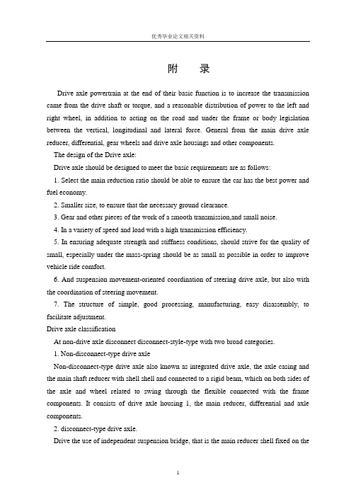
附录Drive axle powertrain at the end of their basic function is to increase the transmission came from the drive shaft or torque, and a reasonable distribution of power to the left and right wheel, in addition to acting on the road and under the frame or body legislation between the vertical, longitudinal and lateral force. General from the main drive axle reducer, differential, gear wheels and drive axle housings and other components.The design of the Drive axle:Drive axle should be designed to meet the basic requirements are as follows:1. Select the main reduction ratio should be able to ensure the car has the best power and fuel economy.2. Smaller size, to ensure that the necessary ground clearance.3. Gear and other pieces of the work of a smooth transmission,and small noise.4. In a variety of speed and load with a high transmission efficiency.5. In ensuring adequate strength and stiffness conditions, should strive for the quality of small, especially under the mass-spring should be as small as possible in order to improve vehicle ride comfort.6. And suspension movement-oriented coordination of steering drive axle, but also with the coordination of steering movement.7. The structure of simple, good processing, manufacturing, easy disassembly, to facilitate adjustment.Drive axle classificationAt non-drive axle disconnect disconnect-style-type with two broad categories.1. Non-disconnect-type drive axleNon-disconnect-type drive axle also known as integrated drive axle, the axle casing and the main shaft reducer with shell shell and connected to a rigid beam, which on both sides of the axle and wheel related to swing through the flexible connected with the frame components. It consists of drive axle housing 1, the main reducer, differential and axle components.2. disconnect-type drive axle.Drive the use of independent suspension bridge, that is the main reducer shell fixed on thevehicle chassis, on both sides of the axle and wheel in the horizontal plane as opposed to relative movement of the body is referred to as drive off the bridge.In order to match with independent suspension, the main reducer shell fixed at the frame (or body), the drive axle housing sub connected through the hinge, or in addition to the main reducer shell outside the shell is no longer driven to other parts of the bridge. Wheel in order to meet the needs of independent jump up and down, between the differential and the wheel axle of the above connection between the use of universal joints.Drive axle componentsDriven mainly by the main bridge reducer, differential, axle and drive axle housings and other components.1. Main reducer assemblyUsed to change the main drive reducer general direction, to reduce speed and increase torque, and ensure there is sufficient car drivers and the appropriate speed skin. More types of the main reducer, a single-stage, dual-class, two-speed, such as Wheel Speed Reducer. 1) single-stage main reducerReduction gear by a slowdown in the realization of the devices, called single-stage reducer. Its structure is simple, light weight, such as Dongfeng BQl090 type light and medium-sized trucks on a wide range of applications.2) two-stage main reducerLarger number of heavy-duty trucks, require a larger reduction ratio, the main use of a single-stage reducer drive, moving from gear to be larger in diameter will affect the drive axle of the ground clearance, so the use of two slowdown. Often referred to as two-stage reducer. There are two sets of two-stage reduction gear reducer, speed the realization of the two by twisting.In order to enhance the meshing gear pair taper and strength of a smooth, slow down the first-class pair of spiral bevel gear is. Gears 2 is inclined gear teeth due to prop.Take the initiative to rotate bevel gear, gear driven rotary driven round silver, thus completing a slowdown. Active second stage cylindrical gear reducer and the driven bevel gear coaxial with the rotation, and drive gear driven rotating cylinder, a second-class speed. Due to the driven gear mounted on the cylindrical shell on the differential, so that when the driven gear rotating cylinder, through the differential and drive axle that is, the rotation of the wheels.2. DifferentialDifferential is designed to connect the axle around, on both sides of the wheels can rotate at different angular torque transfer at the same time. To ensure the normal scroll wheel. Some multi-bridge-driven cars, in the sub-actuator type or in the transmission through the shaft is also equipped with a differential, known as the bridge between the differential. Its role is to turn in the car or on uneven road surface, so that drive wheels before and after the differential between the role.At present, China-made cars and other types of vehicles in the basic use of symmetric ordinary differential bevel gear. Symmetric by the planetary bevel gear differential gear, axle gears, planetary gear axis (cross-axis or a direct-axis) and the differential composition of the shell and so on.At present the majority of planetary gear-type motor vehicles using differential and ordinary differential bevel gear cone by two or four planet gears, planetary gear shaft, the two cone axle differential gear, and about the composition of the shell and so on.3.Auto semi-axleAxle is the differential torque and then came to the wheels, drive wheels spin, promote the solid axle car. As a result of the installation of wheel structure, and the forces of the axle are also different. Therefore, divided into full-floating axle, semi-floating, 3 / 4, three types of floating.1) full-floating axleGenerally large and medium-sized used car floating the whole structure. Axle with the inner end of the spline axle with the differential gear connected to the outer end of the axle forging a flange with bolts and wheel hub to connect. Wheel away from the more distant of two tapered roller bearings for the text on the axle casing. Rear axle shell casing pressure and one pair to form the drive axle housing. Supporting the use of such forms, axle and axle housing no direct link so that only bear the drive axle torque without bearing any moment, the axle referred to as "full-floating" axle. The so-called "floating", meaning not subject to bending load axle.Full-floating axle, the outer end flange plate for one made with the axis. But there are also a number of trucks to make a separate flange parts, and by nested spline outer end in the axle. Thus, at both ends of the axle spline, you can use for the first.2) semi-floating axleSemi-floating axle with the inner end of the same floating, not subject to bending and torsion. Away from direct client support through a bearing in the axle of the inner shell. This approach will support the outer end axle bearing moment. Therefore, this short-sleeve in addition to transfer torque, but also to sustain the local moment, it is known as the semi-floating axle. This structure is mainly used in small passenger cars.License Hongqi CA7560 icon for the type of drive axle limousine. Axle from the inner end of its moment, out client has to bear all the moment, so called semi-floating bearing. 3) 3 / 4 floating axle3 /4 floating axle is affected by the degree of bending between the short semi-floating and full floating between. At present the application of this type halfshaft few pickup truck only on individual applications such as Warsaw, M20 vehicles.4. Automobile axle housing:1) the overall shell-style bridgeBridge shell due to the overall strength and stiffness performance, ease of main reducer installation, adjustment and maintenance, and are widely used. Integral axle housing due to different manufacturing methods can be divided into the overall foundry type, pressed into the middle of casting steel pipe and welded steel plate, such as stamping.2) sub-type drive axle housingSub-type axle housing will generally be divided into two sections, from two sections of a connecting bolt. Sub-type axle housing casting and processing easier.驱动桥处于动力传动系的末端,其基本功能是增大由传动轴或变速器传来的转矩,并将动力合理的分配给左、右驱动轮,另外还承受作用于路面和车架或车身之间的垂直立、纵向力和横向力。
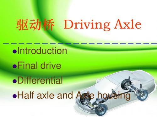
驱动桥 Driving Axle
Classification :
Banjo housing
Unitized housing
驱动桥 Driving Axle
Introduction Final
drive
Differential
Half
axle and Axle housing
Introduction
Function : To lower the speed and torque that come from the universal joint, then distribute the power to the drive wheel. Composition: Axle housing Final drive Differential
half axle
Axle housing
Function:
To fix the final drive, differential, half axle, wheel hub all together as bedrock.
linker
locknut wheel hub half axle HongQi7560
转弯行驶时的差速器
1. 对称式锥齿轮差速器工作原理
Principle:
Steering on line:
n1=n2=nk
n1+ n2 =2nk
Differential lock
Full locking differential
Self-locking Differential
在两半轴转速不等时,行星齿轮自转,差速器所 受摩擦力矩与快转半 轴旋向相反,与慢转 半轴旋向相同,故能 够自动地向慢转一方 多分配一些转矩。
- 1、下载文档前请自行甄别文档内容的完整性,平台不提供额外的编辑、内容补充、找答案等附加服务。
- 2、"仅部分预览"的文档,不可在线预览部分如存在完整性等问题,可反馈申请退款(可完整预览的文档不适用该条件!)。
- 3、如文档侵犯您的权益,请联系客服反馈,我们会尽快为您处理(人工客服工作时间:9:00-18:30)。
驱动桥设计随着汽车对安全、节能、环保的不断重视,汽车后桥作为整车的一个关键部件,其产品的质量对整车的安全使用及整车性能的影响是非常大的,因而对汽车后桥进行有效的优化设计计算是非常必要的。
驱动桥处于动力传动系的末端,其基本功能是增大由传动轴或变速器传来的转矩,并将动力合理地分配给左、右驱动轮,另外还承受作用于路面和车架或车身之间的垂直力力和横向力。
驱动桥一般由主减速器、差速器、车轮传动装置和驱动桥壳等组成。
驱动桥作为汽车四大总成之一,它的性能的好坏直接影响整车性能,而对于载重汽车显得尤为重要。
驱动桥设计应当满足如下基本要求:1、符合现代汽车设计的一般理论。
2、外形尺寸要小,保证有必要的离地间隙。
3、合适的主减速比,以保证汽车的动力性和燃料经济性。
4、在各种转速和载荷下具有高的传动效率。
5、在保证足够的强度、刚度条件下,力求质量小,结构简单,加工工艺性好,制造容易,拆装,调整方便。
6、与悬架导向机构运动协调,对于转向驱动桥,还应与转向机构运动协调。
智能电子技术在汽车上得以推广使得汽车在安全行驶和其它功能更上一层楼。
通过各种传感器实现自动驾驶。
除些之外智能汽车装备有多种传感器能充分感知交通设施及环境的信息并能随时判断车辆及驾驶员是否处于危险之中,具备自主寻路、导航、避撞、不停车收费等功能。
有效提高运输过程中的安全,减少驾驶员的操纵疲劳度,提高乘客的舒适度。
当然蓄电池是电动汽车的关键,电动汽车用的蓄电池主要有:铅酸蓄电池、镍镉蓄电池、钠硫蓄电池、钠硫蓄电池、锂电池、锌—空气电池、飞轮电池、燃料电池和太阳能电池等。
在诸多种电池中,燃料电池是迄今为止最有希望解决汽车能源短缺问题的动力源。
燃料电池具有高效无污染的特性,不同于其他蓄电池,其不需要充电,只要外部不断地供给燃料,就能连续稳定地发电。
燃料电池汽车(FCEV)具有可与内燃机汽车媲美的动力性能,在排放、燃油经济性方面明显优于内燃机车辆。
这项发明通常涉及到多能源动力总成的车辆,以及,尤其是多能源动力总成,有多个电源包括电动马达来驱动的汽车轮子。
混合动力电动动力系统已经被发展成为包括电机(IC)做内燃机引擎,自主经营的或者联合根据行驶条件下,国家费用的牵引电池,与电源,最有效地满足当前所产生的电力需求车辆操作。
大部分电子混合动力汽车可以在市场上买到是前轮驱动车辆,只不过前轮带动起来的。
混合动力电动动力系统被开发用于四轮驱动车,允许两个电机和引擎传送权力后方的驱动轮。
当包装电动马达驱动后桥机组是较好的使用躺轴功率流,马达驱动单元被放在后桥中心线。
这样的电的混合动力系统,然而,现在的包装设计很困难,特别是当副轴车辆传动是用来传输动力,纵向驱动轴后轴。
需要混合动力电动存在的动力,在其中轴是靠电动机驱动的或的内燃机结合电机。
以减少成本,电动机器将提供所有混合功能,包括电气能源的产生、电动汽车、电子发动机启动投放市场,提高发动机的功率,再生式制动。
一个驱动器单位是混合动力电动汽车包括发动机,电动机器包括转子,副轴,齿轮组包括一个输入可驱动的连接到发动机和输出,用来传送之间权限投入与产出和生产第一速度微分导致一个录入速度超过每小时的速度输出,第一和第二驾车轴差动机构可驱动的连接到输出线时,因为传输功率和输出之间驾车轴,可驱动的行星齿轮装置连接到输出和转子,说之间权限传输转子和输出线,制作了第二速度微分导致转子速度超过速度输出。
转矩反应为减速的行星齿轮传动提供关于住房通过鼓轴或孔中,而不是通过一个外径住房,从而简化轴承支撑要求和允许紧凑的定位的机械传动的元素。
使用的行星齿轮传动将车速元素的电机驱动电只准许路径的尺寸缩小包装驱动单元所需的空间。
标准的适用范围就变得更加明显的优选从以下的详细描述,索赔和图纸。
要理解,的描述和明确的例子,虽然指示优先考虑的重要体现,给出了发明的说明而已。
各种各样的变化、修改描述和例子仍变得明显体现技术领域的人。
另外,设计必须得考虑所选择材料的可加工性能。
一种材料的可机加工性通常以四种因素的方式定义:1、分的表面光洁性和表面完整性。
2、刀具的寿命。
3、切削力和功率的需求。
4、切屑控制。
以这种方式,好的可机加工性指的是好的表面光洁性和完整性,长的刀具寿命,低的切削力和功率需求。
关于切屑控制,细长的卷曲切屑,如果没有被切割成小片,以在切屑区变的混乱,缠在一起的方式能够严重的介入剪切工序。
因为剪切工序的复杂属性,所以很难建立定量地释义材料的可机加工性的关系。
在制造厂里,刀具寿命和表面粗糙度通常被认为是可机加工性中最重要的因素。
尽管已不再大量的被使用,近乎准确的机加工率在以下的例子中能够被看到。
通常,零件的可机加工性能是根据以下因素来定义的:表面粗糙度,刀具的寿命,切削力和功率的需求以及切屑的控制。
材料的可机加工性能不仅取决于起内在特性和微观结构,而且也依赖于工艺参数的适当选择与控制。
拖臂悬架结合起来的一种行为,semi-trailing-arm落后表现出轴。
它是用来驱动的汽车前面。
如果轴经验,它就像一卷悬垂态的手臂。
扭转刚度的摩天大楼,这活象一个stabiliser酒吧。
如果两个轮子的旅行经历相同的悬架(例如在球场的汽车)轴表现得像个拖臂悬架。
梁式轴(Four-Link-Style)前面的一辆汽车后轴,不必有相同的高度为他们的卷中心。
辊轴轴线上,这是经过辊子的中心——和后轴,看到前面的图。
辊轴如果一个横向力的重心,导致层(fom)上面的重心轴的卷必须补偿片刻所致。
由于一些弹簧悬辊。
这一刻之间分配方面和后桥有赖于相对弹簧刚度的前面,与后轴,整体侧倾角(这是一样的,和后轴)取决于总和的悬架刚度(前加上后方)。
传送到地面的瞬间,没有任何卷的整体车辆通过应用侧向力轴向前滚动的位置(在CG)。
(注:如果滚动的轴,剩下的扭矩,CG必须补偿汽悬泉会像一辆摩托车内倾斜。
这一幕的分布与后轴会,计算了分别计算各轴的位置,by-using相应的axle-using卷中心的一部分的事实,轮轴横向力所承受的一部分,与正常负荷、轮轴必须随身携带不同的例子一个有限的特点,防滑差速器有点不同,不同的风格,一个自锁装置。
这个Torsen®风格差异;(从扭矩遥感)行为非常快(并可能严厉的)。
在较低的输入扭矩的差动齿轮只是轻轻负载和移动,自由敞开的装置。
随着力矩和速度起落架网格,大米和两个输出轴锁在一起。
扭矩比(high-torque-wheel 除以low-torque-wheel)不等,2.5:1 max。
7:1,Torsen II的风格,从3:1来1.8:1(根据齿轮,齿轮表面处理的角度,类型的滚子轴承(平原,…)达纳Trac-Loc®limited-slip差的(见图)包含一些预紧通过弹簧离合器片、贝尔维尔)提供了一定的静态启动扭矩已经在零输入扭矩。
蜘蛛齿轮,齿轮啮合侧设计那样(楔形齿),增加输入扭矩将增加的负担,提高离合器盘的锁轴。
独立的粘性微分锁的扭矩,但反应速度与输出轴之间的差异。
包括离合器片没有机械接触,但是很紧的间隙,使粘滞摩擦提供扭矩的转让。
注意,粘稠的差距在很光滑,有一定的时间延迟,作为粘度增加与所产生的热量(指的是特殊的液体是合宜的齿厚)。
这使得操作容易使用汽车(虽然可以街是太慢了有些应用)。
Design of driving axleAs the car to safety, energy saving, the constant attention to environmental protection, vehicle after vehicle bridge as a key component, the quality of their products on the safe use of cars and car performance of a very large, so the car after Bridge Effectively optimize the design and calculation is very necessary.Drive Bridge at the end of powertrain, its basic function is to increase came from the drive shaft or transmission of torque and power reasonably allocated to the left and right driving wheel and also bear in the role of the road and trailers or Body of power between the vertical and horizontal force. Drive from the main bridge general reducer, differential and the wheels, transmission and drive axle components, such as Shell.Bridge drive a vehicle with one of the four trains, its performance will have a direct impact on vehicle performance, and it is particularly important for the truck. Drive bridge should be designed to meet the following basic requirements:a) a suitable main slowdown than to ensure that the car from the best power and fuel economy.b) small form factor to ensure that the necessary ground clearance.c) transmission gears and other parts of a smooth, noise.d) in various load and speed of transmission with high efficiency.e) to ensure adequate strength, stiffness conditions, should strive for the quality of small, in particular the quality of the spring as possible, to improve the car ride.f) suspension and body-oriented movement coordination, the drive to the bridge, should also be coordinated with the campaign steering mechanism.g) simple structure, processing technology and good, easy to manufacture, enables easy adjustment..Intelligent electronic technology in the bus to promote safe driving and that the other functions. The realization of automatic driving through various sensors. Except some smart cars equipped with multiple outside sensors can fully perception of information and traffic facilities and to judge whether the vehicles and drivers in danger, has the independent pathfinding, navigation, avoid bump, no parking fees etc. Function. Effectively improve the safe transport of manipulation, reduce the pilot fatigue, improve passenger comfort. Of course battery electric vehicle is the key, the electric car battery mainly has: the use of lead-acid batteries, nickel cadmium battery, the battery, sodium sulfide sodium sulfide lithium battery, the battery, the battery, the flywheel zinc - air fuel cell and solar battery, the battery. In many kind of cells, the fuel cell is by far the most want to solve the problem of energy shortage car. Fuel cells have high pollution characteristics, different from other battery, the battery, need not only external constantly supply of fuel and electricity can continuously steadily. Fuel cell vehicles (FCEV) can be matched with the car engine performance and fuel economy and emission in the aspects of superior internal-combustion vehicles.Keyword: drive axle differential bridge reducer Bridge shellThis is an ANSYS optimum design for driving axle housing of a off-road vehicle.Firstly, the author established a three-dimensional model of the driving axle. States of stress in different working conditions were analyzed. Furthermore, the maximum pressure of driving axle was achieved.And then, the three-dimensional model was imported into ANSYS, with some other manipulations, such as meshing, adding degree of freedom, applying surface loads, etc.States of stress of driving axle were calculated with the results exported.Finally, this paper carried out the optimum design according to the target of minimizing the qualitative properties and homogenizing the distribution of stresses. TheConfirmatory analysis showed that this design measured up to the engineering requirement.This invention relates generally to a powertrain for a vehicle, and, more particularly, to a powertrain having multiple power sources including an electric motor for driving a set of vehicle wheels.Hybrid electric powertrains have been developed that include an electric motor and an internal combustion (IC) engine, which can operate independently or in combination depending on the driving conditions, the state of charge of a traction battery, and the power source that most efficiently meets the current power demands imposed by the vehicle operator.Most electric hybrid vehicles available commercially are front wheel drive vehicles, in which only the front wheels are driven. Hybrid electric powertrains being developed for use in four-wheel drive vehicles allow both the motor and engine to transmit power to a rear set of driven wheels.When packaging an electric motor drive unit for a rear axle it is preferable to use a lay shaft power flow such that the motor drive unit is placed on the rear axle centerline. Such electric hybrid drive systems, however, present packaging difficulties to the vehicle designer, particularly when layshaft gearing is used to transmit power from a longitudinal drive shaft to a rear axle.A need exists for a hybrid electric powertrain in which one axle is driven by an electric motor or an IC engine in combination with the motor. To minimize cost, an electric machine would provide all hybrid functions including electric energy generation, electric vehicle launch, engine starting, electric boosting of engine power, and regenerative braking. A drive unit for a hybrid electric motor vehicle includes an engine, an electric machine including a rotor, a layshaft gearset including an input driveably connected to the engine andan output, for transmitting power between the input and the output and producing a first speed differential that causes a speed of the input to exceed a speed of the output, first and second driveshafts, a differential mechanism driveably connected to said output, for transmitting power between said output and the driveshafts, and a planetary gear unit driveably connected to the output and the rotor, for transmitting power between said rotor and said output and producing a second speed differential that causes a speed of the rotor to exceed the speed of the output.A torque reaction for the speed reduction planetary gearing is provided on a housing through a bore of a shaft or drum rather than through an outer diameter of the housing, thereby simplifying the bearing support requirements and allowing compact positioning of the mechanical drive elements. Use of planetary gearing to reduce the speed of elements driven by the electric machine in the electric only drive path reduces the size of the package space required for the drive unit. The scope of applicability of the preferred embodiment will become apparent from the following detailed description, claims and drawings. It should be understood, that the description and specific examples, although indicating preferred embodiments of the invention, are given by way of illustration only. Various changes and modifications to the described embodiments and examples will become apparent to those skilled in the art. MACHINABILITYThe machinability of a material usually defined in terms of four factors:1、Surface finish and integrity of the machined part;2、Tool life obtained;3、Force and power requirements;4、Chip control.Thus, good machinability good surface finish and integrity, long tool life, and low force And power requirements. As for chip control, long and thin (stringy) cured chips, if not broken up, can severely interfere withthe cutting operation by becoming entangled in the cutting zone.Because of the complex nature of cutting operations, it is difficult to establish relationships that quantitatively define the machinability of a material. In manufacturing plants, tool life and surface roughnessaregenerally considered to be the most important factors in machinability. Although not used much any more, approximate machinability ratings are available in the example below.SUMMARYMachinability is usually defined in terms of surface finish, tool life, force and power requirements, and chip control. Machinability of materials depends not only on their intrinsic properties and microstructure, but also on proper selection and control of processvariables.A combination of trailing- and semi-trailing-arm behaviour shows the following axis. It is used for front driven cars only. If the axle experiences roll, it behaves like a semi-trailing arm. The torsional stiffness counteracts the roll, by this acting like a stabiliser bar. If both wheels experience the same suspension travel (e.g. during pitch of the car) the axle behaves like a trailing arm suspension.Beam Type Axle (Four-Link-Style)Front- and rear-axle of a car needn't have the same hight for their roll center. The rollaxis is that axis, that goes through the roll center of front- and rear-axle, see followingdrawing:Roll AxisIf a lateral force is applied at the center of gravity, the moment resulting fom the hight ofthe center of gravity above the roll axis has to be compensated by a moment caused bythesuspension springs due to some roll. The distribution of this moment between front-。