CATIA_V5人机培训应用
catia v5应用教程配套全册教学课件
1.2.3 工具栏
工具栏提供了CATIA V5命令的快捷方式,单击按钮就会产生相应的 操作或弹出此命令的定义菜单。
1.2.4 命令提示区
命令行位于屏幕的右下方,可在此输入命令执行相应的操作。所有的 命令前方都要加“c:”才可执行。用户可选择【视图】→【命令列 表】菜单命令打开命令列表。
在命令列表中单击相应的命令也可执行相关操作。
2.图像命令 CATIA具有抓取图片和图像的功能,其下面包含3个子菜单:抓图、
相册和录像。
(1)抓图 选择【工具】→【图像】→【抓图】菜单命令后系统会弹出【捕获】
工具栏。栏中依次包括抓图、选取模、选项、放映模式、像素模式、 向量等按钮。
单击【捕取】按钮,系统会弹出【捕获预览】窗口。 单击【打开相册】按钮,系统会弹出【相册】编辑界面。 单击【选取模式】按钮。可选择要抓取图面的范围。
1.3 CATIA V5的常用操作
1.3.1 鼠标的操作
在CATIA V5的使用过程中,鼠标主要有选择编辑、移动、旋转和缩 放等。
1.选择和编辑对象 在绘图区,可用鼠标左键单击模型或树形图对整个模型或进行选择。 并且将其特征显示在屏幕左下角的状态栏中,用户可对其进行具体操
(2)用户工作台 用户可在【用户工作台】选项卡中建立新的用户工作台,这里单击
【新建】按钮,弹出新建用户工作台对话框默认为第3新工作台,单 击【确定】按钮后,CATIA就会切换到新的用户工作台。 (3)工具栏 【工具栏】选项卡用于添加新的工具栏或移出现有的工具栏。 (4)命令 【命令】选项卡用于更改工具栏中的指令,包括按钮、名称和快捷键。 具体的操作步骤如下。
CATIA V5可运行于UNIX和Windows两种平台, CATIA V5的功能主 要有:三维几何图形设计、二维工程蓝图绘制、复杂空间曲面设计与验 证、三维计算机辅助加工制造、加工轨迹模拟、机构设计和运动分析、 标准零件管理。
CATIA_V5人机培训应用

CATIA V5人机培训与应用1.Human Builder(人体模型建立)人体模型的建立是基于最佳人体模型分类系统的。
人体模型能够非常精确地模拟人体以及人如何与产品互动,这样确保能够像真人一样在工作间自然地操作并完成各种作业。
“人体模型建立”模块侧重于建立一个用于互动分析的数字化人体模型。
此模块包含一些高级工具来创建、操作、分析一个人体模型(基于5th、50th、95th的人体百分比)是如何与产品发生互动的。
人体模型用来评估人与产品关于外形、相配、功能的适应性。
人体模型可以直观地创建和操作并结合DMU来检查诸如伸及范围、视野等特征。
简便易学的互动可以通过一个非人类学家来操作人体上面的各类参数。
工具栏中包括人体模型的生成、性别、百分位、正/反运动学操作、动画生成、单眼/双眼视野仿真以及视野圆锥。
1.1.Human Builder Menu Bar1.1.1.Standard Manikin Creation点击Manikin Creation图标,出现New Manikin对话框:1.1.1.1.Manikin Tab:Father Product:人体模型必须附加在左边树形图的一个Product内,这个Product可以是任何级别的,但不可以是其他任何人体模型。
Manikin name: 在这里为新建的人体模型命名,如:驾驶员、乘客、机械工等。
多个人体模型可以有同一个名字,如果将这栏空白,系统默认命名为Manikin1 (2, 3, etc.),并且保存为Manikin1.CATProduct。
Gender: 在这里选择人体模型的性别。
Percentile: 可以选择从1%至99%的人体百分位。
1.1.1.2.Optional TabPopulation:这里选择人体模型的国籍,系统默认有:美国、加拿大、法国、日本、韩国。
Model: 这里选择希望得到的人体模型的类别,系统提供三种:全身、只有左臂、只有右臂。
CATIA-V5-训练教材基础篇(ppt,课件)
展大國際 PIOVISIONCATIA V5 訓練教材CATIA 物件管理(COM)模組基礎編展大國際 PIOVISION目錄1. CATIA V5 簡介,1.1. 以程序為導向的工具1.2. 提供寬廣的CAID/CAX 系統 1.3. 標準的視窗操作環境 1.4. 模組工作平台的管理概念1.5. 指令/物件 或 物件/指令 的操作方法2. 在 CATIA V5 中工作2.1. CATIA V5 的檔案類型 2.2. 開始 CATIA V52.3. 開啟 CATIA V5 的檔案2.4. 儲存及關閉 CATIA V5 的檔案3.CATIA 視窗介面 3.1. CATIA V5 視窗介面的特色 3.2. 認識 CATIA V5 視窗介面 3.3. 配置視窗3.4. 功能表及工具列 3.5. 認識 對話框3.6. 改變物件顏色屬性4. 操作及觀看物件4.1. 觀看物件及結構樹 4.2. 隱藏及顯示物件 4.3. 即時彩線的種類 4.4.選取物件5. CATIA V5 環境設定•6. 自訂 CATIA V51. CATIA V5簡介,21世紀CAID/CAX的優勢競爭利器課程目標︰體驗及瞭解 CATIA V5 以下幾項特點1.1以程序為導向的工具1.2提供寬廣的CAID/CAX系統展大國際 PIOVISION1.3標準的視窗操作環境1.4模組工作平台的管理概念1.5指令/物件或物件/指令的操作方法1.1. 以程序為導向的工具以『研發程序』為中心的解決方案CATIA 的產品線已整合『產品(Product)』『研發程序(Process Development)』『協同設計最佳化(Teamwork Optimization.)』為 CAD/CAM系統提供了獨一無二的解決方案展大國際 PIOVISION1.2. 提供寬廣的CAID/CAX系統CATIA V5 的產品線可滿足貴公司所有的CAID/CAX工作需求CATIA V5R9 目前有126 個模組(P1︰36 、展大國際 PIOVISIONP2︰85 、 P3︰5)依功能分類可分為11大類滿足貴公司所有的CAID/CAX工作需求展大國際 PIOVISION1.3. 標準的視窗操作環境標準的視窗功能CATIA V5 提供了標準 Windows 的操作介面,以加速操作速度下拉式功能表 檔案, 編輯, 視圖 …等 可隨意移動、 貼附、客戶化的工具列 智慧型關聯功能表(滑鼠右鍵)剪下(Ctrl+X), 複製(Ctrl+C), 貼上(Ctrl+P) …. 等標準Windows 鍵盤操作 Click, Double Click, Drag & Drop 標準Windows 滑鼠操作 多視窗的作業環境 支援 OEL 物件還有更多 ……………展大國際 PIOVISION1.4. 模組工作平台的管理概念CATIA V5 將模組依其功能分為11大類的工作平台,每一個工作平台針對各個不同的專業性質的工作Mechanical Workbenches機械業專用的工作平台零件設計(Part Design)︰用來設計零件草圖繪製(Sketcher)︰繪製2D 草圖輪廓線架構及幾何曲面(WireFram and Surface)︰以線架構及幾何曲面搭配實體,以豐富零件設計的空間 組立件設計(Assembly Design)︰將零件組立並檢查各零件問的干涉問題製圖(Draft)︰包含了3D->2D 的整合製圖及純2D 互動式製圖環境鈑金件設計(SheetMetalDesign)︰以非常直覺的方式來設計叛金件展大國際PIOVISION1.5. 指令/物件 或 物件/指令 的操作方法相信直覺、順從渴望,CATIA V5 知道 自動判斷目前可用的指令,不可用的圖示、操作項目皆呈現 “暗灰色” 完成一個特徵,不一定要先選指令後選物件或是先選物件後選指令,CATIA 中二者皆可。
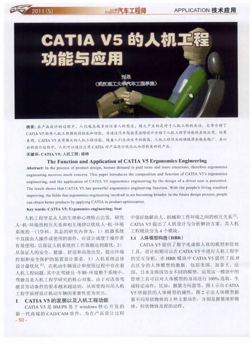
CATIA V5的人机工程功能与应用
2 0 : 5— 6 0 2 1 1.
由于 驾驶 人 员 的 身材 有 差 异 ,可 以再 选 取 9 5百
【】张 立 斌 . 机 工程 学 及其 在汽 车设 计 中 的应 用 []汽 车 运 用, 5 人 J.
20 9 ( ): 00百分 位 的人 体 模 型 ,确 定 出驾 驶 员座 椅 设
( 稿 日期 : 001 —8 收 2 1 .20 )
( 上接 第3页) 8
电动汽 车动 力传 动系 统参数 设 计及合 理 匹配对 其 性能有 很大 的影 响 。根 据 整车动 力 性要求 ,通 过理论
计 算 ,对 电动汽 车 电机 、电池和 传动 系统 进行 匹配计
誓 ¨ 凸 星 j
需将 人体 模型 直接 放入 到所 考 虑 的设备 之 中,减 少 了
制 作 人体 模 型 的过程 ,而 且在 C T A V5中可 以对 人 A I
图 2 人体 模 型 的 修 改
体数据 进 行调 整 ,如 图 1 图 2所 示 ,使得人 体 模型 和
1 人体 测量编辑 ( . 2 HME) 此 模块 可 以通 过人 体测 量 学工 具生 成较 为 高级 的
真 结果 表 明, 电动 汽车 的最 大车 速 、加 速 性和爬 坡性
等 动 力性能 能够满 足 设计 的要求 ,说 明整车 匹配 方案
【 4 】朱正礼,殷承 良,张建武 .基于遗传算法的纯电动汽车动力总成参 数优化 [] J.上海交通大学学报,2 0 ,3 1):10 -9 2 0 4 8(1 9 717 .
参 数满 足 实际要 求 。 由于 驾驶者 身 材各 异 ,所 以在设 计 时必须 对 人机
用 户 自定义人 体模 型 ,从 而使 人体 模 型与 驾驶 员 的模 工程 进行 仔 细研 究 ,确 定其尺 寸 J 于操 作姿 势来 。对 型 吻合 ,得到 更 为精确 的数 据 。在 此模 块 中系 统预 设 说 ,行驶 过程 中驾 驶 员 的脚 始 终放 在踏 板上 , 由于不 了立姿 、 平举 、延伸 平 举 、侧平 举 、坐姿 和跪 姿 6种 同工况 踏板 的角 度 也是有 变化 的,通过试 验 ,由座 椅 、 前 姿势 。可 以根据 实 际要 求先 预 设 1种姿 势 ( 驾驶 员 踏 板和 转 向盘 的位 置 以及驾 驶姿 势参 数 的变化 得 到驾 如 的坐 姿 )然 后在 该姿 势 的基础 上进 行修 改 。
CATIA V5培训教程

工程图设计
05
工程图设计基础
了解工程图的基本概念和术语 学习工程图的投影原理和视图表达方法 掌握工程图中常用的线条、符号和标注方法
工程图视图创建与编辑
1
学习创建基本视图、辅助视图和局部视图的方法
2
掌握视图的编辑和修改技巧,如移动、旋转、缩 放等
了解视图的显示和隐藏控制
了解CATIA V5草图 设计界面及工具栏
掌握草图设计的基本 流程和步骤
学习草图设计的基本 原则和规范
草图绘制工具
学习使用直线、圆弧、圆等基本图形 绘制工具
了解并练习使用样条曲线、螺旋线等 特殊图形绘制工具
掌握使用矩形、多边形等复杂图形绘 制工具
草图编辑与修改
学习使用修剪、延伸、倒角等编辑工具对草图进行修改 掌握使用镜像、阵列等变换工具对草图进行高效编辑
管件和阀门设计
创建各种管件和阀门的3D模型,并将其集成到管路系统中。
管路分析和验证
对管路系统进行流体动力学分析,验证设计的合理性和性能。
模具设计功能
模具分型面设计
利用CATIA V5的模具设计工具,进行模具分型面的设计和优化 ,确保模具的顺利脱模和产品质量的稳定性。
浇注系统设计
设计合理的浇注系统,包括主流道、分流道和浇口等,以确保塑 料在模具内的流动平衡和填充效果。
CATIA V5培训教程
contents
目录
• CATIA V5基础介绍 • 草图设计 • 零件设计 • 装配设计 • 工程图设计 • CATIA V5高级功能介绍
CATIA V5基础介绍
01
CATIA V5概述
CATIA V5是一款高端的三维 CAD/CAM/CAE软件,广泛应 用于航空航天、汽车、机械等领
CATIA V5人机 基础培训3
Module 2
DELMIA V5 Training
D&A Technology (Shanghai) Co., Ltd.
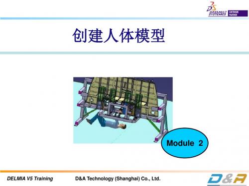
创建人体模型和工作区
概述
人体模型构造器是基于同类中最佳人体模型系统,该系统关联于已存物 理场景进行以人为中心设计论证的调查采集。人体模型构造器定位于在数字 化工作区内创建和操控人体数字模型,以进行人机交互分析。
7. 在当前工作环境里插入一个已存无用的人体模型,并将其定位在: Along X (-10.114in), Along Y (-45.062in), Along Z (0in)。
DELMIA V5 Training
D&A Technology (Shanghai) Co., Ltd.
创建人体模型和工作区
D&A Technology (Shanghai) Co., Ltd.
创建人体模型和工作区
创建工作区——插入人体模型流程
1. 通过主菜单选择“插入 / 新的人体模型”在工作区插入人体模型,弹出的“新人体模型” 对话框如下:。
人体模型选项包含的内容如下: 父层级产品 —— p人体模型在PPR结构树上所依附的产品 人体模型名称 —— 用户预定义标识 性别 —— 人体模型的性别 百分位 —— 标识人体模型所归属的百分位,其值决定着人体 模型的身高和体重。可选值的范围 在0.01到99.9.
DELMIA V5 Training
D&A Technology (Shanghai) Co., Ltd.
练习:搭建工作区
30 min.
内容:搭建工作区和插入人体模型 前提:必须打开DELMIA V5 人体模型构造器平台
详细操作:
CATIA V5简介及基础应用技巧

CATIA V5 简介及基本应用
2、CATIA V5的模块总览
CATIA V5 简介及基本应用
CATIA V5 简介及基本应用
CATIA V5 简介及基本应用
CATIA V5 简介及基本应用
二、CATIA V5软件在使用前的设置
1、常用模块的添加 工具—自定义
CATIA V5 简介及基本应用
这样操作后,所有元素将作为一个整体。
Ps:在三维中写字,需要先在工程图中写好,选择好合适的字体,再另存为dxf文件,然后再打 开dxf文件,乊后的操作步骤不上述相同。
2024CATIAV5介绍与应用

CATIAV5介绍与应用•CATIAV5 Overview•Introduction to Basic Functionsof CATIAV5目录•CATIAV5 Advanced FunctionApplication•Integrating CATIAV5 with othersoftware applications•CATIAV5 operating skills and 目录improvement suggestions01CATIAV5OverviewCATIAV5, developed by Dassault Syst è mes, originating from the need for an advanced 3D CAD tool in the aerospace industry Over time, it evolved to become a comprehensive product development solution With the integration of newtechnologies like parametricdesign, knowledge basedengineering, and advancedsimulation capabilities, CATIAV5has become a leading platformfor product design anddevelopmentToday, CATIAV5 is widely usedacross various industries such asautomotive, aerospace,shipbuilding, and more It hassignificantly transformed the wayproducts are designed,developed, and manufacturedOrigin and Early Development TechnicalAdvancementsGlobal Adoptionand ImpactBackground and Development History of CATIAVAnalysis of Software Characteristics and Advantages•Comprehensive 3D Modeling Capabilities: CATIAV5 offers powerful 3D modeling tools that enable designers to create complex shapes and assemblies with precision•Seamless Integration with Other Software: The software integrations smoothly with other CAD, CAM, and CAE tools, facilitating a seamless workflow between different design and manufacturing processes•Advanced Simulation and Analysis: CATIAV5 provides advanced simulation and analysis capabilities that enable engineers to test and validate designs before manufacturing, saving time and costs •User Friendly Interface: The software boards a user friendly interface that simplifies the learning curve for new users and enhances productivity for experienced designersApplication field and market demand•Automotive Industry: CATIAV5 is widely used in the automotive industry for vehicle design, component design, and assembly validation It advanced surface capabilities make it ideal for styling and Class-A surface development•Aerospace Industry: In the aerospace sector, CATIAV5 is used for aircraft design, engine design, and systems integration It ability to handle large assemblies and complex kinematics make it suitable for aerospace applications•Shipbuilding Industry: The shipbuilding industry utilities CATIAV5 for hull design, outfitting, and piping design The software's ability to handle large data sets and complex geometry facilities effective ship design processes•Other Industries: In addition to automotive, aerospace, and shipbuilding, CATIAV5 finds applications in various other industries such as machinery, consumer goods, and electronics It versatility and02Introduction toBasicFunctions ofCATIAV5Modeling function3D solid modelingCreate complex 3D shapes using a variety of modelingtechniques such as extrusion, rotation, shifting, and moreSurface modelingDesign and modify free form surfaces using advanced surfacemodeling toolsParameter modelingDefine relationships between model features to automaticallyupdate designs when changes are madeSketch based modelingCreate 2D sketches as the basis for 3D models, with tools forconstraint based design and dimensioningComponent assembly: Arrange and combine individual parts into larger assemblies, with tools for positioning, matching, and constraining componentsAssembly analysis: Evaluate the performance of assemblies, including motion simulation and collection detection Bill of Materials (BOM) generation: Automatically create lists of components and assemblies for manufacturing and procurement purposesInteraction checking: Identify and resolve potential claims or overlaps between components in an assemblyAssembly design function2D drawingcreationGenerate professional quality 2D drawings from 3D models, with tools for adding dimensions, annotations, and symbolsDrawingtemplatesCustomize drawinglayouts and formatsusing pre definedtemplates or createyour own templatesfor consistentdrawing standardsDrawingviewsCreate multipleviews of a 3D model,includingorthographic,isometric, andauxiliary viewsDetailedannotationsAdd detailed notesand calls to drawingsto clarify designintent andmanufacturingrequirementsEngineering drawing functionDesign sheet metal components with tools for creating bends, flanges, and other sheet metal featuresSheet metal part modelingSimulate the unfolding and flattering of sheet metal parts to facilitate manufacturing processes such as last cutting orpunching Unfolding and flatteringEvaluate the feasibility and feasibility of sheet metal designs, including checks for potential defects such as teachersor writersSheet metal analysisGenerate detailed drawings and reports for sheet metal components, including bend tables and flat patternsSheet metal documentatio nSheet metal design function03CATIAV5AdvancedFunctionApplicationMastering the creation and editing of basic surfaces such as planes, cylinders, and cones Understanding the principles of surface continuity and quality evaluation Proficient in advanced surface modeling techniques including lofting, sweeping, and filling Demonstrating surface design skills through practical examples such as automotive body designSurface Design Skills and Example DemonstrationsEstablishing a kinematic model of the mechanism tobe analyzed Simulating the motion process and analyzing the resultsMethod and steps of motion simulation analysisDefining constraints and driving forces for eachcomponent Optimizing the design based on simulation results and feedback01Understanding the basic principles and methods of fine element analysis02Mastering the operation and settings of the fine element analysis module in CATIAV503Analyzing product stress, strain, and placement underdifferent load conditions 04Optimizing product designbased on fine elementanalysis resultsApplication of Fine Element Analysis in Product DesignUnderstanding the basic principles and processes of mold designSharing practical experience in mold design, including common problems and solutions Mastering the mold design module in CATIAV5 and its operation methodsDiscussing the trends and developments of mold design technologyMold design process and practical experience sharing04IntegratingCATIAV5 withother softwareapplicationsIntegration method with SolidWorks softwareUsing dedicated interfacesCATIAV5 provides dedicated interfaces to connect with SolidWorks, allowing for seamless dataexchange between the two software packagesImporting and exporting filesBoth CATIAV5 and SolidWorks support variant file formats, such as IGES, STEP, and Parasolid,which can be used to import and export data between the two systemsUsing third party toolsThere are several third party tools available that can facilitate the integration of CATIAV5 andSolidWorks, improving additional functionality and automation01 02 03Preparing data for exportBefore exporting data from CATIAV5 to AutoCAD, it is important to ensure that the data is properly prepared and cleaned up to avoid any issues during the export processUsing DXF/DWG file formatsAutoCAD supports the DXF and DWG file formats, which can be used to exchange 2D data between CATIAV5 and AutoCADManaging layer and block information When exporting data to AutoCAD, it is important to manage layer and block information properly to ensure that the data is organized and easy to work with in AutoCADTips for exchanging data with AutoCAD softwareImplementing Collaborative Work in PLM Systems•Understanding PLM systems: Product Lifecycle Management (PLM) systems are used to manage the entire lifecycle of a product, from concept to disposal CATIAV5 can be integrated with PLM systemsto enable collaborative work across different departments and disciplines•Setting up collaborative workspaces: In a PLM system, collaborative workspaces can be set up to allow multiple users to work on the same project collectively, sharing data and designs in real-time •Managing data and versions: PLM systems provide powerful data and version management capabilities, which can be used to track changes made to designs and ensure that the latest versions are always available to all users•Leveling PLM collaboration tools: PLM systems often come with collaboration tools such as instant messaging, video conferencing, and digital mock up review, which can be used to enhance communication and collaboration between team members working in CATIAV505CATIAV5operating skillsandimprovementsuggestionsSetting shortcut keysCATIAV5 allows users to set shortcut keys for frequently used commands, which can greatly improve work efficiencySaving custom settingsAfter customizing the interface and shortcut keys, users can save their settings as a template for future useCustomizing the toolbarUsers can add or delete toolbars and buttons according to their needs, and adjust the position and size of the toolbarInterface customization and shortcut key setting methodsSummary of common problem solutionsProblem 1Software crashes or freezes Solution: Restart thesoftware or computer, check for software updates, orreduce the complexity of the modelProblem 2Difficultly in importing or exporting data Solution:Check the file format and version compatibility, or usea dedicated data conversion toolProblem 3Slow rendering speed Solution: Optimize the model,reduce the number of surfaces and details, orupgrade the computer hardware01There are many excellent online tutorials available for learning CATIAV5, including video tutorials, text tutorials,and forums Online tutorials02Dassault Syst è mes,the developer of CATIAV5, offers official training courses for users of different levelsOfficial training courses 03Many universities and colleges offer courses on CATIAV5 or related fields, which provide systematic learning opportunities forstudentsAcademicinstitutions04Joining professional associations related to CATIAV5 can help users stayProfessional associationsRecommended learning resources and training opportunitiesTHANKS感谢观看。
- 1、下载文档前请自行甄别文档内容的完整性,平台不提供额外的编辑、内容补充、找答案等附加服务。
- 2、"仅部分预览"的文档,不可在线预览部分如存在完整性等问题,可反馈申请退款(可完整预览的文档不适用该条件!)。
- 3、如文档侵犯您的权益,请联系客服反馈,我们会尽快为您处理(人工客服工作时间:9:00-18:30)。
CATIA V5人机培训与应用1.Human Builder(人体模型建立)人体模型的建立是基于最佳人体模型分类系统的。
人体模型能够非常精确地模拟人体以及人如何与产品互动,这样确保能够像真人一样在工作间自然地操作并完成各种作业。
“人体模型建立”模块侧重于建立一个用于互动分析的数字化人体模型。
此模块包含一些高级工具来创建、操作、分析一个人体模型(基于5th、50th、95th的人体百分比)是如何与产品发生互动的。
人体模型用来评估人与产品关于外形、相配、功能的适应性。
人体模型可以直观地创建和操作并结合DMU来检查诸如伸及范围、视野等特征。
简便易学的互动可以通过一个非人类学家来操作人体上面的各类参数。
工具栏中包括人体模型的生成、性别、百分位、正/反运动学操作、动画生成、单眼/双眼视野仿真以及视野圆锥。
1.1.Human Builder Menu Bar1.1.1.Standard Manikin Creation点击Manikin Creation图标,出现New Manikin对话框:1.1.1.1.Manikin Tab:Father Product:人体模型必须附加在左边树形图的一个Product内,这个Product可以是任何级别的,但不可以是其他任何人体模型。
Manikin name: 在这里为新建的人体模型命名,如:驾驶员、乘客、机械工等。
多个人体模型可以有同一个名字,如果将这栏空白,系统默认命名为Manikin1 (2, 3, etc.),并且保存为Manikin1.CATProduct。
Gender: 在这里选择人体模型的性别。
Percentile: 可以选择从1%至99%的人体百分位。
1.1.1.2.Optional TabPopulation:这里选择人体模型的国籍,系统默认有:美国、加拿大、法国、日本、韩国。
Model: 这里选择希望得到的人体模型的类别,系统提供三种:全身、只有左臂、只有右臂。
Referential:这里选择人体模型上面的参考点,有:眼点、H点(默认)、左脚、右脚、脚底、胯部。
Set Referential to Compass Location:如果这个参数是激活的,就可以使用罗盘指定人体模型的初始位置,如:一个平整的地板。
如果这个参数没有被激活,人体模型就会被放置在系统默认的位置中(坐标原点)。
1.1.2.Changing Manikin Display Attributes点击Display Attributes图标,里面包含:1.1.2.1.Manikin这个栏是空的直到鼠标选择了一个人体模型,选择后,人体模型的名字就会显示在这里。
在这个命令打开后,可以不断地选择其他人体模型,但是选择了新的模型后,前一个就被新的模型替代掉了,并更新相应的名字。
1.1.2.2.显示方式:segments, ellipses, and surfaces。
三种显示方式同时选择至少一种。
1.1.2.3.Center of gravity这里的重心是不可以被做任何操作的。
重心会随着人体各部分的变化而变化,1.1.2.4.Line of sight视线是用来方便处理人体模型的视野的,这条蓝色的线像其他部分一样可以被点选。
例如,它可以在Forward Kinematics 命令中被操作。
1.1.2.5.Resolution辨析率表示每一个绘制表征人体模型的曲面的椭圆上面的点的数量。
系统默认值为32,它的变化范围是4到128。
1.1.3.Inverse Kinematics Behaviors1.1.4.Assigning Descriptions (Memos)点选备忘录图标,选择要写备忘录的人体模型,备忘录窗口就会出现。
写下需要备注的内容后,点击OK。
如果要找回备忘录,重新点击备忘录图标。
备忘录还可以用于视野、人体测量学、人体模型的姿势等。
选择树形图上适当的节点(人体模型、人体测量、视野或身体),相应的备忘录就会显示出来。
ing the Vision Function选择视野图标,或双击树形图上的视野,点击人体模型后就会出现一个新的视野窗口。
在这个窗口中单击右键会出现视野菜单:Export As……输出作为一个图像文件Edit 使用视野对话框编辑视野Close 关闭此窗口视野对话框:1.1.5.1.Type Field就像真人一样,人体模型也可以看到它所在的环境。
它同样可以使用双眼或单只眼睛。
Type选项单允许使用者选择五种视野的表达方式。
当每一种方式选择后,视野窗口会做出相应的变化。
Binocular 双眼视野(左/右单眼视野的交集)Ambinocular 总视野(左/右单眼视野的并集)Right monocular 右眼视野Left monocular 左眼视野Stereo 立体视野(同时显示左/右眼视野)1.1.5.2.Vision TabA.Vision Window:Hide title 隐藏/显示视野窗口上边的台头。
Peripheral contour 此选项显示/隐藏窗口中的视野边界区域。
Central spot视点是视线的末端点,此选项显示/隐藏视点。
Blind spot盲点只表示在单眼的视野中,系统默认盲点为不显示状态。
Rendering...点击此选项,出现系统观察模式菜单,通过菜单可以改变所有窗口的观察模式。
Scale使用比例尺可以对窗口在原始大小至3倍大小之间进行缩放。
B.Display:Line of sight 视线可以被显示/隐藏,视线就像一个末端为控制点的片断,末端的控制点可以依靠IK操作视野。
三种视线:左/右眼视野中的左/右视线,双眼视野/总视野中的中心线。
Blind cone盲锥是用3D图形表示眼睛盲点边界,它只出现在单眼视野中。
系统默认盲锥为不显示状态。
Peripheral cone锥形边界是用3D图形表示视野的边界,系统默认的锥形边界是不显示状态,它依赖于视线是否激活。
Flat display:(平滑)Spherical display:(球面)Boundings display:(跳跃)Bounded cone display:(有界)1.1.5.3.Field of View TabHorizontal monocular:定义单眼模式下水平(XY平面)的视野范围,默认的角度范围是100度。
Horizontal ambinocular:定义总视野模式下水平(XY平面)的视野范围,默认的角度范围是120度。
Vertical top:定义所有视野模式中视点以上的垂直范围,默认的角度范围是35度。
Vertical bottom:定义所有视野模式中视点以下的垂直范围,默认的角度范围是35度。
Central:定义中心视野范围(视网膜中心凹)的范围。
因为这个中心视野是圆形的,所以它的特点是上下左右的范围是相同的一个值。
系统默认的值是6度,最大20度,最小0.5度。
1.1.5.4.Distance TabPonctum proximum:这个参数定义眼睛适应性调节距离范围的最小值,这个值等于距眼睛最近的能够被看清的点与眼睛的距离,默认值为100mm。
Focus distance:焦点距离与激活的视线的长度相等,默认值为300mm。
Ponctum remotum:这个参数定义眼睛适应性调节距离范围的最大值,5m至无穷远,系统定义为无穷远。
ing the Reach Envelope手伸及界面是一个表征人体模型仅仅使用大臂和前臂能够触及到的范围的空间曲面。
整个运动的中心是肩轴点。
可以创建两个伸及界面:左手和右手。
手伸及界面包括在干涉分析中。
点击手伸及界面图标,并且选择人体模型的左手或右手:手伸及界面可以转移到与人体模型绑定的物体上面。
使用Posture Editor(姿态编辑)改变人体模型的姿态,手伸及界面也会发生变化。
如果要删除生成的手伸及界面,右键点击此界面在扩展菜单Left/Right Reach Envelop Object中选择Destroy。
1.1.7.Attaching an Object to a Manikin Segment连接功能可以在人体模型片断与单一或多个物体之间创建一个单向关联。
连接的物体从属于人体模型,一旦被连接,物体随着人体发生位移。
但是要注意的是,这种单向关联意味着只能物体随人体运动。
在进行连接后如果物体发生位移,人体任何部分都不会随物体的位移而变化。
1.1.7.1.Attaching an object to a manikin segmentExample:将人体模型与要连接的物体摆放到合适的位置,点击连接/分离图标,点选要连接的物体,再选择人体模型上面要与物体连接的肢体片断(此例中的右手),此时,连接/分离对话框弹出,点击OK,完成连接。
1.1.7.2.Checking existing attaches on a specific manikin进入人体模型的属性菜单,点击Manikin tab标签,选择Attach tab察看连接管理信息。
下面列出连接的清单。
一个物体同时只可与一个人体模型片断连接,而多个物体可同时与一个人体模型片断连接。
1.1.7.3.Detaching an object from a manikin segment有两种方法断开已经做好的连接:在属性连接管理列表中点选要断开的连接,然后点击列表下面的Detach按键;或使用Attach/Detach命令。
使用Attach/Detach命令:点击命令,然后点选要断开连接的物体,在弹出的对话框中选择Detach Object。
1.2.Manikin Posture Toolbaring the Posture Editor姿态编辑是用来调节人体模型各个部分的正向运动的,人体片断或自由度(DOF)的运动是分步骤进行的,这里可以精确地给出具体的数值。
人体模型由68个铰接点组成,每个点的运动受邻近的点的位置的影响。
点击Posture Editor图标,再选择人体模型,弹出姿态编辑对话框:Segments:列表中为人体模型与人体各个部分一致的名称,点击激活。
Part:这里选择身体各不同的部分,共有3个选项:Hand:编辑手的片断。
Spine:编辑脊柱。
Other:编辑其他所有除了手合脊柱的身体片断。
Side:选择左右,比如左/右臂,左侧为系统默认。
Value使用数值功能可以精确地为人体姿态赋值。
Value percentage slider百分比滑块对应在选定DOF的情况下的运动范围的百分比数值。
Value spinner这里允许使用者输入数值,也可以改变每点一下增长/减少箭头的步进值。
MotionCoupling:运动的范围(弹性、函数极限)关于6个肢体部分是可以被关联的。