Revco 中文操作手册
E+L DC5502莱默尔控制器中文说明书1

E RHARDT + LKRS52-FR5502中文操作說明书目录一、KRS 定型机布边追踪器1.功能……………………………………………………………………2.装设……………………………………………………………………3.安装……………………………………………………………………4.设定编辑………………………………………………………………5.设定DC55.. ……………………………………………………………6.操作和控制盒NT5..……………………………………………………7.最佳的设定……………………………………………………………8.错误讯息………………………………………………………………9.保养维修………………………………………………………………10.技术数据………………………………………………………………3 8 9 11 17 23 24 27 32 32二、红外线布边追踪电眼FR 5502 (数字型)1.总论……………………………………………………………………2.功能……………………………………………………………………3.装设……………………………………………………………………4.安装……………………………………………………………………5.装置设定………………………………………………………………6.操作……………………………………………………………………7.内部设定以及错误讯息………………………………………………8.保养以及维修…………………………………………………………9.配件以及备用零件……………………………………………………10.配线图…………………………………………………………………11.技术数据………………………………………………………………36 36 37 38 39 41 43 46 46 46 46三、KR 52 布边追踪器驱动马达1.安全……………………………………………………………………2.性能设计………………………………………………………………3.功能……………………………………………………………………4.组装……………………………………………………………………5.安装……………………………………………………………………..6.保养维修………………………………………………………………7.损耗品…………………………………………………………………8.配件……………………………………………………………………9.替换注意事项……………………………………………………………10.技术数据…………………………………………………………………48 48 48 50 53 54 54 54 54 60标记说明→:作业要点‖:注意事项! :定型机布边追踪器安全操作事项构造操作说明E + L 定型机布边追踪器操作说明,由总体系统(A)、个别系统(B、C、…W﹚、其他备件表(X)、参数表(Y)、图表(Z)。
varco用户手册(中文版)详解

TDS-11SA顶部驱动钻井系统V ARCO钻井系统用户手册2007年10月系统说明前言手册体例安全知识本手册中凡是出现有可能引起人身伤害或设备损坏的有关信息均以一定格式表示以引起用户注意重要信息、警告或注意小心。
见以下举例并注意这些重要提示。
●表明在操作及维护过程中没有人身伤害及设备损坏的危险。
▲表明有可能损坏设备。
◆表明存在着伤害人身的危险。
在操作、检查及维修前阅读本手册及相关文件以避免人身伤害及设备损坏。
方位说明本手册中涉及的部件前后左右方位假定TDS-11SA对着井口,站在其后面看顶驱系统(TDS-11SA)。
手册式样这一册包括几个独立小本,可以方便地单独运用。
第一章总述说明本册包括组成TDS-11SA顶驱钻井系统的主要部件的说明和操作理论。
TDS-11SA顶部驱动钻井系统具有结构紧凑和轻便的特点。
两套350马力或400马力变频交流钻井电机为TDS-11SA提供钻井动力,一套液压系统为所有辅助功能提供动力,省去了一套单独的液压动力系统和液体伺服回路。
下面的图1-1给出了组成TDS-11SA的九个组成部分。
图1-1 典型的TDS-11SAAC Drilling Motors交流钻井马达Bail提环Carriage and guide beam滑动架及导轨counterbalance system平衡系统Gooseneck鹅颈管bonnet阀罩washpipe packing assembly 冲管盘根总成transmission/motor housing and swivel assembly传动/电机和水龙头总成pipehandler 管子处理装第二章主要部件说明介绍以下介绍的TDS-11SA零部件和定义的条目适用于整个手册。
交流钻井电机TDS-11SA使用了两个400马力或两个350马力的交流电机,垂直并排安装在主机顶部给TDS-11SA提供动力(见图1-2)。
图1-2 交流钻井马达AC 350 hp drilling motor 350马力交流钻井马达350 hp AC drilling motor 350马力交流钻井马达main body主机一个经过改装的“D”型端面将钻井电机联接到主机上。
Revo Calibration 用户手册说明书

Revo Calibration 《用户手册》2022.05 V.1.0目录软件概况 (3)软件介绍 (3)适用产品 (3)软件安装 (4)系统要求 (4)软件下载 (4)用户界面介绍 (5)主页(Home)界面 (5)标定流程界面 (6)精度检测界面 (7)硬件连接 (8)连接步骤 (8)相机标定和精度检测 (9)相机标定 (9)精度测试 (18)其他功能设置 (20)相机设定 (20)帮助中心 (23)联系我们 (23)软件介绍Revo Calibration是我司自主研发的一款针对3D手持便携式扫描仪的标定校准软件。
扫描仪在出厂开箱后及长期使用过程中,用户可以自行使用本软件对扫描仪进行重新校准,以确保扫描时获得高质量、精准的三维模型。
*为什么对相机进行重新标定?扫描仪在出厂前已经过精确标定校准。
但在使用很长时间后,或由于设备受环境变化、外力、碰撞导致相机镜头位置、角度发生轻微形变,以致设备内的原出厂参数不再适用于相机的当前状态。
此时进行扫描及三维重建的结果可能会出现精度偏差,表现为生成的模型(点云)有重叠、构网后模型表面有错层、褶皱等现象。
此时就需要以相机当前的硬件状态为基础,进行重新标定(校准),重置相机内部参数。
适用产品Revo Calibration软件目前仅适用于对POP 2扫描仪(USB有线连接方式)的标定校准,后续将扩展支持更多同系列扫描仪。
系统要求软件下载可在 Revopoint 官网下载软件-Revo Calibration ,下载链接:https:///download/pop-2/下载完成后,直接运行安装包程序,一般按照默认设定执行安装即可。
Windows: Win 8/Win 10 (64位)内存:≥ 8G*不支持Windows 7. Mac with Intel × 86 chip: Mac OS 10.15及其以上版本;Mac with Apple M1 chip: MacOS 11.0 或更高版本;内存≥8G用户界面介绍本章主要介绍Revo Calibration 软件的用户界面。
梅特勒V20水分仪操作说明书

3.2 触摸屏操作
带触摸屏的终端设备仅有控制功能。打开仪器时,触摸屏自动启用。 如果您想在触摸屏上选择一个按键或输入元素,只需要用不锋利的、柔软的物体甚至指尖轻触 即可。 请您注意,切勿使用具有尖角或锋利边角的硬物触及触摸屏表面!否则可能会损伤触摸屏!
在选择这些区后,会打开一个新对话框,里面有一个选 择列表。
在选择这些区后,会打开一个新对话框,里面有其它各 种选择可能性。
在这些区中必须输入一个公式。您可以自由输入,也可 以使用软键建议来调出一个选择列表。
禁用的输入区中的数值只是作为信息显示出来,在所属 的对话框中不能进行编辑。
除了输入区外,还有复选框。您可以激活它们,选择某些功能。复选框能够影响所属对话框的 内容范围,也就是说,根据复选框已经激活或撤销,就会有输入区显示或消失。
V20/V30
5
序言
1 序言
简单精巧!
METTLER TOLEDO 的 Titration Compact 系列装置是先进的紧凑型滴定仪,可以用于各种 不同的领域。例如,它们可以用于质量控制或者研究和开发等,可以满足最高要求。
Titration Compact 系列滴定仪将简单易懂的操作和最高精确性以及出色的可靠性完美地结合 在一起。借助滴定剂自动识别功能 (滴 定管即插即用), 滴定仪自动识别所需滴定剂,而无需 用户干预。即使对于连接打印机或 Stromboli 炉式自动进样器,也完全无需手动调整设置。
整个反应过程持续到全部的水消耗完毕,并在滴定溶液中检测到游离碘。在终点测定时使用双 电压测量指示,即极化双铂 (针) 电极上的电位降低到一个特定值以下 (例 如 100mV)。
2.1 容量法水份测定
REVO 手持单元操作手册说明书
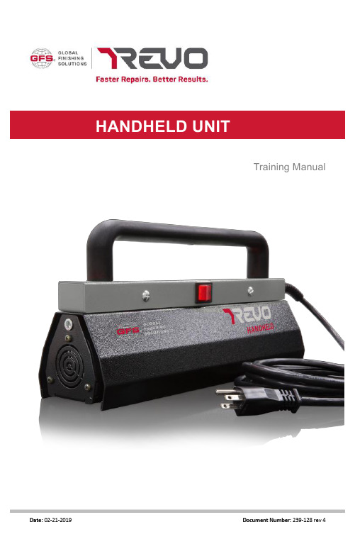
CONTENTSHow it Works. . . . . . . . . . . . . . . . . . . . . . . . . . . . . . . . . . . . . . . . . . . . . . . . . . . . . .3 Handheld Unit Diagram & Specifications. . . . . . . . . . . . . . . . . . . . . . . . . . . . . .. 4-5 Powering On . . . . . . . . . . . . . . . . . . . . . . . . . . . . . . . . . . . . . . . . . . . . . . . . . . . . . .6 Overview . . . . . . . . . . . . . . . . . . . . . . . . . . . . . . . . . . . . . . . . . . . . . . . . . . . . . . . . .7 Using REVO Handheld Unit:Body Filler . . . . . . . . . . . . . . . . . . . . . . . . . . . . . . . . . . . . . . . . . . . . . . . . . . . .8 Primer Surfacer. . . . . . . . . . . . . . . . . . . . . . . . . . . . . . . . . . . . . . . . . . . . . . . .9 Basecoat . . . . . . . . . . . . . . . . . . . . . . . . . . . . . . . . . . . . . . . . . . . . . . . . . . . . .10 Clearcoat . . . . . . . . . . . . . . . . . . . . . . . . . . . . . . . . . . . . . . . . . . . . . . . . . . . .11 Single Stage Paint . . . . . . . . . . . . . . . . . . . . . . . . . . . . . . . . . . . . . . . . . . . . .12 Plastic Repair . . . . . . . . . . . . . . . . . . . . . . . . . . . . . . . . . . . . . . . . . . . . . . . . 13 Other Uses . . . . . . . . . . . . . . . . . . . . . . . . . . . . . . . . . . . . . . . . . . . . . . . . . . .14 Maintenance . . . . . . . . . . . . . . . . . . . . . . . . . . . . . . . . . . . . . . . . . . . . . . . . . . . . .15 Parts Breakout . . . . . . . . . . . . . . . . . . . . . . . . . . . . . . . . . . . . . . . . . . . . . . . . . . . 16HOW IT WORKSREVO Systems use short wave infrared light to cure coatings from the inside out. Traditional methods of curing use medium or long wave infrared. Medium and long wave infrared light cures from the outside in —which can trap solvents or only cure the surface —leaving coatings wet on the inside. Short wave differs from these other methods by penetrating the applied coating and heating the substrate beneath, forcing all of the solvents out and resulting in a uniform and complete cure. Since it works from the inside out, REVO can cure up to three full coats of a product in one curing cycle with no need to cure between coats. Additionally, the infrared technology works on nearly all substrates including steel, aluminum, fiberglass, plastic, carbon fiber, etc.HANDHELD UNIT DIAGRAMHeat ShieldMain Power Switch Parameters DecalInfrared BulbHandle10 Amp at 110 VoltHANDHELD UNITSPECIFICATIONSPlug the unit into a 110V outlet rated for at least 10 amps.Flip the power switch to the on position. The indicator light willIf any of these things aren’t working, contact GFS or your local distributor for support.Using the REVO Handheld Unit for Body Filler:1.Mix and apply the body filler.•Be sure to mix your body filler properly! Many people put too much hardener in the filler. Follow the directions on the can. Too much hardener can cause pinholes or bubbling.•Automix filler systems are recommended to ensure mixing accuracy.•Always use two part fillers and putties. One part glazing putties and fillers are not compatible with REVO.2.Turn on the Handheld and wave the unit back and forth over the repair area at a distance of 2 inches from the surface until target temperature is achieved (140⁰ F).3.Move unit 2-3 feet away from the surface and continueto wave back and forth to maintain the target temperature for the recommended amount of time.4.The temperature should be constantly monitored with an infrared thermometer.5.The target time and temperatures are listed on the decal on the machine (picture 2).6.When the panel has returned to ambient temperature you can begin sanding the body filler.•Cooling can be accelerated by using a blow gun to force air over the panel.BODY FILLERUsing the REVO Handheld Unit for Primer Surfacer:1.Mix and apply the Primer Surfacer.•Always use slow or medium hardener and reducers. Do not use fast products.•Mix primer on the scale to ensure proper mixing.•You can use the REVO between coats to speed up flash time.2.Turn on the Handheld and wave the unit back and forth over the repair area at a distance of 2 inches from the surface until target temperature is achieved (185⁰ F).3.Move unit 2-3 feet away from the surface and continue to wave back and forth to maintain target temperature for the recommended amount of time.4.The temperature should be constantly monitored with an infrared thermometer.5.The target time and temperatures are listed on the decal on the machine (picture 2).6.When the panel has returned to ambient temperature you can begin sanding the primer.•Cooling can be accelerated by using a blow gun to force air over the panel.6.If re-priming is needed after sanding, primer can be reapplied immediately and the same curing procedure should be followed.PRIMER SURFACERUsing the REVO Handheld Unit for Basecoat:1.Apply all coats of basecoat per manufacturer’s recommendations.•Drying with REVO between coats is not required, but can be done to speed up flash times.•For tri-coats: Dry with REVO after last coat of basecoat, and again after last coat of midcoat.2.Turn on the Handheld and wave the unit back and forth over the repair area at a distance of 2 inches from the surface until target temperature is achieved (140⁰ F).3.Move unit 2-3 feet away from the surface and continueto wave back and forth to maintain target temperature for the recommended amount of time.4.The temperature should be constantly monitoredwith an infrared thermometer.5.The target time and temperatures are listed on the decal on the machine (picture 2).6.When the panel has returned to ambient temperature you can begin applying clearcoat.•Cooling can be accelerated by using a blow gun to force air over the panel.•If nibbing or any additional coats of base are needed, reapply basecoat and follow the same drying procedure.BASECOATCLEARCOATUsing the REVO Handheld Unit for Clearcoat:1.Mix and apply all coats of clearcoat per manufacturers recommendations.•There is no need to cure with REVO between coats.•Only use slow or medium hardeners and reducers!•Be sure to use a “Baking Clearcoat.” Air dry clears are not designed to handle heat and curing them with REVO could result in solvent popping or bubbling.2.Turn on the Handheld and wave the unit back and forth over the repair area at a distance of2 inches from the surface until target temperature is achieved (200⁰ F).3.Move unit 2-3 feet away from the surface and continue towave back and forth to maintain target temperature for therecommended amount of time.4.The temperature should be constantly monitored withan infrared thermometer.5.The target time and temperatures are listed on the decalon the machine (picture 2).6.When the panel has returned to ambient temperature youcan begin assembling parts or start the buffing process.Cooling should not be accelerated, let it cool naturally.Using the REVO Handheld Unit for Single Stage Paint:1.Mix and apply all coats of the single stage paint per manufacturers recommendations.•There is no need to cure with REVO between coats.•Only use slow or medium hardeners and reducers!2.Turn on the Handheld and wave the unit back and forth over the repair area at a distance of 2 inches from the surface until target temperature is achieved (185-200⁰ F).3.Move unit 2-3 feet away from the surface and continueto wave back and forth to maintain target temperature for the recommended amount of time.4.The temperature should be constantly monitored withan infrared thermometer.5.Treat single stage paint like clearcoat. The target timeand temperatures are listed on the decal on the machine (picture 2).6.When the panel has returned to ambient temperatureyou can begin assembling parts or start the buffing process. Cooling should not be accelerated, let it cool naturally.SINGLE STAGE PAINTUsing the REVO Handheld Unit for Plastic Repair:1.Turn on the Handheld and wave the unit back and forth over the repair area at a distance of2 inches from the surface until target temperature is achieved (200-225 degrees Fahrenheit).Plastic parts become very malleable at this temperature.2.Push out any major dents and continue to warm theplastic to relive any stressed areas.3.The temperature should be constantly monitoredwith an infrared thermometer.4.Overheating of the plastic can warp, damage or meltit beyond repair.5.Follow all the curing and cooling procedures listed forthe other products used to finish the plastic repair.PLASTIC REPAIROTHER USESUsing the REVO Handheld Unit for Other uses:1.There are several other uses for the Handheld unit. (Contact GFS for product specific recommendations)• A second type of clearcoat or primer•Plastic repair material•Seam sealers•Rock or chip guard•Decal removal•Emblem removal•Soft set glass removal•PPF removal•Panel bond adhesive2. A safe temperature to be used over any already cured paint is around 200 degrees Fahrenheit.This is a good starting point for any of the procedures listed on this page. Temperature can be gradually increased from there if needed.HANDHELDPosition Code Description18109266SWITCH ON/OFF28172363CABLE CLAMP38172108CABLE SJT 3CAWG16。
RevcoTM RDE 系列、 FormaTM FDE 系列、 HERAfreezeTM HDE 系

超低温降温仪 Revco TM RDE 系列、Forma TM FDE 系列、HERAfreeze TM HDE 系列和 Thermo Scientific TM TDE 系列安装和操作329712H61 •修订版 F • 2022 年 3 月重要请阅读本说明手册。
不按照本手册中的说明操作可能会导致设备损坏、操作人员受伤和设备性能低下。
小心所有内部调整和维护均必须由合格的检修人员执行。
本手册中的材料仅供参考。
其中的内容和产品可能发生更改,恕不另行通知。
赛默飞世尔科技不提供任何关于本手册的声明或担保。
在任何情况下,Thermo 对因使用本手册或与使用本手册相关的直接或间接损坏不负任何责任。
© 2022 Thermo Fisher Scientific Inc. 保留所有权利。
目录型号 (1)安全注意事项 (2)开箱 (3)装箱单 (3)一般性建议 (4)温度监测 (4)一般用法 (4)初次装载 (4)电池舱门打开/关闭 (4)运行标准 (5)电气规格 (5)安装 (6)位置 (6)保护导体电流 (6)调平 (6)刮冰刀 (6)备份系统(可选) (7)超级绝缘机柜结构 (7)门操作 (7)压力均衡口 (7)安装远程警报连接器 (7)预期用途 (8)操作 (9)初始启动 (9)操作概述 (9)显示 (9)设置 (10)关机 (10)刮冰刀说明 (11)预期用途 (11)非预期用途 (11)注意事项和使用方法 (11)备份系统(可选) (12)CO2和 LN2注意事项 (12)安装 (12)启动 (13)操作 (13)温度记录仪(可选) (14)设置和操作 (14)更换记录纸 (14)校准调整 (14)维护 (15)清洁冷凝器 (15)清洁冷凝器过滤器 (15)垫圈维护 (15)为降温仪除霜 (15)电池维护 (15)维护计划 (16)故障排除指南 (17)错误代码 (20)保修 (21)保修(国际) (22)附录 A:警报摘要 (23)附录 B:Modbus ASCII 参数表 (25)WEEE 合规 (34)联系信息 (35)型号表 1. 适用的型号Forma - FDExxx86F*300/400/500/600A/D/VForma - FDExxx86F* - ULTS 300/400/500/600A/D/VThermo Scientific –TDExxx86F*300/400/500/600A/D/VThermo Scientific –TDExxx86F*- ULTS300/400/500/600A/D/VHERAfreeze – HDExxx86F*300/400/500/600A/D/VRevco - RDExxx86F*300/400/500/600A/D/V1|型号Thermo Fisher Scientific 超低温降温仪安全注意事项在本手册中,使用下列符号和惯例:下面列举了一些适用于本产品的重要安全防范措施:EMC(适用时)此设备的 EMC 注册仅限商业用途。
快捷(CREATOR)CROSS矩阵手册

本手册为 CREATOR Electronics 版权所有,未经许可,任何单位或个人不得将本手册之部分或其全 部内容作为商业用途。
本手册版权受《中华人民共和国著作权法》及其他知识产权法规保护。未经书面许可不得复印或散 布。
creatorcross系列混合矩阵切换器用户手册v13版广州市天誉创高电子科技有限公司corporationchina符号的意义安全指示使用说明书和设备上都使用了符号指出可能对用户或他人造成的伤害以及财产受损的风险以便您能够安全正确地使用设备
CREATOR CORPORATION(CHINA)
CROSS 系列混合矩阵切换器 用户置不成功的内容及一些 需要注意的相关信息。
重要说明
警告
为确保设备可靠使用及人员的安全,请在安 装、使用和维护时,请遵守以下事项: 安装时的注意事项 ◆ 请勿在下列场所使用本产品:有灰尘、油烟、 导电性尘埃、腐蚀性气体、可燃性气体的场所;暴 露于高温、结露、风雨的场合;有振动、冲击的场 合。电击、火灾、误操作也会导致产品损坏和恶化;
◆ 在进行螺丝孔加工和接线时,不要使金属屑和 电线头掉入控制器的通风孔内,这有可能引起火 灾、故障、误操作;
运行和保养时的注意事项 ◆ 请勿在通电时触摸端子,否则可能引起电击、 误操作;
◆ 请在关闭电源后进行清扫和端子的旋紧工作, 通电时这些操作可能引起触电;
◆ 请在关闭电源后进行通讯信号电缆的连接或 拆除、扩展板卡或控制单元的电缆连接或拆除等操 作,否则可能引起设备损坏、误操作;
产品报废时的注意事项 ◆ 电解电容的爆炸:电路板上的电解电容器焚烧 时可能发生爆炸;
瑞乐科模30C2 31C2三路液位传感器操作手册说明书

3-WAYFLEX LEVELLIQUID LEVEL SWITCH OPERATION MANUALOMP# LS-3 – 5/19 1.0INTRODUCTIONThe Ruelco Model 30C2 (2” NPT Mount)/31C2 (Flange Mount) 3-way pneumatic liquid level switch is typically mounted directly into a tank or vessel or in an optional external cage (See Figures 1,2). Horizontal or hang down displacer elements are available. This displacer operates a pneumatic valve when a liquid in a tank or a pressurized vessel reaches a predetermined level. The operation mode, as a high or a low level sensor, is selected by rotating the valve body 180 degrees.FIG. 1TYPICAL MOUNTING OF MODEL 30C2LEVEL SWITCHESFIG. 2MODEL 30C2 SHOWN INMODEL 3C01 EXTERNAL CAGE 2.0OPERATION (See Fig. 3)When in the non-tripped condition, the3-way pneumatic valve is configured asa normally open valve when set for highlevel detection and as a normally closedvalve when set for low level detection.When used as a high level sensor, thevalve will allow air flow from inlet tooutlet when the liquid is below thedisplacer. When liquid contacts thedisplacer, the valve will block the inletpressure and vent the outlet pressure.When used as a low level sensor, thevalve will allow air flow from inlet tooutlet when the liquid is above thedisplacer. When liquid no longercontacts the displacer, the valve willblock the inlet pressure and vent theoutlet pressure.Because of the balanced design of thevalve, variations in instrument pressurefrom 5 to 50 PSI will have little effecton level switch performance.The switch senses a change in thebuoyancy of a displacer assembly insidea pressurized or unpressurized vessel.To transmit the buoyancy change, apivoting action is used. The I.D. of thecone contacts the pivot attached to thepush rod and valve body. The o-ring(provides a pressure tight seal betweenthe body and the shaft of the coneprotruding through the o-ring. Pressurein the vessel, if any, acting on the shaftof the cone, forces the cone against thepivot point on the valve body. Theposition of this point, at the center of theo-ring, allows the displacer assembly tomove up or down.2.1HIGH LEVEL OPERATION(NORMALLY OPEN)As the liquid level rises and begins tocover the displacer assembly, thebuoyancy in the liquid reduces thecounterclockwise rotational force on thecone. At some point, the spring willexert a greater clockwise rotational forceand cause the cone to push the valvestem downward, and act on the push rodand 3-way valve. This allows thepressure present at the outlet to ventthrough the weep holes in the valvebody while blocking the inlet pressure.2.2LOW LEVEL OPERATION(NORMALLY CLOSED)As the liquid level falls and begins touncover the displacer assembly, itsbuoyancy in the liquid increases thecounterclockwise rotational force on thecone. At some point, the displacer willexert a greater clockwise rotational forceand cause the cone to push the valvestem upward, and act on the push rodand 3-way valve. This allows thepressure present at the outlet to ventthrough the weep holes in the valvebody while blocking the inlet pressure.NOTE: THE VALVE CAN BE USEDWITH OPPOSITE FUNCTION IFROTATED 180 DEG.3.0INSTALLATION3.1 EXTERNAL CAGE TO VESSELIt is suggested that the level switch beinstalled in an external cage formaintenance and testing purposes. Onerecommended piping system formounting an external cage to a vessel isshown in Figure 1. The valves aboveand below the cage are required fortesting and maintenance purposes.If a cage with butt weld connections isused, the level switch should beremoved from the cage before welding.This will prevent weld sparks fromdamaging the displacer assembly.Remove the switch from the cage as perinstructions in Paragraphs 5.2.1through 5.2.2 of the FULLDISASSEMBLY section of this manual.After welding, install the level switch asper instructions in Section 3.2,INSTALLING LEVEL SWITCH INCAGE.If the cage has threaded or flangedprocess connections, the level switchdoes not have to be removed beforemounting the switch to the vessel. Cageswith 1” NPT process connections maybe installed on the vessel with 1”, ¾”or ½” O.D. piping.CAUTION: Be sure the pressurerating of all valves, pipe and pipefittings meets or exceeds the workingpressure of the vessel on which theyare to be installed. Adequate supportfor long pipe runs should be providedto prevent excessive vibrations of thelevel switch.It is recommended that external cages beinstalled with the process connections asclose to vertical and the cage length asclose to horizontal as possible. This willinsure the proper liquid flow into andout of the cage.3.2LEVEL SWITCH INSTALLATIONBefore installing a level switch into anexternal cage or mating flange, verifythat level switch is set up or theoperation required (i.e., high or lowliquid level detection). See Section 4.0,CHANGING MODE OF OPERATIONand Figure 5. NOTE: When directmounting a level switch to a tank orvessel, verify that the end displacerassembly will be at least ½” (13mm)longer than the 2” connection on whichit is being installed. (See Figure 4).TOOLS REQUIRED:A 2.125” openend wrench or a suitable adjustablewrench or pipe wrench.3.2.1Clean any dirt or debris from the 2”NPT pipe threads and the external cage(if any are being utilized).3.2.2Apply Teflon tape or other threadsealing compound to the 2” NPT threadson the level switch. 3.2.3Apply an anti-galling compound to the2” NPT female thread into which theswitch is installed.3.2.4 Screw the level switch into themounting thread and tighten with thewrench. When tight the spring cap mustbe up as shown in Fig. 5.FIG. 3CAUTION: If using a pipe wrench, do not allow the wrench jaws to contact the spring cap. Wrench forces may damage the cap and prevent the switch from operating properly.NOTE: THE SPRING CAP MUST ALWAYS BE IN THE VERTICAL POSITION AS SHOWN IN FIG. 5 FOR THE “FLEX LEVEL” SWITCH TO OPERATE PROPERLY.FIG. 4TYPICAL DIRECT MOUNTING4.0CHANGING MODE OFOPERATIONTOOLS REQUIRED: 3/16” Allen Wrench The level switch can be changed from high level detection to low level detection very easily. If the level switch is installed into a pressurized cage or vessel, the pressure does not have to be removed, but the caution in Section 4.2 should be followed closely. Fig. 5 shows the proper orientation of the level switch function markings for high and low level operation.FIG. 54.1UNPRESSURIZED CAGEOR VESSEL4.1.1 Verify that no pressure ispresent in the cage or vessel. Ifthis cannot be verified, followinstructions in Section 4.2PRESSURIZED CAGE ORVESSEL.4.1.2Block and bleed the instrumentpressure from the inlet. Removeany instrument tubing connectedto the inlet.4.1.3With the 3/16” Allen wrench,remove the four hex socket headcap screws. Rotate the valvebody 180 degrees to change themode of operation from high tolow or from low to high asdesired. See Fig. 5 for propervalve body orientation.4.1.4Replace the four hex socket capscrews and tighten.4.1.5Connect the instrument supplyif it was disconnected.4.2PRESSURIZED CAGE OR VESSEL 4.2.1Block and bleed the instrumentpressure from inlet. Remove anyinstrument tubing connected tothe inlet.4.2.2Use a 3/16” Allen wrench andremove two of the hex sockethead cap screws that arediagonally apart. Replace thetwo hex socket head cap screwsjust removed with two ¼”-20screws or bolts that are 1-1/4’ to1-1/2” long. These serve as asafety stop in the event the levelswitch has received unknowndamage. Rotate the remainingtwo screws one turn at a time,alternating between the two.The process pressure acting onthe end of the cone that isprotruding through the bodywill move the valve bodyoutward as the two screws areturned. When the valve bodyhas stopped moving, remove thefour screws completely. Rotatethe valve body 180 degrees tochange the mode of operationfrom high to low or from low tohigh as desired. See Fig. 5 forproper valve body orientation. CAUTION: THE VALVE BODY SHOULD MOVE OUTWARD 1/16” AND STOP AS THE DISPLACER ASSEMBLY CONTACTS THE BODY. IF THE PROCESS PRESSURE IS STILL EXERTING A FORCE ON THE VALVE BODY AFTER 1-1/2 TURNS, THEN STOP TURNING THE TWO SCREWS. THE UNIT MAY HAVE DAMAGE THAT WILL ALLOW THE CONE TO DISENGAGE THE O-RING AND THE PROCESS PRESSURE AND MEDIUM WILL ESCAPE THROUGH THE BODY. THE PROCESS PRESSURE WILL HAVE TO BE REMOVED FROM THE CAGE OR VESSEL BEFORE ANY FURTHER DISASSEMBLY IS POSSIBLE.4.2.3 Replace the four hex socket head capscrews and tighten.4.2.4 Connect the instrument supply if it wasdisconnected.5.0 DISASSEMBLY (SEE FIG. 1 and 3) TOOLS REQUIRED:7/16” open end wrench or adjustable wrench5/8” open end wrench or adjustable wrench3/16” Allen wrench1/8” Allen wrenchNeedle nose pliersPliersO-ring pick or small screwdriverLarge adjustable wrench or pipe wrench 5.1PARTIAL DISASSEMBLY(3-WAY POPPET VALVE REPAIR) CAUTION: ONLY THE VALVE BODY CAN BE REMOVED FROM THE LEVEL SWITCH UNIT WITHOUT DEPRESSURIZING THE CAGE OR VESSEL. ANY FURTHER DISASSEMBLY WITH PRESSURE PRESENT ON THE CAGE OR VESSEL WILL RESULT IN SEVERE PERSONAL INJURY OR DAMAGE TO EQUIPMENT.5.1.1It is not necessary to completelydisassembly the unit to remove the valvebody from the level switch. It is notrequired to depressurize the cage or thevessel the level switch is installed in, butit is recommended to do so if possible.5.1.2To remove the valve body when thelevel switch is installed in a pressurizedcage or vessel, follow instructions inParagraph 5.1.3. If the cage or vessel isnot pressurized, use a 3/16” Allenwrench and remove the four hex sockethead cap screws.5.1.3Use a 1/8” Allen wrench and loosen thethree hex socket head set screws that areon the outside of the 3-way valve. Thiswill allow for the removal of the 3-wayvalve from the level switch.5.1.4Note the orientation of the Push Rod andensure this is not lost.CAUTION: THE VALVE BODY SHOULD MOVE OUTWARD 1/16” AND STOP AS THE DISPLACER ASSEMBLY CONTACTS THE BODY. IF THE PROCESS PRESSURE IS STILL EXERTING A FORCE ON THE VALVE BODY AFTER 1-1/2 TURNS, THEN STOP TURNING THE TWO SCREWS. THE UNIT MAY HAVE DAMAGE THAT WILL ALLOW THE CONE TO DISENGAGE THE O-RING (4) AND THE PROCESS PRESSURE AND MEDIUM WILL ESCAPE THROUGH THE BODY. THE PROCESSPRESSURE WILL HAVE TO BE REMOVED FROM THE CAGE OR VESSEL BEFORE ANY FURTHER DISASSEMBLY IS POSSIBLE.5.1.5Loosen the retainer and the stinger canbe accessed.5.1.6The seals may be replaced as perinstructions in the Section 6.0 REPAIRand ASSEMBLY.5.2FULL DISASSEMBLY CAUTION: ALL PRESSURE MUST BE REMOVED FROM THE CAGE OR VESSEL BEFORE FULL DISASSEMBLY CAN BE PERFORMED. FAILURE TO REMOVE THE PRESSURE MAY RESULT IN PERSONAL INJURY OR DAMAGE TO EQUIPMENT.5.2.1Verify that all pressure has beenremoved from the cage or vessel anddrain the liquid to a level below thelevel switch.5.2.2Using the large adjustable wrench orpipe wrench, remove the level switchfrom the cage or vessel.5.2.3Hold the float rod (2) with the pliers androtate it counterclockwise to remove itfrom the level switch.5.2.4Normally it is not necessary to removethe displacer or float assembly from thefloat rod. If required, loosen the lock nut(18) and unthread the displacer or floatassembly from the float rod.5.2.5Follow instructions in Section 5.1PARTIAL DISASSEMBLY to removeand disassembly the valve body.5.2.6Use the 5/8” wrench and rotate thespring cap counterclockwise to removeit from the body. Care should be takennot to lose the spring and spring guide. 5.2.7Using pliers to grip the O.D. of thepivot, rotate it counterclockwise tounthread it from the valve body.5.2.8Push the threaded end of the conethrough the body.5.2.9Using an o-ring pick or smallscrewdriver, remove the o-ring from thebody.6.0 REPAIR AND ASSEMBLY:REFER TO DATA SHEET FORREPLACEMENT PART NUMBERS TOOLS REQUIRED:7/16” open end wrench or adjustable wrench5/8” open end wrench or adjustable wrench3/16” Allen wrenchNeedle nose pliersSafety solventSilicone based o-ring lubricantLarge adjustable wrench or pipe wrench6.1 Using appropriate safety solvent, cleanall parts.6.2Inspect the I.D. of the valve retainer andthe O.D. of the valve stem for nicks andgouges. Replace any worn or damagedparts.6.3The point of the pivot should not beflattened or bent. The sealing surfaces(side and bottom) for the seat o-ringshould be free of pits and gouges.Replace if necessary.6.4If the level switch has a stainless steeldisplacer assembly, it should be free ofdents, cracks or holes.6.5Lubricate all seals from the repair kitwith a silicone-based lubricant.6.6Install the valve seat o-ring into thevalve body and push it completely to thebottom of the receptacle.6.7Install the valve stem o-ring and thevalve retainer o-ring. Lubricate thevalve stem o-ring and insert the valvestem into the valve retainer.6.8Using the needle nose pliers, install thevalve retainer with valve stem installedinto the valve body and tighten.6.9Thread the pivot onto the valve bodyand firmly tighten with pliers.6.10Install the body o-ring into the body. 6.11Lubricate the shaft and the threads onthe threaded end of the cone. Install thecone into the body by turning clockwiseand pushing gently.6.12Align the body tabs with the slots in thecone and slide the valve body into thelevel switch body.6.13Arrange the valve body in the correctposition for the desired high or lowoperation. See Fig. 5. Install and tightenthe four hex socket head cap screws. 6.14Thread the float rod onto the cone andtighten securely with pliers. If thedisplacer assembly was removed,reinstall and tighten the lock nutsecurely.6.15Insert the spring and spring guide intothe spring cap. Install the spring cap intothe body and tighten.6.16Replace the level switch assembly intothe cage or mating flange as perinstructions in Section 3INSTALLATION.7.0RECOMMENDED MAINTENANCE PROCEDURE INTERVAL Test switch in place with every 30 days Process liquids to checkFor proper operation.Clean vent ports of debris every 30 days Replace body seal (4) as required.TROUBLESHOOTINGPROBLEM PROBABLE CAUSE RECOMMENDED ACTION 1) Level switch does notfunctionA) Debris blocking the vent port Clean vent port and test switchB) Trash on inside of the cone(21). Remove the valve body (9) per procedures in Section 5.1 and clean cone I.D.C) Poppet valve (18) sticking Follow procedures in Sections5.1 and6.0 to disassemble andreplace the seals (19)D) Inlet port plugged. Disconnect all instrument tubingand clean inlet port. Cleaninstrumentation system filters.E) Connecting tubing plugged. Remove and clean or replaceinstrument tubing. Cleaninstrumentation system filters.F) Trash accumulation on displacer assembly (1). Remove switch from vessel or cage per procedures in Section 5.2G) “FLEX-LEVEL” not installed properly. Use instructions given in Section 3.0 to properly install the switch.2) Liquid or gas leakage from vent port. A) Poppet valve seals (19)damaged or worn.Follow procedures in Section 5.1and 6.0 to disassemble andreplace the seals (19).B) Body seal (4) damaged orwornReplace body seal (4) perinstructions in Section 5.0 and6.0.CONSULT THE FACTORY OR AN AUTHORIZED DEALER IF THE SWITCH CANNOT BE REPAIRED BY FOLLOWING THESE PROCEDURES.。
- 1、下载文档前请自行甄别文档内容的完整性,平台不提供额外的编辑、内容补充、找答案等附加服务。
- 2、"仅部分预览"的文档,不可在线预览部分如存在完整性等问题,可反馈申请退款(可完整预览的文档不适用该条件!)。
- 3、如文档侵犯您的权益,请联系客服反馈,我们会尽快为您处理(人工客服工作时间:9:00-18:30)。
北京总部 电 话:010-8238 8866
广州分公司 电 话:020-3837 3203 传 真:020-3837 1123
上海分公司 电 话:021-6226 3969 传 真:021-6226 3225
成都分公司 电 话:028-8509 7222 传 真:028-8509 1399
传 真:010-8238 8989
传 真:010-8238 8989
中国科学院
东方科学仪器进出口集团公司
北京五洲东方科技发展有限公司
Beijing Oriental Sc ience & Technology Deve lopment Ltd.
一、 Thermo Scientific Revco -86℃超低温冰箱
Revco 超低温冰箱具有稳定的制冷性能,其制冷系统包括: 1. Copland 公司专门为 Revco 设计制造的高性能 2x1HP 压缩机;独特合成设计的 POE 润滑油, 磨损大大减小;轴承增大,增加了机械性能和负载能力,尤其适合重负荷条件下运行。 2. 3. 4. 使用杜邦(Dupont)Sura 环保冷媒,吸放热能力强,大大提高制冷能力 复叠式制冷设计 所有型号均具有压力平衡口,方便冰箱开门
北京总部 电 话:010-8238 8866
广州分公司 电 话:020-3837 3203 传 真:020-3837 1123
上海分公司 电 话:021-6226 3969 传 真:021-6226 3225
成都分公司 电 话:028-8509 7222 传 真:028-8509 1399
传 真:010-8238 8989
CAUTION! 请不要丢弃卧式超低温冰箱的内盖,它对卧式冰箱的精确控温、控湿以及冰箱的高效使用起很大
北京总部 电 话:010-8238 8866
广州分公司 电 话:020-3837 3203 传 真:020-3837 1123
上海分公司 电 话:021-6226 3969 传 真:021-6226 3225
成都分公司 电 话:028-8509 7222 传 真:028-8509 1399
传 真:010-8238 8989
中国科学院
东方科学仪器进出口集团公司
北京五洲东方科技发展有限公司
Beijing Oriental Sc ience & Technology Deve lopment Ltd. (3) 报警状态显示键:将开机钥匙拧至“alarm on”的位置,此灯亮,表示仪器报警状态已经激活。 (4) 电源故障显示器:此灯亮表示电源系统故障。 (5) 温度调节按钮:按住此按钮,调节冰箱的温度。 (6) 温度指示器:此灯亮表示箱体出于使用状态。 (7) 温度显示器窗口:显示箱体内的温度,报警等信息。 (8) 温度调节键: 降温键, 升温键
中国科学院
东方科学仪器进出口集团公司
北京五洲东方科技发展有限公司
Beijing Oriental Sc ience & Technology Deve lopment Ltd. Value plus 系列:立式冰箱的压力平衡孔位于冰箱外门和眼睛基本平齐的部位。 两种系列的平衡孔均具有加热和自动熔霜的功能,但是过多的冰霜仍然会导致平衡孔的堵塞, 因此周期性清理平衡孔是必要的,可使用尼龙的刷子小心清理。
初次装载样品,如果没有按照此程序进行或者过量装载,将会损害压缩机进而影响样品 的安全性。 2. 打开包装 请在见到货物时先仔细检查包装的外观是否有明显的破损,如发现破损请马上联系货运人员。若 没有破损,请打开包装箱,仔细检查仪器本身有无明显或不明显损坏,如发现损坏请马上联系货 运人员,并要求其检查运输设备和运输工具。在没有得到 Revco 的授权前请不要将仪器寄回 Revco 公司。
二、 安全警示
1. 警示标志 在操作手册和产品的机身上都会贴有各种“WARNING”“CAUTION”的警示标志。 “WARNING”警告:潜在危险部位或情况,如果未能避免,可能会对产品造成损害或者形成人员危 险。 “CAUTION”小心:潜在危险部位或情况,如果未能避免,可能会对仪器或产品造成轻度损害。 在安调、使用和维护本仪器时,请仔细阅读操作手册和仪器上的警告,以避免发生事故或对产品 和人员造成损害和危险。 本产品的使用范围在操作手册以及相关的资料中都已经详细说明,使用前请仔细阅读,并检查您 的使用意图是否与其相符合。 2. 为确保安全正确的使用本仪器,请遵循下面的提示: (1) 请不要改装本仪器,尤其是控制器。使用 OEM 生产的配件请确保配件的精确性和质量。 (2) 本仪器的使用应当是与本地的电力系统相匹配的,请不要电力过载使用。 (3) 在对本仪器进行维护、清洗、故障排除时请确保仪器已经完全断电。
成都分公司 电 话:028-8509 7222 传 真:028-8509 1399
传 真:010-8238 8989
中国科学院
东方科学仪器进出口集团公司
北京五洲东方科技发展有限公司
Beijing Oriental Sc ience & Technology Deve lopment Ltd. 作用。立式冰箱没有内盖,但是具有内门。 3. 安装 请按照冰箱规定的电力条件和温度使用,此说明在冰箱左侧底部的名牌上有所表明,请注意查看!
成都分公司 电 话:028-8509 7222 传 真:028-8509 1399
传 真:010-8238 8989
中国科学院
东方科学仪器进出口集团公司
北京五洲东方科技发展有限公司
Beijing Oriental Sc ience & Technology Deve lopment Ltd. (5) 校准电位计 1.2. 开机
(1) 接通电源 (2) 使用钥匙将开关拧至“power on”的位置,开机,此时显示器显示温度为“00”,冰箱开始降温直到 温度降至-1℃,显示器开始显示冰箱内部的真实温度。 开机后,只有当钥匙拧至“alarm on”位置时,才会实现过温报警。当冰箱运行过程中出现异常报警, 将钥匙将“alarm on”位置拧至“power on”的位置即可实现静音。但务必请相关人员调查报警的原因 并给予解决。 1.3. 温度设定
中国科学院
东方科学仪器进出口集团公司
北京五洲东方科技发展有限公司
Beijing Oriental Sc ience & Technology Deve lopment Ltd.
三、 仪器初次使用简介
本仪器用于在低温条件下保存样品,在外界环境 32℃以下可正常安全运行。
WARNING! 本仪器不是用于快速制冷的产品,对于高含水量和液态样品,将会使箱体内温度发生暂时的升高,增 加压缩机的运行时间。试图不按操作规则使用将会对压缩机造成损害或者安全事故。 请不要长时间开门,会使箱体内的冷空气迅速散失。而室内的热空气湿度较大,进入冰箱内部很容易 引起迅速结冰。 请在开机前,务必阅读操作手册(以英文原版为准) 。 1. 初次装载样品 开机后,设定所需温度,在装载样品前,仪器需要在设定温度运行至少 12hour,以进行温度平衡。 首先装载最上层隔板,然后关闭冰箱门,进行温度平衡,当温度回到设定值,稳定后再进行第二 层隔板地装载,然后再次进行温度平衡,依次进行其余隔板的装载,直到装满整个冰箱。
移动冰箱时,请推拉或者抓住冰箱的箱体表面,不要抓握冰箱门锁。 开门: 先打开附加锁(如果您自己加配) ,然后使用钥匙,逆时针旋转,打开冰箱门锁。最后,抓住锁 柄,逆时针扳动,打开冰箱门。 关门: 冰箱门不能在推力的惯性下自动关闭,需要人力将其回复原位。 手握门把手,顺时针扳动,将冰箱门推入门锁闭合位置,然后使用钥匙锁住外门。 8. 压力平衡孔 压力平衡口的设置用于平衡箱体的内外压力,从而实现冰箱的快速方便的开门。 Value 系列(ULT1386-3-V) :立式冰箱的压力平衡孔位于冰箱内腔底部左侧部位。
上海分公司 电 话:021-6226 3969 传 真:021-6226 3225
成都分公司 电 话:028-8509 7222 传 真:028-8509 1399
传 真:010-8238 8989
中国科学院
东方科学仪器进出口集团公司
北京五洲东方科技发展有限公司
Beijing Oriental Sc ience & Technology Deve lopment Ltd. 和人员产生损坏和危险。请勿在电力过载的条件下连接本仪器。 请将超低温冰箱安装于墙面独立的插座电源(尽量避免二次接线板) 。 请确保电压的波动范围应该处于仪器的额定电压的+/-10%范围内。 6. 调水平 请确保地面水平。 仪器使用前,请调节仪器的水平,包括前后水平、左右水平。 立式冰箱的水平调节仪位于冰箱前部脚轮的附近。 7. 立式冰箱门的操作 冰箱门锁: 冰箱门锁可单手操作,方便简易 出厂时已经设置额外锁孔搭扣,方便外加一把锁,实现双人双锁,增强安全性。
(1) 三位控制键 (2) 开机状态显示键:将开机钥匙拧至“power on”的位置,此灯亮,表示仪器处于开机状态。
北京总部 电 话:010-8238 8866
广州分公司 电 话:020-3837 3203 传 真:020-3837 1123
上海分公司 电 话:021-6226 (2) LED 数字温度显示器 (3) 内凹型温度调节键 (4) 温度调节按钮
北京总部 电 话:010-8238 8866
广州分公司 电 话:020-3837 3203 传 真:020-3837 1123
上海分公司 电 话:021-6226 3969 传 真:021-6226 3225
WARNING! 为了保护平衡孔,请把冻存的样品尽量放在冰箱的后部,避免堵塞和掩盖平衡孔。
WARNING! 当冰箱使用时,请避免接触冰箱内腔的左下部位具有“Hot Surface”标识的部位。平衡孔将从此部 位获得熔霜的热量。
四、 控制面板的操作