intel Widi 用户安装手册
Widi Installation

程序会自动扫 描范围内的WiDi 适配器 程序开启之后, 只有用户从新 扫描才会更新 WiDi适配器列表。
24
28 Jul 2009
Intel Confidential
无WiDi适配器发现状态
如果没有发现 有活动WiDi适配 器。会告知用 户什么是 Wireless Display 和如何购买
BACKUP
50
28 Jul 2009
Intel Confidential
适配器开启界面
Netgear WD100 ID: 56A1
SAMSUNG HDTV
Actual wireless display name and ID go here
Actual TV name goes here
51
28 Jul 2009
47
28 Jul 2009
Intel Confidential
要求更改显示分辨率
按 Yes 会更改 显示分辨率
48
28 Jul 2009
Intel Confidential
不支持音频设置
按 更改音频设置,从新设置可以符 合传输标准的音频设置。
49
28 Jul 2009
Intel Confidential
Intel Confidential
硬件不支持技术
如果出现此屏幕,代表笔记本硬件没有满足需求。请 检查你的笔记本CPU,显卡和无线网卡是否满足硬件 需求。可切换显卡暂不支持Wireless display技术。
46
28 Jul 2009
Intel Confidential
图解Intel电脑组装全过程
图解Intel电脑组装全过程攒机装电脑,对于DIY“老鸟”来说并不是什么难事,甚至“老鸟”们都不把装机看成是一门技术。
但对于大部分刚入门的“菜鸟”而言,自已亲自动手装台电脑并不容易。
很多在暑期攒机的朋友都想自己动手来组装一台电脑,来体验一下DIY的乐趣。
其实自已动手装电脑并不是什么难事,只要你具备一点硬件常识,胆大心细,相信很快就能学会攒电脑的步骤与方法。
这里,小编借Intel平台为例,利用大量的图片展示,为大家详细介绍一下DIY攒机的方法与要领。
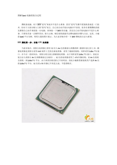
DIY攒机第一步:安装CPU处理器当前市场中,英特尔处理器主要有32位与64位的赛扬与奔腾两种(酷睿目前已经上市,酷睿处理器是英特尔采用0.65制作工艺的全新处理器,采用了最新的架构,同样采用LGA 775接口,在今后一段时间内,英特尔将全面主推酷睿处理器。
由于同样采用LGA 775接口,因此安装方法与英特尔64位奔腾赛扬完全相同)。
32位的处理器采用了478针脚结构,而64位的则全部统一到LGA775平台。
由于两者价格差距已不再明显,因此小编推荐新装机用户选择64位的LGA775平台,32位的478针脚已不再是主流,不值得购买。
上图中我们可以看到,LGA 775接口的英特尔处理器全部采用了触点式设计,与478针管式设计相比,最大的优势是不用再去担心针脚折断的问题,但对处理器的插座要求则更高。
这是主板上的LGA 775处理器的插座,大家可以看到,与针管设计的插座区别相当的大。
在安装CPU之前,我们要先打开插座,方法是:用适当的力向下微压固定CPU的压杆,同时用力往外推压杆,使其脱离固定卡扣。
压杆脱离卡扣后,我们便可以顺利的将压杆拉起。
接下来,我们将固定处理器的盖子与压杆反方向提起。
LGA 775插座展现在我们的眼前。
在安装处理器时,需要特别注意。
大家可以仔细观察,在CPU处理器的一角上有一个三角形的标识,另外仔细观察主板上的CPU插座,同样会发现一个三角形的标识。
Intel My wifi 安装与设置方法

最近自己安装intel的My wifi指示版出现了许多问题,网上寻找了好久,有好的答案,但都不能完全解决我的问题,而现在我自己搞定了。
所以想把自己安装的过程和遇到的问题写出来,供大家参考,希望能帮到大家。
要安装intel的My wifi指示版(安装旧版的也可以参考的),首先需要查看自己的无线网卡是不是intel的。
这个大家应该都懂吧。
直接到电脑的设备里,或是用鲁大师、驱动人生之类的软件也能看到。
先安装PROset,再安装仪表板安装英特尔®My WiFi指示板使用英特尔®PROSet/无线软件开始下载并安装英特尔PROSet无线软件: (这里的链接不一定是最新的哦)英特尔®My WiFi指示板15.1版.1要求英特尔®PROSet/无线软件15.1 .1版。
通过浏览器访问英特尔®PROSet/无线软件15.1 .1版。
下载32位或64位文件所要求的您的操作系统。
双击该文件下载。
该wireless_15.1.1_s32.exe或wireless_15.1.1_s64.exe。
按照说明安装该软件。
通过浏览器访问英特尔®My WiFi指示板15.1 .1版。
下载32位或64位文件所要求的您的操作系统。
intel_my_wifi_dashboard_15.1.1_s32.msi或intel_my_wifi_dashboard_15.1.1_s64.msi。
按照说明安装该软件。
安装完后出现lift的,或出现适配器无法找到的.需要到:打开网络和共享中心,更改适配器,选择无线网络不禁用连接上无法共享上网的,打开网络和共享中心活动网络,点进去,属性,选择允许共享网络,并选项是无线网络.这样应该能通过intel的无线网卡wifi技术上网了.这里说明下,不过你的电脑是通过网线还是无线路由链接的都能通过它共享网络.这是我个人摸索出来的经验.希望对大家有用.。
英特尔WiDi无线显示技术演讲稿

Page 19
英特尔无线显示技术目前已经发展到第三代,第三代英特尔 无线显示技术能够实现1080p全高清视频播放、3D环绕立 体声以及低于200毫秒延迟等特性。
轻松无线,放大精彩!
Intel Confidential – Internal & Intel Direct CNDA Agencies Only
专为此技术设计的 笔记本
• 搭载2010智能英特尔®酷 睿®家族处理器 ( i3/i5/i7 )拥有英特尔®高清显卡
• 基于HM55/HM57的高速 移动芯片组
• 搭载Intel® Centrino Advanced-N 6200/6300/1000的无线网 卡
• 除Windows 7 Basic以外的 所有Win7系统
实现高清多屏联动,使多人、多角度的内
容共享变得轻松惬意,是家庭共享、娱乐、
商务展示的最佳选择
02 通 过 英 特 尔 W i D i 扩 展 构 件,在一些合作软件中, 能够实现快速的连接 WiDi。
03
WiDi技术的使用模式也在不断扩
展,从家庭环境、到办公场所再
到教育情景,我们将见到越来越
多的WiDi使用实例。
英特尔®无线显示技术 轻松无线,放大精彩 * 需同时配备支持该技术的第三方电视适配器
Intel WiDi是如何工作的?
• 英特尔WiDi的技术优势
Intel Confidential – Internal & Intel Direct CNDA AgenciesPOagnley 5
Intel WiDi对软硬件的要求
1
目前,英特尔WiDi技术 已经全面支持笔记本、超 极本、一体电脑、平板甚 至是智能手机,前提是基 于英特尔芯片架构,支持 的大屏幕播放设备包括 H DT V 、 蓝 光 播 放 器 、 PS3游戏主机等等。
windows安装教程入门基本知识
windows安装教程入门根本知识Windows自带虚拟机安装教程。
Hyper-V限定专业版才能使用,家庭版是不能直接开启此功能的,可以以代码命令的方式调出来,同时要手动开启几个效劳和功能,比拟麻烦。
不过,这里提供一个小工具,一键更换任何喜欢的Windows版本(发送关键字获取)。
正式安装1、查看Windows版本2、Hyper-V默认关闭状态,需要开启,控制面板->程序->启动或关闭Windows功能->选择翻开Hyper-V。
3、虚拟系统安装。
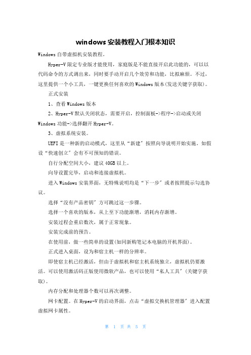
UEFI是一种新的启动模式,这里从“新建〞按照向导说明开始实施。
如假设“快速创立〞会有不可预知的错误。
自行分配空间大小,建议40GB以上。
向导设置完毕,启动和连接虚拟机。
进入Windows安装界面,无特殊说明均是“下一步〞或者按照提示勾选协议。
选择“没有产品密钥〞方可跳过这一步骤。
选择一个喜欢的版本,从上至下功能渐增,消耗内存渐增。
安装过程会重启数次,属于正常现象。
安装完成前的预告。
在使用前,做一些简单的设置(如同新购笔记本电脑的开机界面)。
正式进入桌面,设为和宿主机一样的分辨率。
即使宿主机已经激活,但由于虚拟机和宿主机系统独立,虚拟机仍要激活。
可以使用激活码正版使用微软产品,也可以使用“私人工具〞(关键字获取)。
内存分配和处理器个数可以再次调整。
网卡配置。
在Hyper-V的启动界面,点击“虚拟交换机管理器〞进入配置虚拟网卡属性。
在宿主机中进行设置网络共享,从控制面板->网络...依次进入。
宿主机和虚拟机版本较高的话,可以直接相互复制粘贴文件。
所有安装完毕。
一番折腾后,可以说,Hyper-V不管在性能还是功能性上,均比VMWare逊色,有点鸡肋。
如果虚拟机里安装的是Windows系列,那么速度还不错;如果安装的是Linu某(例如Ubentu),那么明显卡顿。
宿主机配置再不好的话,卡到移动鼠标都感觉不连贯那种。
Windows 10预览版安装指南日前,微软正式发布下一代桌面操作系统Windows10,并提供了技术预览版供所有用户下载。
安装Intel MY WIFI技术
如何安装intel最新的My WiFi管理工具
解决方案
Intel 5XXX以上系列的无线网卡支持intel最新开发的My WiFi无线技术,需要安装最新版本的intel 无线网卡驱动才能支持
下面以win7系统为例说明安装过程
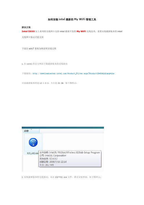
1.在intel的官方网站下载最新版本的无线驱动
下载地址:/Product_Filter.aspx?ProductID=3062&lang=zho
目前最新版本的是12.4.0.2,大小是28.2M,如下图所示:
2.安装最新版本的无线驱动,双击ICS-V32.exe文件,弹出安装界面,如下图所示:
然后点击“下一步”,弹出以下界面,点击“我接受该许可证协议中的条款”
点击“下一步”
下面会出现“典型”和“自定义”两种安装类型,这里需要注意,若要安装My WiFi技术,必须选择“自定义”安装类型,因为默认的典型安装方式不会安装该组件
点击“下一步”之后出现如下界面,默认的情况下My WiFi技术组件是未选择状态。
选择安装该功能的方法,点击“英特尔(R)PROSet/无线WiFi连接实用程序”选择“此功能及所有子功能将安装在本地硬盘驱动器上”点击“下一步”
选择好后的状态
然后是安装的过程,等待几分钟,
弹出如下界面,点击完成。
安装完成后在“控制面板”“程序和功能里面”有“英特尔(R)PROSet/无线WiFi软件”,如下图所示:
安装完后该软件默认状态是禁用的,在任务栏中会显示My WiFi图标,如下图所示:
启用该程序的方法,双击任务栏中的Intel My WiFi的图标,点击“启用”
启用后的状态
启用后的任务栏显示。
Intel软件的安装设置
Intel软件的安装设置Intel软件的安装设置1. Intel C++ /Fortran 编译器a) 版本 version 12.0 update 1 (也称作 Composer XE 2011)路径: /home_soft/soft/x86_64/intel/composerxe-2011.1.107/使⽤前设置:source /home_soft/soft/x86_64/intel/composerxe-2011.1.107/bin/compilervars.sh intel64常见使⽤命令 (替换 Makefile)icc 取代 gccicpc 取代 g++ifort 取代 g77,g95,gfortranxild 取代 ldxiar 取代 arb) ⽼版本 version 11.1路径 /home_soft/soft/x86_64/intel/Compiler/11.1/073/使⽤前设置source /home_soft/soft/x86_64/intel/Compiler/11.1/073/bin/iccvars.sh intel64source /home_soft/soft/x86_64/intel/Compiler/11.1/073/bin/ifortvars.sh intel64c) Intel Dedugger使⽤前source /home_soft/soft/x86_64/intel/composerxe-2011.1.107/bin/idbvars.sh intel64使⽤命令idbc (命令⾏)idb (图形界⾯,需要XWin⽀持)2. Intel Cluster Math Kernel Library 10.3 Update 1路径 /home_soft/soft/x86_64/intel/mkl使⽤前设置source /home_soft/soft/x86_64/intel/composerxe/mkl/bin/mklvars.sh intel64MKL linking 参数设置: /doc/815976554.html/en-us/articles/intel-mkl-link-line-advisor/如果使⽤Intel编译器 11.x 以后版本,可以直接使⽤ -mkl 选项⾃动链接对应的库⽂件3. Intel Integrated Performance Primitives 7.0 Update 1路径 /home_soft/soft/x86_64/intel/ipp使⽤前设置source /home_soft/soft/x86_64/intel/ipp/bin/intel64/ippvars_intel64.sh4. Intel Threading Building Block 3.0 Update 4路径 /home_soft/soft/x86_64/intel/tbb使⽤前设置source /home_soft/soft/x86_64/intel/tbb/bin/tbbvars.sh intel645. Intel InspectorXE 2011 ( = Intel Thread Checker)路径 /home_soft/soft/x86_64/intel/inspector_xe_2011使⽤命令/home_soft/soft/x86_64/intel/inspector_xe_2011/bin64/inspxe-cl (命令⾏)/home_soft/soft/x86_64/intel/inspector_xe_2011/bin64/inspxe-gui (图形界⾯)6. Intel VTune Amplifier XE 2011 ( = Intel VTune Analyzer + Intel Thread Profiler)路径 /home_soft/soft/x86_64/intel/vtune_amplifier_xe_2011使⽤命令/home_soft/soft/x86_64/intel/vtune_amplifier_xe_2011/bin64/amplxe-cl (命令⾏)/home_soft/soft/x86_64/intel/vtune_amplifier_xe_2011/bin64/amplxe-gui (图形界⾯,XWin)7. Intel MPI Library路径 /home_soft/soft/x86_64/intel/impi/4.0.1.007/bin64使⽤前设置source /home_soft/soft/x86_64/intel/impi/4.0.1.007/bin64/mpivars.sh8. Intel Cluster Toolkit ( = Intel Trace Analyzer and Colletor + Intel MPI + Intel C++/Fortran Compiler)路径 /home_soft/soft/x86_64/intel/itac使⽤前设置source /home_soft/soft/x86_64/intel/itac/8.0.0.011/bin/itacvars.shIII. 使⽤Intel软件编译MPI程序详细内容参考 "Intel MPI Library for Linux* OS Getting Started Guide"“Intel MPI Library for Linux* OS Reference Manual”1) 编译source /home_soft/soft/x86_64/intel/composerxe-2011.1.107/bin/compilervars.sh intel64source /home_soft/soft/x86_64/intel/impi/4.0.1.007/bin64/mpivars.shmpiicc –o myprog /test/test.cmpiicc 调⽤ Intel C 编译器mpiicpc 调⽤ Intel C++ 编译器mpiifort 调⽤ Intel Fortran 编译器mpicc / mpigcc 调⽤ gcc, ccmpifc / mpif90 调⽤ gfortranmpif77 调⽤ g772) 设置MPI缺省使⽤的Network Fabricexport I_MPI_FABRICS=ofa 所有进程使⽤Native InfiniBand* interface (OpenFabrics* Enterprise Distribution (OFED*) verbs) export I_MPI_FABRICS=shm:ofa 节点内进程使⽤shared memory,节点间进程使⽤OFED* verbsexport I_MPI_FABRICS=dapl 所有进程使⽤DAPL–capable network fabrics such as InfiniBand*, iWarp*, Dolphin*, and XPMEM* (through DAPL*)export I_MPI_FABRICS=shm:daplexport I_MPI_FABRICS=tcp 所有进程使⽤TCP/IP-capable network fabrics, such as Ethernet and InfiniBand* (through IPoIB*)export I_MPI_FABRICS=shm:tcp3) 运⾏mpirun -n <# of processes> ./myprog或者使⽤参数 -env I_MPI_FABRICS 选择需要运⾏的⽹络mpirun -genv I_MPI_FABRICS shm:ofa -n <# of processes> ./myprogmpirun 会⾃动调⽤mpdboot, mpiexec, 和mpdallexit命令。
Intel Dialogic D 41JCT-LS PCI安装卡快速安装指南说明书
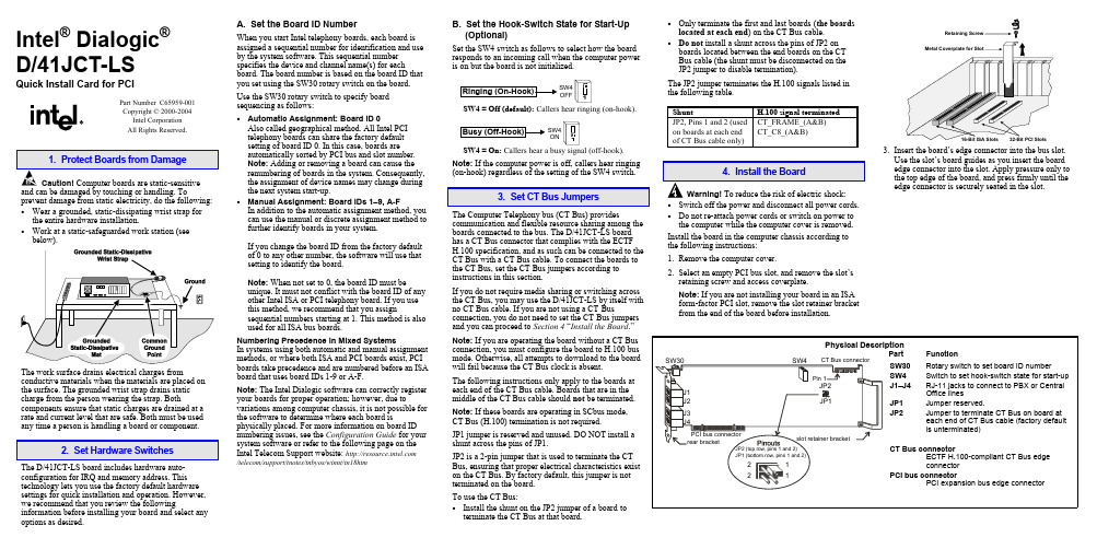
Intel® Dialogic®D/41JCT-LSQuick Install Card for PCIPart Number C65959-001Copyright © 2000-2004Intel CorporationAll Rights Reserved.prevent damage from static electricity, do the following:• Wear a grounded, static-dissipating wrist strap forthe entire hardware installation.• Work at a static-safeguarded work station (seebelow).The work surface drains electrical charges from conductive materials when the materials are placed on the surface. The grounded wrist strap drains static charge from the person wearing the strap. Both components ensure that static charges are drained at a rate and current level that are safe. Both must be used any time a person is handling a board or component.2. Set Hardware SwitchesThe D/41JCT-LS board includes hardware auto-configuration for IRQ and memory address. This technology lets you use the factory default hardware settings for quick installation and operation. However, we recommend that you review the following information before installing your board and select any options as desired.A. Set the Board ID NumberWhen you start Intel telephony boards, each board isassigned a sequential number for identification and useby the system software. This sequential numberspecifies the device and channel name(s) for eachboard. The board number is based on the board ID thatyou set using the SW30 rotary switch on the board.Use the SW30 rotary switch to specify boardsequencing as follows:• Automatic Assignment: Board ID 0Also called geographical method. All Intel PCItelephony boards can share the factory defaultsetting of board ID 0. In this case, boards areautomatically sorted by PCI bus and slot number.Note: Adding or removing a board can cause therenumbering of boards in the system. Consequently,the assignment of device names may change duringthe next system start-up.• Manual Assignment: Board IDs 1–9, A-FIn addition to the automatic assignment method, youcan use the manual or discrete assignment method tofurther identify boards in your system.If you change the board ID from the factory defaultof 0 to any other number, the software will use thatsetting to identify the board.Note: When not set to 0, the board ID must beunique. It must not conflict with the board ID of anyother Intel ISA or PCI telephony board. If you usethis method, we recommend that you assignsequential numbers starting at 1. This method is alsoused for all ISA bus boards.Numbering Precedence in Mixed SystemsIn systems using both automatic and manual assignmentmethods, or where both ISA and PCI boards exist, PCIboards take precedence and are numbered before an ISAboard that uses board IDs 1-9 or A-F.Note: The Intel Dialogic software can correctly registeryour boards for proper operation; however, due tovariations among computer chassis, it is not possible forthe software to determine where each board isphysically placed. For more information on board IDnumbering issues, see the Configuration Guide for yoursystem software or refer to the following page on theIntel Telecom Support website: /telecom/support/tnotes/tnbyos/winnt/tn18htmB. Set the Hook-Switch State for Start-Up(Optional)Set the SW4 switch as follows to select how the boardresponds to an incoming call when the computer poweris on but the board is not initialized.SW4OFFSW4 = Off (default): Callers hear ringing (on-hook).SW4ONSW4 = On: Callers hear a busy signal (off-hook).Note: If the computer power is off, callers hear ringing(on-hook) regardless of the setting of the SW4 switch.3. Set CT Bus JumpersThe Computer Telephony bus (CT Bus) providescommunication and flexible resource sharing among theboards connected to the bus. The D/41JCT-LS boardhas a CT Bus connector that complies with the ECTFH.100 specification, and as such can be connected to theCT Bus with a CT Bus cable. To connect the boards tothe CT Bus, set the CT Bus jumpers according toinstructions in this section.If you do not require media sharing or switching acrossthe CT Bus, you may use the D/41JCT-LS by itself withno CT Bus cable. If you are not using a CT Busconnection, you do not need to set the CT Bus jumpersand you can proceed to Section 4 “Install the Board.”Note: If you are operating the board without a CT Busconnection, you must configure the board to H.100 busmode. Otherwise, all attempts to download to the boardwill fail because the CT Bus clock is absent.The following instructions only apply to the boards ateach end of the CT Bus cable. Boards that are in themiddle of the CT Bus cable should not be terminated.Note: If these boards are operating in SCbus mode,CT Bus (H.100) termination is not required.JP1 jumper is reserved and unused. DO NOT install ashunt across the pins of JP1.JP2 is a 2-pin jumper that is used to terminate the CTBus, ensuring that proper electrical characteristics existon the CT Bus. By factory default, this jumper is notterminated on the board.To use the CT Bus:• Install the shunt on the JP2 jumper of a board toterminate the CT Bus at that board.• Only terminate the first and last boards(the boardslocated at each end) on the CT Bus cable.• Do not install a shunt across the pins of JP2 onboards located between the end boards on the CTBus cable (the shunt must be disconnected on theJP2 jumper to disable termination).The JP2 jumper terminates the H.100 signals listed inthe following table.Shunt H.100 signal terminatedJP2, Pins 1 and 2 (usedon boards at each endof CT Bus cable only)CT_FRAME_(A&B)CT_C8_(A&B)4. Install the BoardWarning!To reduce the risk of electric shock:• Switch off the power and disconnect all power cords.• Do not re-attach power cords or switch on power tothe computer while the computer cover is removed.Install the board in the computer chassis according tothe following instructions:1.Remove the computer cover.2.Select an empty PCI bus slot, and remove the slot’sretaining screw and access coverplate.Note: If you are not installing your board in an ISAform-factor PCI slot, remove the slot retainer bracketfrom the end of the board before installation.Retaining3.Insert the board’s edge connector into the bus slot.Use the slot’s board guides as you insert the boardedge connector into the slot. Apply pressure only tothe top edge of the board, and press firmly until theedge connector is securely seated in the slot.4.Replace and tighten the retaining screw to secure the board. If the screw is not installed and you attach a CT Bus cable to the board, the board may be accidentally unseated from the slot.5.To install an additional board, select an empty PCI slot adjacent to the location of the previous board,and repeat (the second part of) step 2 through step 4.5. Attach CT Bus Cable to BoardThe instructions in this section only apply if you are using CT Bus to connect boards. If you are using the board without a CT Bus connection, skip this section.Use a CT Bus cable to connect your board to other Caution! To preserve the electrical integrity of number of connectors (“drops”). It is recommended that no more than two connectors be left unused at either end of the cable. In addition, it is preferable to distribute the installed boards in slots along the length of the CT Bus cable rather than clustered in one area.Attach the CT Bus cable to the Intel telephony boards as follows:1.Attach the end connector on the CT Bus cable to the CT Bus edge connector on the top edge of the first board in the sequence. The connectors are designed to fit together one way only. If the connector does not seat fully on the board, turn the cable around and try again. Make sure that the colored stripe on the cable faces the rear bracket.2.Attach the cable to the next board until all boards are connected by the cable.3.If the cable has extra connectors or is loose, tuck the cable down so that it does not snag when you replace the computer cover. See the Caution given earlier in this section.6. Connect CT Bus/SCbus Adapter (optional)If you are using only CT Bus boards, or are using the board without a CT Bus connection, skip the instructions in this section.To connect your board to SCbus form-factor boards, use the CT Bus/SCbus adapter. You may use only one CT Bus/SCbus adapter per system .1.Before installing the adapter, the Dialogic boards in your chassis must be positioned in the correct order.The board on which the adapter is installed must be inserted in the first PCI slot adjacent to an ISA slot.Locate this board.2.Align pin 1 of the adapter with pin 1 of the edge connector on the board. Press the adapter onto the board with the SCbus cable connector facing the rearedge of the board.CT Bus / SCbusFor more information, see the hardware installation instructions for the CT Bus/SCbus Adapter.7. Complete Board InstallationAfter you have installed the board(s) and connected the CT Bus cable (and SCbus adapter, if appropriate)replace the computer cover and re-connect power cord.8. Connect External CablesEach RJ-11 jack on the rear bracket of the voice board supports a single voice channel. Use each RJ-11 jack and phone cable to connect each channel to an analog PBX or standard telephone outlet.Since this board emulates a standard telephone, a standard telephone will not function when directlyattached to the board.Note: Connect the Earth Recall signal to pin 2. DONOT connect Tip or Ring lines to pin 2 or improper operation of the D/41JCT-LS will result.9. Install Software, Configure and TestInstall the Intel Dialogic software release and configure the boards as described in the Installation Guide and Configuration Guide for your system software release.Your application software or Intel Dialogic software release may have special installation or configuration requirements. Be sure to read your softwaredocumentation including release note information before you install the software.Note: If you are adding hardware to an existing system,you do not need to uninstall existing Intel Dialogic software.For technical specifications and product information,see the Intel Telecom Products website at/design/network/products/telecom .Direct Return Authorization (DRA)If you are a reseller and are located in the Americas,you may return a board for warranty repair by using the online DRA form at/support/motherboards/draform.htm .For all other returns, contact your vendor or Intel Customer Support (for more information, see /support/9089.htm ).。
- 1、下载文档前请自行甄别文档内容的完整性,平台不提供额外的编辑、内容补充、找答案等附加服务。
- 2、"仅部分预览"的文档,不可在线预览部分如存在完整性等问题,可反馈申请退款(可完整预览的文档不适用该条件!)。
- 3、如文档侵犯您的权益,请联系客服反馈,我们会尽快为您处理(人工客服工作时间:9:00-18:30)。
英特尔® 无线显示技术安装配置手册
一、系统软硬件需求
硬件要求:
支持英特尔®全新酷睿™ 处理器系列 (只支持标准电压型号)
Intel® Core™ i3 mobile processor
Intel® Core™ i5 mobile processor
Intel® Core™ i7 mobile processor
支持英特尔®高清显卡
Intel® HD Graphics(Integrated only)
支持英特尔® 5 系列芯片组
Mobile Intel HM57 Chipset
Mobile Intel HM55 Chipset
Mobile Intel QM57 Chipset
Mobile Intel QS57 Chipset
支持英特尔® 无线网络解决方案
Intel® Centrino® Advanced-N 6200
Intel® Centrino® Advanced-N + WiMAX 6250
Intel® Centrino® Ultimate-N 6300
Intel® Centrino Wireless-N 1000
软件要求:
支持的操作系统
Windows* 7 32-bit Home Basic
Windows* 7 64-bit/32-bit Home Premium
Windows* 7 64-bit/32-bit Ultimate
Windows* 7 64-bit/32-bit Pro
需要的软件环境
Intel® 芯片组驱动程序
Intel® 高清显卡驱动 15.17.2.64.2102 或更高版本
Intel® 无线网卡驱动程序 13.2.0 或更高版本, Intel MWT enabled
Intel® 无线显卡技术软件 1.2.14 或更高版本
显示分辩率要求:
支持的分辩率
1280x720
1280x768
1366x768
接口要求:
HDMI接口
色差分量接口
二、安装英特尔无线显示软件
安装驱动程序
1. 将电脑升级到最新的BIOS版本
2. 安装 Windows 7 操作系统
3. 安装最新英特尔芯片组驱动程序
4. 安装英特尔高清显卡驱动程序
5. 安装英特尔无线网卡驱动程序
注意:英特尔MWT功能必须启动
6. 安装其它所有的系统驱动程序(如网卡、声卡…)
安装英特尔无线显示软件
1. 将英特尔无线显示软件先拷贝到硬盘或者USB硬盘上(安装时需要有解压缩操作,存储盘必须是可写入的)
2. 点击 setup.exe 文件启动安装
3. 按照默认提示完成安装(图示如下)
二、无线显示设备连接
1. 先确认无线网络是连通的(通过英特尔无线网络管理软件或其它各种管理软件)
注意:如果操作系统提示需要定义网络为“私有网络”还是“公共网络”时,选
择“私有网络”
2. 启动英特尔无线显示软件
3. 选择接受 license agreement,如下图所示
4. 应用程序会自动扫描无线接受装置(目前为Netgear的无线媒体盒),并列在表里
5. 双击需要连接的无线媒体盒开始进行连接,如下图所示
6. 根据电视上的提示输入4位数的认证码,将其输入到电脑端的界面里,并点击“继续”
注意:如果成功连接,电脑桌面应该在5~10秒内同步显示到电视上
7. 点击OK返回到主界面上
8. 点击无线媒体盒子的Properties 按钮,再选定“Automatically
connect to this adapter”
9. 点击OK返回主页面
至此,英特尔无线显示设备的设置就已经成功完成了。
如果断开连接,只需要在电脑端点击“Disconnect”按钮即可。