
JST-VL系列图纸中文版
VL CONNECTOR
■登录标准
0 L JS T a
:Recognized E 60389 :Certified LR 20812 :R9351103
■一般规格
●额定电流 : 20A AC/DC(请参阅下表) ●额定电压 : 600V AC/DC ●使用温度范围 : -25℃~ +90℃(含通电时的温度上升值) ●接触电阻 : 初 期 /7mΩ 以下 环境试验后 /10mΩ 以下 ●绝缘电阻 : 1,000MΩ 以上 ●耐电压 : AC 2,000V/1 分钟 ●适用电线范围 : AWG#22 ~ #12 ●适合的印刷电路板厚度 : 1.6mm
— —
端子 SVF-81T-P2.0
压着机
AP-K2N
压着模具 压着模具主体
MKS-L —
刀刃
MK/SVF/M-81-20 —
压着模具套件
APLMK SVF/M81-20 —
MK/SVF/M-42-20 APLMK SVF/M42-20 MK/SVF/M-61-20 APLMK SVF/M61-20
4
VL CONNECTOR
塑壳孔编号
内部锁定
〈2 极〉 〈3 极〉 〈4 极〉 〈6 极〉
〈8 极〉
〈12 极〉
/-67
/-67
/-67
/-67
/-67
䚼䫕ᅮ
ᵕ᭄
2 3 4 4˄ऩᥦ˅ 6 8 12
ൟো VLP-02V-1 VLP-03V-1 VLP-04V-1 VLP-04VN-1 VLP-06V-1 VLP-08V-1 VLP-12V-1 ᴤ䋼
ሐ啭ǃ8/9ˈ✊㡆˄ⱑ㡆˅
〈8 极〉
〈12 极〉
ݙ䚼䫕ᅮ
ᵕ᭄
2 3 4 6 8 12
ൟো VLP-02V VLP-03V VLP-04V VLP-06V VLP-08V VLP-12V ᴤ䋼
ሐ啭ǃ8/9ˈ✊㡆˄ⱑ㡆˅
᭄䞣㹟
●符合 RoHS 标准的产品
〈4 极(单排)/8 极〉
〈12 极〉
带座插头
〈2/3 极〉
%
〈4/6 极〉
%
$
$
〈4(单排)极〉
4 4 4 3 3 3
※ 使用时,请参阅卷首的“端子 / 连接器”使用注意事项。 ※ 详情请垂询本公司。 ※ 介绍了符合 RoHS 标准的产品。
〈2/3/4(单排)极〉
˄˅ $ f ˄ऩᥦ˅ᵕ˖¶f ǃᵕ˖¶f f PLQ
〈4/6/8/12 极〉
下表 请避免将超出每 1 极额定电流的电流(例 : 3 极、使用 #12 时为 17A 以上) 进行并联分流使用,否则会导致电流失衡等问题。不得已而分流使用时, 请在设计时为每条电路留出足够的余量,以免发生电路失衡现象。 ■ 额定电流因塑壳的极数与压着的电线而异。 各塑壳、电线的额定电流如下所示。
该产品是适用于大电流、可使用 6.2mm 间距电线对电线连 接与电线对电路板连接这 2 种连接类型的连接器。可使用 防止端子不完全插入及脱落的固定器,安全可靠地连接大 电流电路。
外部锁定
〈4 极(单排) 〉 〈2 极〉 〈3 极〉 〈4 极〉 〈6 极〉 〈8 极〉
/-67
〈12 极〉
/-67
/-67
/-67
/-67
/-67
/-67
/-67
/-67
型号标示方法
端子 塑壳
S V F - 42 T - P 2.0
ѻકᔶᗕ˖6Ă䫒⢊ǃ%Ăᬷᢝ ㋏߫ৡ ᔶ⢊˖)Ăᦦᑻッᄤ 䗖⫼⬉㒓㣗ೈ˖Ă$:*̚ Ă$:*̚ Ă$:* 㸼䴶໘⧚˖7Ă䬔䫵˄ಲ⌕⛞໘⧚˅ ᴤ䋼˖3Ă⻋䴦䪰 ッᄤሎᇌ ㋏߫ৡ 䳊䚼ӊৡ鹵˖ᦦ༈ ᵕ᭄˖ǃǃǃǃǃ 䰏➗ᗻᷛ䆄˖9Ă8/9 ᔶ⢊˖᮴Ăݙ䚼䫕ᅮĂ䚼䫕ᅮ
500 500 500 500 200 100
●符合 RoHS 标准的产品
/-67
/ǂ -67
/-67
2
VL CONNECTOR
塑壳
〈2 极〉
˄˅ $ f ¶f ˄˅ PLQ f PLQ PLQ
内部锁定型
f
内部锁定型
˄˅
˄˅
外部锁定型
˄˅
外部锁定型
注 1)上图是从焊接侧看到的图。 2)电路板开孔的公差整体为 ±0.05,不得层叠。 3)电路板的开孔尺寸因电路板的类型与开孔方法等而异。 上图尺寸仅为参考值,详情请垂询本公司。
1
˄˅
˄˅
VL CONNECTOR
端子
ൟো
䗖⫼⬉㒓㣗ೈ $:* PP
0.3 ̚1.25 0.5 ̚2.0 3.5 22̚16 20̚14 12
⬉㒓Ⲃᕘ˄PP˅
1.7 ̚3.2 1.9 ̚3.4 4.1
᭄䞣 ो
2,000 2,000 2,000
$
ሎᇌ˄PP˅ %
13.4 19.6 13.4 26.2 19.6 26.2 38.6
᭄䞣ㆅ
100 100 100 100 50 50 40
6.2 12.4 6.2 18.6 12.4 18.6 31.0
ᦦ༈˖䪰ড়䞥ǃ䬔䫵˄ಲ⌕⛞໘⧚˅ ᑩᑻ˖ሐ啭ǃ8/9ˈ✊㡆˄ⱑ㡆˅
●符合 RoHS 标准的产品
/-67
〈3 极〉
〈4 极〉
〈4 极(单排) 〉
/-67 /-67
〈6 极〉
〈8 极〉
〈12 极〉
/-67
᭄䞣㹟
500 500 500 500 500 200 100
●符合 RoHS 标准的产品
3
/-67
/-67
/-67
ĆSVF-42T-P2.0 ǂSVF-61T-P2.0 ǂSVF-81T-P2.0
ᴤ䋼ǃ㸼䴶໘⧚
⻋䴦䪰ǃ䬔䫵˄ಲ⌕⛞໘⧚˅
●符合 RoHS 标准的产品 ※ 表示未注册 T V 标准的产品。
端子 SVF-42T-P2.0
压着机
压着模具 压着模具主体
MKS-L — MKS-L —
刀刃
— —
压着模具套件
VL P - 02 V - 1
带座插头
固定器
B 02P - VL
VL S - 02 V
㋏߫ৡ 㒘㺙કᔶᗕ˖%Ă乊㺙ൟ ᵕ᭄˖ǃǃǃǃǃ ㋏߫ৡ 䳊䚼ӊৡ鹵˖ᅮ఼ ᵕ᭄˖ǃǃǃǃǃ 䰏➗ᗻᷛ䆄˖9Ă8/9
5
AP-K2N
SVF-61T-P2.0
注)有关全自动压着机用的压着模具,请垂询本公司。
塑壳
〈2 极〉
/-67
〈3 极〉
〈4 极〉
/ǂ -67
〈6 极〉
/ǂ -67
%
〈8/12 极〉
%
$
$
ᵕ᭄
2 3 4 4˄ऩᥦ˅ 6 8 12
ൟো B02P-VL B03P-VL B04P-VL B04P-VL-VN-1.8 B06P-VL B08P-VL B12P-VL ᴤ䋼ǃ㸼䴶໘⧚
●塑壳锁扣方式 ●固定器 ●适用于大电流通电 ●适用 2 种连接
⬉⌕ऩԡ˄$˅
ᵕ᭄
#12
#14
Փ⫼⬉㒓ሎᇌ$:* #16 #18
#20
#22
2 3 4 6 8 12
20 17 16 15 14 13
15 14 13 12 11 10
10 9 9 8 7 7
8 8 7 7 6 6
6 6 6 5 5 4
VL CONNECTOR
固定器
〈2/4 极〉
〈3/6 极〉
ᵕ᭄
2g4 3g6 4˄ϔ߫˅g8 12
ൟো VLS-02V VLS-03V VLS-08V VLS-12V ᴤ䋼
᭄䞣㹟
1,000 1,000 1,000 1,000
⦏⩗㑸㓈ᔎሐ啭ǃ8/9ˈ✊㡆˄䈵⠭㡆˅
JQZ-II系列安装图

公路、市政及 及轨道交 交通工 工程 程建设 设 桥梁 桥梁构件 件通 通用设 设计 计图 JQ QZ 系列球型钢 钢支 支座 座通 通用 用安 安装 装图 图( 号:JQZ(图号 -Ⅱ) ) 第二 二册 第 册 第一册 共三册 册 系列 列 JQZ-Ⅰ系★ 第二 二册 JQZJ -Ⅱ系 系列 第 册 第三册 JQZ Z-Ⅲ系 系列 列2 2009 年 8 月· ·西安 安 图 纸 目 录 序号 1 2 3 4 5 图 号 JQZ-01 JQZ-Ⅱ-01 JQZ-Ⅱ-02 JQZ-Ⅱ-03 JQZ-Ⅱ-04图 名 设 计 说 明 JQZ 球型钢支座(JQZ-Ⅱ)安装图固定支座系列(一) JQZ 球型钢支座(JQZ-Ⅱ)安装图纵向活动支座系列(二) JQZ 球型钢支座(JQZ-Ⅱ)安装图横向活动支座系列(三) JQZ 球型钢支座(JQZ-Ⅱ)安装图多向活动支座系列(四)页 次 1~3 4 5 6 7 JQZ 系列球型钢支座 图号:JQZ-01设 计 说 明1 总 则JQZ 系列球型钢支座是按照国家标准,同时参照并满足欧洲标准进行设计,适用于公路、 市政及轨道交通的各类弯、坡、大跨及复杂桥梁。
4支座代号JQZ-6000-ZX-e100-Ⅱ-C C 表示常温型,F 表示耐寒型 Ⅰ表示水平承载力为竖向力的 10% Ⅱ表示水平承载力为竖向力的 15% Ⅲ表示水平承载力为竖向力的 22.5% 支座滑动方向位移量(mm) DX 表示多向活动支座 ZX 表示纵向活动支座 HX 表示横向活动支座 GD 表示固定支座 设计竖向承载力(kN) 球型钢支座代号 本例表示竖向承载力为 6000kN, 位移量为 100mm 的 JQZ 系列纵向活动常温型球型钢支座。
CookTek-全系列图纸-全系列图纸-201
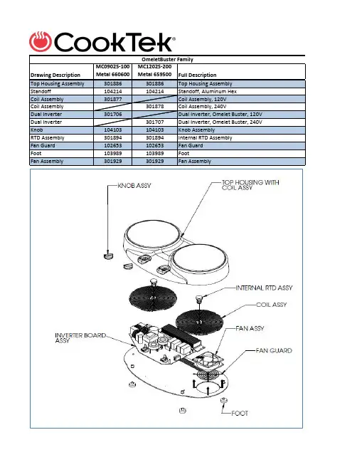
Drawing Description MC0902S-100Metal 660600MC1202S-200Metal 659500Full DescriptionTop Housing Assembly301886301886Top Housing AssemblyStandoff104214104214Standoff, Aluminum HexCoil Assembly301877Coil Assembly, 120VCoil Assembly301878Coil Assembly, 240VDual Inverter301706Dual Inverter, Omelet Buster, 120V Dual Inverter301707Dual Inverter, Omelet Buster, 240V Knob104103104103Knob AssemblyRTD Assembly301894301894Internal RTD AssemblyFan Guard102653102653Fan GuardFoot103989103989FootFan Assembly301929301929Fan AssemblyOmeletBuster FamilyDrawing DescriptionMC1800MC2500MC3000MC3500Full Description Top Housing with Glass301020301020301020301020Housing Assy, CT, FS, 1H LED Display Assy300531300531300531300531LED Assy, PCB, (18" Cable)Control Button Assy/Potentiometer Assy 300582300582300582300582Potentiometer Assy, Gen II, CT, FS, 18"Control Knob100839100839100839100839Control Knob Overlay101179101179101179101179Overlay, Face Plate, Free Standing Units Nylon Coil Spacer101447101447Spacer, Nylon, Tapped Nylon Coil Spacer101448Spacer, Nylon, Tapped Nylon Coil Spacer101446Spacer, Nylon, Tapped Coil Assy300777Coil Assy, Gen II, CT, FS/DI, 1H, 120v Coil Assy300495300495300495Coil Assy, Gen II, CT, FS/DI, 1H, 240v Internal RTD Assy300557300557300557300557RTD Assy, Internal, CT Nylon Coil Standoff102824102824102824102824Standoff, Nylon, 3.35L Inverter Board Assy301225Inverter Board Assy, 120v Inverter Board Assy301226301226301226Inverter Board Assy, 240v Cpu Assy (add Programming)300969300969300969300969CPU Assy w/rfid, W/processor & Program 102954 (120 v ) or 102955 (240 v )Fan Assy301109Fan Assy, Tube Axial, Low Power, 12VDC 0.44A (92X92X32 MM)Fan Assy301110301110301110Fan Assy, Tube Axial, High Power, 12VDC 0.77A (92X92X32 MM)Fan Guard102653102653102653102653Fan Guard, 3.25 x 3.25Grease Filter103307103307103307103307Filter, Grease, 4.520 x 4.520 x 0.343"Foot 103338103338103338103338Foot, Appliance, 1.25"MC Heritage FamilyDrawing DescriptionMCD1800MCD2500MCD3000MCD3500Full Description Top Housing with Glass 300567300567300567300567Frame Assy, Gen II, CT, DI, 1H LED Assy300531300531300531300531LED Assy, PCB, (18" Cable)E-Filter Board301162301162301162301162Fixed Board Assy, Efilter w/adhesive Nylon Coil Spacer 1014991014992x 101499Spacer, Nylon, Tapped Nylon Coil Spacer 1013222x 101322101322Spacer, Nylon, Tapped Coil Assy300777Coil Assy, Gen II, CT, FS/DI, 1H, 120v Coil Assy300495300495300495Coil Assy, Gen II, CT, FS/DI, 1H, 240v Internal RTD Assy 300557300557300557300557RTD Assy, Internal, CT Nylon Coil Standoff 102824102824102824102824Standoff, Nylon, 3.35L Inverter Board Assy 301225Inverter Board Assy, All 120v Inverter Board Assy 301226301226301226inverter Board Assy, All 240v Cpu Assy Programmed 300969300969300969300969CPU Assy w/rfid, W/processor & program Fan Assy301109Fan Assy, Tube Axial, Low Power, 12VDC 0.44A (92X92X32 MM)Fan Assy301110301110301110Fan Assy, Tube Axial, High Power, 12VDC 0.77A (92X92X32 MM)Fan Guard102653102653102653102653Fan Guard, 3.25 x 3.25Control Box Assy 300532300532300532300532Control Box Assy, Gen II, CT, DI, 1H Overlay100974100974100974100974Overlay, Face Plate, Control Box Potentiometer Assy 300529300529300529300529Potentiometer Assy, Gen II, CT, DI Control Knob100839100839100839100839Control Knob Control Cable 300585300585300585300585Cable Assy, For Control Box, 7 Conductor, 42"LMCD Heritage Drop-In FamilyDrawing Description MC2502FMC3002F MC3502F Full Description Top Housing with Glass 301042301042301042Housing Assy, CT, FS, 2H, FB LED Assy 18"300531300531300531LED Assy, PCB, 18" Cable Front Hob LED Assy 36"300621300621300621LED Assy, PCB, 36" Cable Back Hob Overlay101176101176101176Overlay, Face Plate, Free Standing Units Potentiometer Assy 300582300582300582Potentiometer Assy, Gen II, CT, FS, 18" Front Hob Potentiometer Assy 300648300648300648Potentiometer Assy, Gen II, CT, FS, 36" Back Hob Control Knob100839100839100839Control Knob E-Filter Board Assy 301162301162301162Fixed Board Assy, Efilter w/adhesive Nylon Coil Spacer 2x 101322101322Spacer, Nylon, Tapped Nylon Coil Spacer 1014992x 101499Spacer, Nylon, Tapped Coil Assy300495300495300495Coil Assy, Gen II, CT, FS/DI, 1H, 120v/240v Internal RTD Assy 300557300557300557RTD Assy, Internal, CT Nylon Coil Standoff 102824102824102824Standoff, Nylon, 3.35L Inverter Board Assy 301226301226301226Inverter Board Assy, All 240v (new)CPU Assy300969300969300969CPU Assy w/rfid, W/processor & program Fan Assy301110301110301110Fan Assy, Tube Axial, Low Power/High Power, 12VDC 0.77A Fan Guard102653102653102653Fan Guard, 3.25 x 3.25Grease Filter103307103307103307Filter, Grease, 4.520 x 4.520 x 0.343"Foot 103338103338103338Foot, Appliance, 1.25"MCF Heritage 2-Hob F/B FamilyDrawing Description MC2502SMC3002S MC3502S Full Description Top Housing with Glass 301045301045301045Housing Assy, CT, FS, 2H, SS LED Assy300531300531300531LED Assy, PCB, 18" Cable Overlay101345101345101345Overlay, Face Plate, Free Standing Units Potentiometer Assy 300582300582300582Potentiometer Assy, Gen II, CT, FS, 18"Control Knob100839100839100839Control Knob E-Filter Board Assy 301162301162301162Fixed Board Assy, Efilter w/adhesive Nylon Coil Spacer 2x 101322101322Spacer, Nylon, Tapped Nylon Coil Spacer 1014992x 101499Spacer, Nylon, Tapped Coil Assy300495300495300495Coil Assy, Gen II, CT, FS/DI, 1H, 120v/240v Internal RTD Assy 300557300557300557RTD Assy, Internal, CT Nylon Coil Standoff 102824102824102824Standoff, Nylon, 3.35L Inverter Board Assy 301226301226301226Inverter Board Assy, All 240v (new)CPU Assy300969300969300969CPU Assy w/rfid, W/processor & program Fan Assy301110301110301110Fan Assy, Tube Axial, Low Power/High Power, 12VDC 0.77A Fan Guard102653102653102653Fan Guard, 3.25 x 3.25Grease Filter103307103307103307Filter, Grease, 4.520 x 4.520 x 0.343"Foot 103338103338103338Foot, Appliance, 1.25"MCS Heritage 2-Hob S/S FamilyDrawing Description MCD2502FMCD3002F MCD3502F Full Description Top Housing with Glass 301047301047301047Housing Assy, Gen III, CT, DI, 2H, FB LED Assy 18"300531300531300531LED Assy, PCB, (18" Cable) Front LED Assy 36"300621300621300621LED Assy, PCB, (36" Cable) Rear E-Filter Board Assy 301162301162301162Fixed Board Assy, Efilter w/adhesive Nylon Coil Spacer 2x 101322101322Spacer, Nylon, Tapped Nylon Coil Spacer 1014992x 101499Spacer, Nylon, Tapped Coil Assy300495300495300495Coil Assy, Gen II, CT, FS/DI, 1H, 120v/240v Internal RTD Assy 300557300557300557RTD Assy, Internal, CT Nylon Coil Standoff 102824102824102824Standoff, Nylon, 3.35L Inverter Board Assy 301226301226301226Inverter Board Assy, All 240v (new)CPU Assy300969300969300969CPU Assy w/rfid, W/processor & program Fan Assy301110301110301110Fan Assy,Tube Axial,Low Power/High Power,12VDC 0.77A Fan Guard102653102653102653Fan Guard, 3.25 x 3.25Control Box Assy 300683300683300683Control Box Assy, Gen II, CT, DI, 2H, FB Control Knob 100839100839100839Control Knob Overlay101373101373101373Overlay, Control Box, FB, 2 HOB Commercial Potentiometer Assy300529300529300529Potentiometer Assy, Gen II, CT, DI Control Cable 300585300585300585Cable Assy, For Control Box, 7 Conductor, 42"LMCDF Heritage Drop-In F/B FamilyDrawing DescriptionMCD2502S MCD3002S MCD3502S Full Description Top Housing with Glass 301049301049301049Housing Assy, Gen III, CT, DI, 2H, FB LED Assy300531300531300531LED Assy, PCB, 18" Cable E-Filter Board Assy 301162301162301162Fixed Board Assy, Efilter w/adhesive Nylon Coil Spacer 2x 101322101322Spacer, Nylon, Tapped Nylon Coil Spacer 1014992x 101499Spacer, Nylon, Tapped Coil Assy300495300495300495Coil Assy, Gen II, CT, FS/DI, 1H, 120v/240v Internal RTD Assy 300557300557300557RTD Assy, Internal, CT Nylon Coil Standoff 102824102824102824Standoff, Nylon, 3.35L Inverter Board Assy 301226301226301226Inverter Board Assy, All 240v (new)CPU Assy300969300969300969CPU Assy w/rfid, W/processor & program Fan Assy301110301110301110Fan Assy,Tube Axial,Low Power/High Power,12VDC 0.77A Fan Guard102653102653102653Fan Guard, 3.25 x 3.25Control Box Assy 300702300702300702Control Box Assy, Gen II, CT, DI, 2H, FB Control Knob 100839100839100839Control Knob Overlay101215101215101215Overlay, Control Box, SS, 2 HOB Commercial Potentiometer Assy300529300529300529Potentiometer Assy, Gen II, CT, DI Control Cable 300585300585300585Cable Assy, For Control Box, 7 Conductor, 42"LMCDS Heritage Drop-In S/S FamilyMCG Apogee FamilyDrawing Description MC1800G MC2500G MC3000G MC3500G Full DescriptionHousing Assy301097301097301097301097Housing Assy, Apogee CT FS 1HLCD Display Assy301358301358301358301358Display Module Assy, Apogee Single, New Haven Nylon Coil Spacer101447101447Spacer, Hex Nylon TapeNylon Coil Spacer101448Spacer, Hex Nylon TapeNylon Coil Spacer101446Spacer, Hex Nylon TapeCoil Assy300777Coil Assy, Gen II, CT, FS/DI, 1H, 120vCoil Assy300495300495300495Coil Assy, Gen II, CT, FS/DI, 1H, 240vInternal RTD Assy300557300557300557300557RTD Assy, Internal, CTNylon Coil Standoff102824102824102824102824Standoff, Nylon, 3.35LInverter Board Assy301225Inverter Board Assy, All 120vInverter Board Assy301226301226301226Inverter Board Assy, All 240vCPU Assy301077301077301077301077CPU Assy, W/touch panel and LCD capabilities - Apogee Fan Assy301109Fan Assy, Tube Axial, Low Power, 12VDC 0.44AFan Assy301110301110301110Fan Assy, Tube Axial, High Power, 12VDC 0.77AFan Guard102653102653102653102653Fan Guard, 3.25 x 3.25Grease Filter103307103307103307103307Filter, Grease, 4.520 x 4.520 x 0.343"Foot103338103338103338103338Foot, Appliance, 1.25"Drawing Description MCD1800GMCD2500G MCD3000G MCD3500G Full Description Housing Assy 301101301101301101301101Housing Assy, Apogee Buffet LCD Display Assy 301150301150301150301150Display Module Assy, Apogee, New Haven Nylon Coil Spacer 101447Spacer, Hex Nylon Tape Nylon Coil Spacer 101446101446101446Spacer, Hex Nylon Tape Coil Assy300777Coil Assy, Gen II, CT, FS/DI, 1H, 120v Coil Assy300495300495300495Coil Assy, Gen II, CT, FS/DI, 1H, 240v Internal RTD Assy 300557300557300557300557RTD Assy, Internal, CT Nylon Coil Standoff 102824102824102824102824Standoff, Nylon, 3.35L Inverter Board Assy 301225Inverter Board Assy, All 120v Inverter Board Assy 301226301226301226Inverter Board Assy, All 240v CPU Assy301077301077301077301077CPU Assy w/rfid, W/processor & program Cable Assy301104301104301104301104Cable Assy, Apogee, Touch Panel 18"Fan Assy301110301110301110301110Fan Assy, Tube Axial, High Power, 12VDC 0.77A Fan Guard 102653102653102653102653Fan Guard, 3.25 x 3.25MCDG Apogee Drop-In FamilyDrawing Description MC2502FGMC3002FG MC3502FG Full Description Top Housing with Glass 301100301100301100Housing Assy, Apogee Buffet LCD Display Assy 301146301146301146Display Module Assy, Apogee, New Haven E-Filter Board Assy 301162301162301162Fixed Board Assy, Efilter w/adhesive Nylon Coil Spacer 2x 101322101322Spacer, Nylon, Tapped Nylon Coil Spacer 1014992x 101499Spacer, Nylon, Tapped Coil Assy300495300495300495Coil Assy, Gen II, CT, FS/DI, 1H, 240v Internal RTD Assy 300557300557300557RTD Assy, Internal, CT Nylon Coil Standoff 102824102824102824Standoff, Nylon, 3.35L Inverter Board Assy 301226301226301226Inverter Board Assy, All 240v (new)Cpu Assy301077301077301077CPU Assy, W/touch panel and LCD capabilities - Apogee Fan Assy301110301110301110Fan Assy, Tube Axial, High Power, 12VDC 0.77A Fan Guard102653102653102653Fan Guard, 3.25 x 3.25Grease Filter103307103307103307Filter, Grease, 4.520 x 4.520 x 0.343"Foot 103338103338103338Foot, Appliance, 1.25"MCFG Apogee 2-Hob F/B FamilyDrawing DescriptionMWG1800MWG2500MWG3000MWG3500Full DescriptionTop Housing Internal RTD assy 301156301156301156301156Housing Assy, Heritage FS Wok LED Display Assy 300531300531300531300531Display Module Assy, Heritage Potentiometer Assy 300727300727300727300727Potentiometer Assy RTD Assembly 300823300823300823300823RTD AssemblyNylon Coil Spacer 104357Spacer, Nylon Tapped Nylon Coil Spacer 100650Spacer, Nylon Tapped Nylon Coil Spacer 100743Spacer, Nylon Tapped Nylon Coil Spacer 100649Spacer, Nylon Tapped Coil Assy 300753Coil Assy, Gen II, WK, 120v Coil Assy301128301128301128Coil Assy, Gen II, WK, 240v Inverter Board Assy 301225Inverter Board Assy, All 120v Inverter Board Assy301226301226301226Inverter Board Assy, All 240v Cpu Assy (add Programming)300969300969300969300969CPU AssyFan Assy 301109Fan Assy, Tube Axial, Low Power, 12VDC 0.44A Fan Assy 301110301110301110Fan Assy, Tube Axial, High Power, 12VDC 0.77A Fan Guard 102653102653102653102653Fan Guard, 3.25 x 3.25Overlay101428101428101428101428Overlay, WokGrease Filter 103307103307103307103307Filter, Grease, 4.520 x 4.520 x 0.343"Foot103338103338103338103338Foot, Appliance, 1.25"Control Knob100839100839100839100839Control KnobMWG Heritage Wok FamilyDrawing DescriptionMWDG1800MWDG2500MWDG3000MWDG3500Full Description Top Housing Internal RTD assy 301103301103301103301103Top Plate Assy, DI Wok Display Lens 101245101245101245101245Backup, Window, 0.70 x 2.06LED Display Assy 300531300531300531300531LED Assy, PCB, (18" Cable)RTD Assy300823300823300823300823RTD Assy, Wok Nylon Coil Spacer 104357Garolite SpacerNylon Coil Spacer 100650SpacerNylon Coil Spacer 100743Nylon SpacerNylon Coil Spacer 100649Nylon SpacerCoil Assy 300753Coil Assy, Gen II, WK, DI/FS, 120vCoil Assy301128301128301128Coil Assy, Gen II, WK, DI/FS, 240vInverter Board Assy 301225Inverter Board Assy, All 120vInverter Board Assy301226301226301226Inverter Board Assy, All 240vCpu Assy (and Programming)300969300969300969300969CPU Assy w/rfid, W/processor & program Fan Assy 301109Fan Assy, Tube Axial, Low Power/High Power, 12VDC 0.44AFan Assy 301110301110301110Fan assy, Tube Axial, Low Power/High Power, 12VDC 0.77AFan Guard102653102653102653102653Fan Guard, 3.25 x 3.25Control Box Assy 300725300725300725300725Control Box Assy, Gen II, WK, DI, 1H Control Knob 100839100839100839100839Control Knob Overlay101429101429101429101429Overlay, WOK, DI, W/Out Push Button, Control Box Potentiometer Assy 300726300726300726300726Potentiometer Assy, WK, FS Control Cable300585300585300585300585Cable Assy, For Control Box, 7 Conductor, 42"LMWDG Heritage Wok Drop-In FamilyMWG5000 Family 3BS With IR SensorDrawing Description MWG5000-200MWG5000-400Full DescriptionTop Housing with Glass Bowl and Coil301385Top Housing Assy., 3 Phase WOK, 208VTop Housing with Glass Bowl and Coil301386Top Housing Assy., 3 Phase WOK, 400VLed Display Assy300531300531LED Display Board, 10 Element Bar Graph, 36" Overlay101428101428Overlay, WOK, FS Controls, W/O Push Button Control Knob100839100839Control KnobPotentiometer with Wire Harness300727300727Potentiometer Assy, WK, FSIR Temp Sensor Assy301580301580Temp Sensor Assy, IR, 3 PhaseIR Sensor Bracket104195104195Bracket, IR Sensor, 300mm WokInverter Module301725Power Componets, 3PH 208V Wok 3BS Inverter Module301726Power Componets, 3PH 400V Wok 3BSFan Assy301110301110Fan AssyFan Extender301383301383Fan ExtenderFan Guard102653102653Fan Guard, 3.25 x 3.25Grease Filter103307103307Filter, Grease, 4.520 x 4.520 x 0.343"Foot103338103338Foot, Appliance, 1.25"Inverter Module Detail (3BS)208V400V/415V Full DescriptionFilter Board301597Inverter Board Assy, 3 Phase, 208VFilter Board301650Inverter Board Assy, 3 Phase, 400VFuse103731Fuse, Ceramic 250V Fast 3AB 25AFuse100711Fuse Fast Acting 10 Amp 250VPower Board301564Power Output Stage Assy, 3-phase, PWM, 208V Power Board301565Power Output Stage Assy, 3-phase, PWM, 400V Control Board301659Power Controller Assy, Dual-Mode 208V Control Board301660Power Controller Assy, Dual-Mode 400VDrawing Description MW1800GMW2500G MW3000G MW3500G Full Description Housing Assy 301102301102301102301102Housing Assy, Apogee FS Wok LCD Display Assy 301146301146301146301146Display Module Assy, Apogee, New Haven RTD Assy 300823300823300823300823RTD Assy, Wok Coil Assy 300753Coil Assy, Gen II, WK, DI/FS, 120vCoil Assy 301128301128301128Coil Assy, Gen II, WK, DI/FS, 240vSpacer 104357Spacer, Garolite, UnthreadedSpacer 100650Spacer, Nylon, TappedSpacer 100743Spacer, Nylon, TappedSpacer100649Spacer, Nylon, TappedInverter Board Assy 301225Inverter Board Assy, All 120vInverter Board Assy 301226301226301226inverter Board Assy, All 240vCPU Assy 301077301077301077301077CPU Assy, W/touch panel and LCD capabilities Fan Assy 301109Fan Assy, Tube Axial, Low Power, 12VDC 0.44AFan Assy 301110301110301110Fan Assy, Tube Axial, High Power, 12VDC 0.77AFan Guard 102653102653102653102653Fan Guard, 3.25 x 3.25Grease Filter 103307103307103307103307Filter, Grease, 4.520 x 4.520 x 0.343"Foot103338103338103338103338Foot, Appliance, 1.25"MWG Apogee Wok FamilyDrawing Description MSP7000-200 646100MSP8000-400 646200Full Description Top Housing with Glass 301662301662Stock Pot, Housing Top, Assy Led Display Assy 301465301465LED Display Board, 10 Element Bar Graph, 36"Coil Assy 301453Coil, Stock Pot, 208VCoil Assy301477Coil, Stock Pot, 400V IR Sensor Assy 301580301580Temp Sensor Assy, IR, 3 Phase Inverter Module See Below See Below Stock Pot/Wok, 208V/400V, Module, Assy Prop Bar 301455301455Stock Pot, Lid Support, Assy Control Knob 301431301431Knob, Assy Standoff103855103855Standoff, Al Potentiometer Assy 301445301445Control Assy, Continuous, w/detents, 24" Leads Fan Guard 102653102653Fan Guard Grease Filter 103307103307Filter, Grease, 4.520 x 4.520 x 0.343"Feet103998103998FOOT,6 IN ADJUSTABLE Inverter Module Detail 208V 400V 3 Board Inverter Fan Assy 301570301570Fan AssyFilter Board 301597Line Filter Assy, 3-Phase, Single-Output, 208V, 25AFilter Board 301548Line Filter Assy, 3-Phase, Single-Output, 400V, 16APower Board 301926Power Output Stage Assy, 3-phase, 208V, Special HPPower Board 301944Power Output Stage Assy, 3-phase, 400V, StandardController Board 301659 3 Phase Controller Board 208VController Board 301660 3 Phase Controller Board 400V Bridge Rectifier 103614103614Bridge Rectifier, 3Phase IR 36MT120Temp Sensor Assy 301365301365Temperature sensor assemblyIGBT Module 1037333Phase IGBT Module 150A, 600VIGBT Module 1035733Phase IGBT Module 150A, 1200VFuse 103731Fuse, 250V 25A, Fast actingFuse104409Fuse, 16A, 500V, 3AGMSP7000/8000 3 Board Set InverterDrawing Description MC14004-200MC17004-200MC14004-400MC17004-400MC21006-200 MC21006-400Full Description Cook Top Assy 3015933015934-Hob Housing Top, AssyCook Top Assy 3015743015746-Hob Housing Top, AssyCoil Spacers103769103769103769103769Coil SpacersCoil Assy w/LED & IR 301588301588Dual Coil Assy, 4/6-Hob, 208VCoil Assy w/LED & IR 301578301578Dual Coil Assy, 4/6-Hob, 400V LED Display Assy 301467301467301467301467LED Display Board, 10 Element Bar Graph, 18"IR Temp Sensor Assy 301580301580301580301580Temp Sensor Assy, IR, 3 PhaseInverter Module 3015913015914/6-HOB 3Phase Inverter 208V 3.5 kW, AssyInverter Module 3015793015794/6-HOB 3Phase Inverter 400V 3.5 kW, AssyFilter Board Assy 301596301596Line Filter Assy, 3-Phase, Four-Output, High Current, 208vFilter Board Assy 301549301549Line Filter Assy, 3-Phase, Four-Output, normal current, 400v Prop Bar 103658103658103658103658ROD, ARM Control Knob301431301431301431301431Knob, Assy Potentiometer Assy Front 301583301583301583301583Control Assy, Continuous w/ detents, 14" Leads Potentiometer Assy Rear 301445301445301445301445Control Assy, Continuous w/ detents, 24" Leads Filter Guard 103802103802GUARD,FILTER,4-HobFilter Guard 103592103592GUARD,FILTER,6-HobGrease Filter 103764103764103764103764GREASE FILTER 6H Foot103998103998103998103998FOOT,6 IN ADJUSTABLE, with mounting plate Inverter Module Detail 208V 400V 208V 400V 3 Board Inverter Fan Assy301570301570301570301570Fan AssyControl Board 301659301659 3 Phase Controller Board 208VControl Board 301660301660 3 Phase Controller Board 400VPower Board 301546301546Power Output Stage Assy, 3-phase, PWM, 208VPower Board 301944301944Power Output Stage Assy, 3-phase, 400V, Standard Bridge Rectifier 103614103614103614103614Bridge Rectifier, 3Phase IR 36MT120Temp Sensor Assy 301365301365301365301365Temperature sensor assemblyIGBT Module 1037331037333Phase IGBT Module 150A, 600VIGBT Module 1035221035223Phase IGBT Module 100A, 1200VFuse 100071100071Fuse 20 Amp 250V Fast Acting Fuse 103731103731Fuse, Ceramic 250V Fast 3AB 25AFuse 104408104408Fuse, 10A, 450V, 3AG Fuse104410104410Fuse 20A, 500V, 3AGMC21006/MC14004 FamilyDrawing DescriptionB651-D B652-D Full DescriptionHousing Assy 301276301276Housing Assy, 650w, 15"Spacer 101322Spacer, Nylon, TappedSpacer 101499Spacer, Nylon, Tapped RTD Assy 301625301625RTD Assy, Internal, 650WCoil Assy 301260Coil Assy, 650w, 120vCoil Assy301261Coil Assy, 650w, 240v Nylon Standoff 102824102824Standoff, Nylon, 3.35LInverter Board Assy 301698Inverter Board Assy, 650W, Standard 120VInverter Board Assy 301699Inverter Board Assy, 650W, Standard 240VControl Box301690301690Control Box Assy, Small, Molded, 7-seg LED, 650w Control Box Cable103509103509Cable, Control, RJ45, 7', ShieldedB65-D Silenzio Drop-In FamilyDrawing DescriptionB651-C B652-C Full DescriptionHousing Assy 301681301681Housing Assy, 650w, Counter Top, Round Control Box Assy 301683301683Display Assy, 650w Countertop RTD Assy 301625RTD Assy, Internal, 650W, 10"RTD Assy 300557RTD Assy, Internal, CTCoil Assy 301260Coil Assy, 650w, 120vCoil Assy301261Coil Assy, 650w, 240vNylon Standoff 103993103993Standoff, Nylon, 2.75L (4 needed)Inverter Board Assy 301702Inverter Board Assy, 650W, Countertop, 120VInverter Board Assy 301703Inverter Board Assy, 650W, Countertop, 240VFoot103989103989Foot, 0.5"H, Round HousingB65-C Silenzio, Counter Top, Round FamilyB65-S Silenzio Special Size Drop-In FamilyDrawing Description B651-S B652-S Full DescriptionHousing Assy301379301379Housing Assy, 650w, Special SizeSpacer101499101499Spacer, Nylon, TappedRTD Assy301625301625RTD Assy, Internal, 650W, 10"Coil Assy301260Coil Assy, 650w, 120vCoil Assy301261Coil Assy, 650w, 240vNylon Standoff102824102824Standoff, Nylon, 3.35L (4 needed)Inverter Board Assy301934Inverter Board Assy, 650W, 120VInverter Board Assy301932Inverter Board Assy, 650W, 240VControl Box301370301370Control Box Assy, Small, Molded, 7-seg LED, 650w Control Box Cable103509103509Cable, Control, RJ45, 7', ShieldedDrawing DescriptionB651-RD B652-RD Full Description Housing Assy 301869301869Housing Assy, 650w, Drop-In, Round Spacer 101499Spacer, Nylon, Tapped Spacer 101446Spacer, Nylon, TappedRTD Assy 301625301625RTD Assy, Internal, 650W, 10"Coil Assy 301708Coil Assy, 650w DR, 120v Coil Assy301890Coil Assy, 650w DR, 240vNylon Standoff 102824102824Standoff, Nylon, 3.35L (4 needed)Inverter Board Assy 301698Inverter Board Assy, 650W, Standard 120V Inverter Board Assy 301699Inverter Board Assy, 650W, Standard 240VControl Box301690301690Control Box Assy, Small, Molded, 7-seg LED, 650w Control Box Cable103509103509Cable, Control, RJ45, 7', ShieldedB65-RD Silenzio Round Drop-In FamilyDrawing Description B651-UB652-U Full Description Magneeto II Assy607700607700Magneeto, Assy II Incogneeto Housing Assy Incl. Ant.301375301375Housing, Assembly, Incogneeto Rail Kit301376301376KIT, Rail, Incogneeto Hardware Kit301466301466Hardware Assembly, Incogneeto Spacer101499101499Spacer, Nylon, Tapped Coil Assy300780Coil Assy, Gen II, PTDS, 120v Coil Assy301327Coil Assy, Gen II, PTDS, 240v Nylon Coil Standoff102824102824Standoff, Nylon, 3.35L Inverter Board Assy301225Inverter Board Assy, All 120v Inverter Board Assy301226Inverter Board Assy, All 240v CPU Assy301077301077CPU Assy, W/touch panel and LCD capabilities - Apogee RFID Kit301356301356RFID Kit, P031 W/ L Bracket Antenna Cable103014103014Cable, Coaxial with UFL connector for RFID antennas RJ-45 Adapter Assy301694301694RJ-45 Adapter Assembly, Small Control Box Fan Assy301110301110Fan Assy, Tube Axial, High Power, 12VDC 0.75A Fan Guard102653102653Fan Guard, 3.25 x 3.25Control Box Assy301696301696Control Box Assy, Small, Molded, 16-seg LED, Incogneeto RJ-45 Control Cable 103509103509Cable, Control, RJ45, 7', ShieldedB65-U Incogneeto II FamilyDrawing Description ISW061ISW062Full Description Top Housing with Substrate301979301979Top Housing with Substrate Adapter Ring103888103888Adaptor Ring Spacer101499Spacer, Nylon, Tapped Spacer101446Spacer, Hex Nylon Internal RTD Assy301709301709Temp Sensor Assy, RTD, Spring-Loaded Coil Assy301981Coil Assy, Drywell, 650W, 120V Coil Assy301982Coil Assy, Drywell, 650W, 240V Nylon Coil Standoff102824102824Standoff, Nylon, 3.35L Inverter Board Assy301980Inverter Board Assy, 650W, SoupWell, 120V Inverter Board Assy301983Inverter Board Assy, 650W, SoupWell, 240V Fan Assy301856Fan Assy, Tube Axial, 12VDC, 0.24A Fan Assy301978Fan Assy Fan Guard104455104455Fan Guard Control Box Assy301690301690Control Box Assy, Small, Molded, 7-seg LED, 650w RJ-45 Control Cable 103509103509Cable, Control, RJ45, 7', ShieldedISW06X FamilyDrawing DescriptionIHW061-22IHW062-22IHW061-24IHW062-24IHW061-34IHW062-34Full Description Top Housing with Substrate301697301697Housing Assy, Drywell, 2.5"Dual Unit Top Housing with Substrate301628301628Housing Assy, Drywell, 4" Dual Unit Top Housing with Substrate301949301949Housing Assy, Tri-Well, 4"Nylon Coil Spacer101446101446101446101446101446101446Spacer, Hex Nylon Tape Internal RTD Assy301709301709301709301709301709301709Temp Sensor Assy, RTD, Spring-Loaded Coil Assy301629301629Coil Assy, Drywell, 650W, 120V Coil Assy301713301713Coil Assy, Drywell, 650W, 240V Coil Assy301954Coil Assy, Tri-Well, 120V Coil Assy301955Coil Assy, Tri-Well, 240V Nylon Coil Standoff102824102824102824102824102824102824Standoff, Nylon, 3.35L Inverter Board Assy301704301704Inverter Board Assy, 650W, DryWell, 120V Inverter Board Assy301705301705Inverter Board Assy, 650W, DryWell, 240V Inverter Board Assy301956Inverter Assy, Tri-well, Main, 120V Inverter Board Assy, Exp301958Inverter Assy, Tri-well, Expansion, 120V Inverter Board Assy301957Inverter Assy, Tri-well, Main, 240V Inverter Board Assy, Exp301959Inverter Assy, Tri-well, Expansion, 240V Power Terminal Block301724301724301724301724Terminal kit, 2 hob units Control Box Assy301690301690301690301690Control Box Assy, Small, Molded, 7-seg LED, 650w Control Box Assy301951301951Control Box Assy, Small, Molded, 7-seg LED, 650w RJ-45 Control Cable 103509103509103509103509103509103509Cable, Control, RJ45, 7', ShieldedDrawing Description IHW061-36IHW062-36IHW061-2A IHW062-2A IHW061-3A IHW062-3A Full DescriptionTop Housing with Substrate 301950301950Housing Assy, Drywell, 2.5"Dual UnitTop Housing, Adj 301984301984301984301984Housing, Fixed, Adj DrywellNylon Coil Spacer 101446101446101446101446101446101446Spacer, Hex Nylon Tape, 0.25ODx8-32 0.50ThkInternal RTD Assy 301709301709301709301709301709301709Temp Sensor Assy, RTD, Spring-LoadedCoil Assy 301954301954Coil Assy, Drywell, 650W, 120VCoil Assy 301955301955Coil Assy, Drywell, 650W, 240VCoil Assy 301629Coil Assy, Drywell, 650W, 120VCoil Assy 301713Coil Assy, Drywell, 650W, 240VNylon Coil Standoff 102824102824102824102824102824102824Standoff, Nylon, 3.35LInverter Board Assy 301956301956Inverter Board Assy, 650W, DryWell, 120VInverter Board Assy, Exp 301958301958Inverter Assy, Tri-well, Expansion, 120VInverter Board Assy 301957301957Inverter Board Assy, 650W, DryWell, 240VInverter Board Assy, Exp 301959301959Inverter Assy, Tri-well, Expansion, 240VInverter Board Assy 301704Inverter Board Assy, 650W, DryWell, 120VInverter Board Assy 301705Inverter Board Assy, 650W, DryWell, 240VControl Box Assy 301951301951301951301951Control Box Assy, Small, Molded, 7-seg LED, 650wControl Box Assy 301690301690Control Box Assy, Small, Molded, 7-seg LED, 650wRJ-45 Control Cable103509103509103509103509103509103509Cable, Control, RJ45, 7', Shielded IHW06X-YY Family IHW06X-YY Family。
SJT–WVF5-K图纸(BL2000-BKT-V3,V4)

B
J9-7 J9-9
PG
B
X5
KDY1
(03H)
微 机 控 制 单
C
J9-8 J10-3 J3-2 J3-10
CM
COM7 X11 X19
GND2
接电机地
屏蔽
制动单元
30B Y1 30C
P+
P
P
P RZD
制动电阻
GND2 (TB2)(05W)
J4-3
CME
元
(DB) J1-1 P0
TZD
C
N-
N 1
3
SHEET 1 OF 9
设计 注明
丛金明
审核
4
王鑫
版本 4.09
西威变频器
A
B
L1 L2
C
1D
E
F
2 4 6
G
H
I
2 4 6 KMC KMC KMC
J2
1 (04G) 3 (04G) 5 (04G)
K L1/R L2/S L3/T
L
M U V W
N
O
1 3 5
3
P
Q
2 (04G) 4 (04G) 6 (04G)
C
呼
CNT 轿顶
C
井 道 开 关
D
梯
CZB
操 纵 盘
D
单
HTB
元
日期
08/11/5
1 2
SJT-WVF5电梯微机控制系统----系统布置图
文件名:WVF5-K-0.SCH SHEET 0 OF 9
3
设计 注明
丛金明
审核
4
王鑫 版本
4.09
【专业积累】教你看懂德国图纸——机械加工图纸参数中德双语对照——赶紧收藏!!!

【专业积累】教你看懂德国图纸——机械加工图纸参数中德双语对照——赶紧收藏机械加工图纸参数中德双语对照,收藏吧,看懂德国图纸!德国制造很强,可是德语属于小语种,会的人不多。
那么要看图纸咋办呢?现小编将工作以来遇见过和收集到的有关机械加工图纸常见的德语参数及中文的对照翻译分列如下,给需要的朋友。
Aberasive 研磨Abgu?datum / x mm erhaben 铸造日期/凸起X毫米(字体)Abmessung 尺寸Abrasion 磨损Abgedichtet 密封Abnahme-Prüfzeugnis: 材料证书形式Abgerundet und gegl?tet für有尖锐的边缘倒成圆角Abweichung 偏差Achtung, Bearbeitungszugabe beachten. 重要!注意加工余量hnlich 类似hnlich Teile 类似零件Alternativer Werkstoff: 可选材料:Alle 全部Alle Verschraubungen mit 5 – 8 Nm angezogen!所有螺丝以5-8Nm扭距旋紧Allgemeintoleranze 一般公差按Allgemeine Aushebeschr?gen x° (z.B. 1,5°) 一般起模锥度X°(例如1.5°)Allgemeine Werkstückkanten 一般加工件倒角Alle Ma?angaben vor der Hartanodisierung所有尺寸为硬阳极化处理前尺寸Alle unbema?ten Radien Rx (z.B. R3) 所有未注倒角Rx(例如R3) Alle nicht verma?ten Radien R xx 所有未标明的圆角为R xxAlle nichtangegebenen Fl?chen, Bohrungen und Gewinde =所有未指明的表面,孔和螺纹=Alle Wandst?rken sind Mindestwandst?rken 所有壁厚尺寸为最小值Allgemeine Werkstückkanten nach ISO 13715 一般外形上未标明的倒角按照ISO 13715Alte Materialbezeichnung XXX nach Norm XXX 旧的材料名称XXX依照标准XXXAngabe 规格Angepa?t 适应Angu?rest maximal x mm erhaben 残留的内浇口凸起小于X毫米Anfangsma? 初始尺寸Anbohrung 盲孔Anlage 附件nderungsbeschreibung 变化说明Anzaht 数量Ansicht 视图Ansicht ohne Quer- und Innenrippen没有横断面和内部肋的示图Angabe korrigiert 指示更正Absatz 图Absatz ma? 图测Aktuelles ausgangsmaterial eingetragen目前原材料进入Ausgangsteil 输出部分Auslauf beliebig 任何泄漏Anschlie?end verdichtet 添嵌表面裂缝Anodische Oxidation (Eloxiert) 阳极氧化Angu? 进料剩余Ausgangsteil mit sachnummer erg?nzt 输出部分补充项目Auswerfermarkierung 排出口Auxiliary 辅助的Aus 外面的Auswerfer 0 – 0,2 mm vertieft 喷嘴凹进0-0.2毫米Auslieferungsdatum aufgeschlagen 打上交货日期钢印Au?enseite qualit?t 外侧质量等级Aufgestempelt 工件上打上钢印Auf Teilkreis 在节距圆上Auf richtige Lage der Luftbohrung achten! 确保气孔在正确的位置Auf mantelfl?che 表面涂层Aufgegossen 铸造Auslauf beliebig 退刀槽任意Art 产品描述BBarrel 滚筒加工Bei montage gebohrt 在装配时钻孔Bei montage Für stift ∮3 在装配时,打∮3的销Beschriftung mit Schlagzahlen: xx 印字母打标记:XXXBeschriftung aufgegossen 铸造标记Beschriftung dauerhaft herstellen, z.B. mit Schlagbuchstaben oder Gravur: 用钢印字母或铭刻打上持久的标记Beschriftung dauerhaft herstellen, z.B. Schlagbuchstaben oder Gravur: XXXX标上永久记号,如用钢印字母或铭刻:Bezugskante für spanende Bearbeitung 加工涉及到的边缘Bayonet 卡口Bema?ung 标注Berichtigt 更正Bezugselement 关于元素Bearbeitung mit schleifband k?rnung 带有沙砾研磨带Bending 波纹加工Beachten 说明Bestell NR. 定单号biegen 反过来Bis 向上bis zu einer Tiefe von 6 mm bearbeitet 加工到6毫米深度Bearbeitung 加工Bearbeitung saufma? x mm 加工过量X毫米Bearbeitung szugabe 3 mm ?bzw.“ Gu?teilabmessungen beinhalten eineBearbeitung szugabe von 3 mm 加工余量3mm/也即铸件尺寸留有3mm的加工余量Bearbeitung zur Gew?hrleistung der Bodenfreiheit 保证全部加工清理出为止Bearbeitung saufma? x mm Druckgu?ausführung 加工过量X 毫米压铸件Beschriftung / Modell-Nr.: XX /Gie?ereizeichen / Abgu?datum标记/模型编号:XX/铸造厂记号/铸造日期Bearbeitung nur für Kokillengu?ausführung 只有金属模铸造的铸件要加工Bearbeitungsaufma? x mm Kokillengu?ausführung 加工过量X毫米金属模铸件Bearbeitungszugabe für L?ngen- u. Durch-messerma?e: 3mm长度和直径尺寸的加工余量:3毫米Bearbeitung erst nach Montage aller Einzelteile.装配完所有零部件后加工Buchstabe ……. aufgeschlagen 字母—打印上去的Bezugssytem nach 相关系统按Berichtigt 更正Berstdruck = 5 x PN = 5 x 5 bar = 25bar (einmalig prüfen)爆破压力=5倍工作压力=5X5BAR=25巴(一次性试验)Bereitgestellt und montiert d. Lieferanten 应商提供并组装Beschichtet 涂层Beschriftung beidseitig aufgegossen 两面铸造记号Beschriftung am Pressteil erh?ht. 模锻件上描述用凸字Bema?ten 三维Bema?ung umgestelltBezugssystem nach 相关系统按Bezugslinien für Z?hlerkontur 流量计轮廓的参考线Bezugsfl?che für spanende Bearbeitung 加工参考面Burnishing 抛光Brunitura 抛光Bohrlehre Nr. X 钻模板编号:XBohrvorrichtung Nr. X 钻模夹具编号Bohrung 孔Bohrung nicht ansenken 不要打埋头孔Bohrung nicht senken, sondern nur entgraten 不要钻孔沉下,只需要去毛刺Bohrungstiefe: XX mm 钻孔深:XX毫米Bohrung ?XX mm, XX mm tief 孔直径XXmm,XXmm深Bohrung für Antriebswelle 为驱动轴钻孔Bolinster 气泡Bonderizing 磷化Broaching 拉刀切削Bronze oilite 锡青铜Brüniert 发黑CCarbonitrurazione 碳氮共渗Case hardened 表面淬火硬化Category 种类Centering 定中心Chromium 铬Chisel 凿Crack 裂痕Coordinate 坐标Corners of part occ 零件棱角按照Chemisch vernickness 化学镍Chill 淬火chill casting(冷硬铸造)Chill casting 金属模铸件Countersunk 沉孔Cylindrical lathe cutting 车外圆DDadurch 因此Datum 日期Das Gu?teil sollte keine Por?sit?ten und keine Lunker aufweisen 铸件应无疏松和缩孔Das Gu?teil wird als drucktragendes Bauteil für petrochemische Produkte eingesetzt und sollte keine por?sen Stellen, Lunker , Risse ; Einschlüsse oder Leckagen aufweisen铸件用于石油化工产品的受压零件,不能有任何渗漏,缩孔,裂缝,夹杂或泄漏Das Erstmuster mu? einem Druck von 50 bar für einen Zeitraum von 10 Minuten ohne Leckagen standhalten首件样品必须在50巴压力下保持10分钟不渗漏 (Plastische Verformungen sind zul?ssig) (塑料产品变形是允许的)Der Gu? mu? druckdicht sein und einem Prüfdruck von xx bar standhalten铸件必须经压力测试,在xx巴压力下不渗漏Dem 那个Dicke 厚度Dichtkante 密封用边缘Dichtfl?chen 密封面Dichtfl?che (keine Poren in diesem Bereich zul?ssig)密封面(在此部位不允许有气孔)Die Rippen sind die Verbindung zwischen dem Mittelpunktund den Teilkreisbohrungen auf der Vorderseite肋为正面的中心点到节距圆上的孔圆之间的连接Diese Ma?e sind nur zur Prüfung bei这些尺寸仅供检验用Dent 压痕Deformation 变形Der Gu? mu? bis 16 bar druck- und gasdicht sein 铸件必须水压或气压到16巴压力无渗漏)Der Gu? ist poren- und lunkerfrei auszuführen 铸件不允许有疏松或缩孔Deviation 偏移偏差DIN 德标Diese Zeichnung geh?rt zu CENELEC这图纸是属于被CENELEC 批准的机构zugelassenen Ger?ten. ?nderungen müssen vom EXBeauftragten genehmigt werden. 任何修改必须得到由EX授权的人员允许Druckstellen 刮伤Durchflu?pfeil aufgegossen 铸造流向箭头Durchmesser 直径EEAU 年需求量Einsatzgeh?rtet H?rtetiefe ………. mm硬化表面层淬透深度……mmEinsatzgeh?rtet 硬化Einzelpeis inklu 17% VAT 含17%的税价Eigenschaften 性能Entfallen 省略Entf?llt 那Elox schwarz 黑色阳极氧化Electric discharge machine 放电加工Electrolytic grinding 电解研磨Ellipsenausschnitt 椭圆形挖剪图画Eloxiert XX μm 阳极处理XX微米Embossing 压花加工Ebene Fl?chen durch z.B. Feile oder Winkelschleifer面的平整,通过例如用锉或角向砂轮达到e.g. 例如Entf?llt 不适用Endzustand 最终状态Ensat (Gewindeeinsatz) XXY mm versenkt, Bohrloch ? Z钻孔Φ Z,深Y毫米,(螺纹)旋入XXEnsatbuchse XX 嵌入能自己旋塞的衬套XXEinzelheit 详细Eisenphosphatiert 铁基磷化Erhaben X mm (Schrift) X毫米Erhaben 凸起Erforderliches axiales Spiel … 轴向轮齿隙…-…所必需的Evaluation 评估FFarblos eloxiert 本色阳极氧化Farblos chromatiert 本色铬酸盐钝化Facing 面切削Feld erhaben 凸起的区域Fein 精细Feinst 微细Feinstgedreht 磨削Federstahl 弹簧钢Fertigungsbedingt 成品尺寸Fertiggewicht = X g (Gramm) 精加工后重量=X克Fertigteil ohne Zentrierbohrung加工成品无中心孔Filing 锉刀修润Flach u.galvanisch verzinnt 平整并镀锡Flansch bearbeitet 法兰面加工Fl?che angefr?st表面采用Fl?che mit Schleifpapier abziehen 用金相砂纸打滑表面Fl?che absatzfrei drehen Manufacture 工表面不能有隆起Fl?che für Typenschild 钉名牌的区域Fl?che für Eichstempel und laufende Nr.供标度刻定和记录序列号的范围Fl?che zum Aufschlagen eines zus?tzlichen Buchstabens 供打一个额外的文字的钢印的范围Fl?che mu? nicht bearbeitet sein(Gu?toleranz)此部位不需要加工(铸造公差)Flach 平坦的Fr?ser 刀具Frei von Schlagstellen 不能有机械损伤Für Plombierdraht 为用于密封线而做Fülloch des Innenringes soll zur Dichtung Pos. …. weisen !用内置轴衬填充孔必须显示密封位置的方向!Fülloch des Innenringes mu? zur Gleitringdichtung z eigen 内部沟槽上的孔必须指向轴向的密封面GGauging dimension 测量尺寸gilt nach dem trennen 适用后断开gilt nach dem trennen schlitz 适用于分离槽Gie?form 模具Gie?ereizeichen / Abgu?datum 铸造厂记号/铸造日期Gie?ereizeichen / x mm erhaben 铸造厂记号/凸起X毫米Gie?ereizeichen foundry mark 铸造厂标记Gu?datum date of casting 铸造日期Gie?ereizeichen erhaben foundry mark raised 凸起的铸造厂标记Gie?datum erhaben date of casting raised 凸起的铸造日期Gebrochen 打破Gedreht 旋转Gefertigt 制造Geltungsbereich 范围Geradheit 直线Gepflegt 保持Gefertigt aus ….. 用…做成Geh?use (铸件)壳体Geh?use muss frei von Schmutzpartikeln sein. 体必须去除污垢颗粒Geh?rtet 硬化Gehaertet 硬化Geh?rtet und angelassen xxxHRC 质到硬度XXX HRCGe?dert 更改Geradheitsmessung 直线Gerade, au?enverzahnt, Bezugsprofil nach DIN 867 齿外表参考 DIN 867标准的外形要求,弄平直Gelbchromatiert 黄色的铬Gem?ss 按照Gemeinsame toleranzzone 共同的公差带Gereinigt und entfettet Cleaned and degreased 去脂清理后Geriebene Bohrungstiefe: YY mm 绞孔深:YY毫米Gerieben reamed 绞过的Getriebeübersetzung auf alle Verschlu?schrauben aufschlagen 传动速比标记在所有的锁紧螺丝上Gem.=gemaess 根据、按照Geschliffen 磨光Geschliffen, Vordrehma? xxx预先车到XXX尺寸后磨Getriebeübersetzung 传动速比Gie?durchmesser 铸件直径Gewinde 线Gewinde gefr?st 碾磨螺纹Gewindeauslauf < x="" mm="">(Gewinde) M X, Y tief Kernbohrung Z tief(螺纹)M X,深Y,底孔深ZGewinde G ? bis zum vollst?ndigen Auslauf der Bohrung geschnitten.孔的从头至尾攻螺纹 G1/2Gewinde MX x Y nach Kaliber spielfrei schneiden加工螺纹M X x Y,与塞规零位尺寸一致Gewindefreistich DIN 76-A 螺纹底切 DIN 76-AGewindeeinsatz 螺纹插入件Gewicht 重量Gu?freima? toleranzen DIN 1688 GTA15/5 一般铸件公差按DIN1688 GTA 15/5Grad 程度次数Grat putzen 擦拭毛边Grat der Formtrennaht durch Schleifen Entfernt 打磨去除分型线Grbrochen 断Gratfrei 无毛刺Gr??e 尺寸Gütegrad: 精度等级:HHarteloxiter schichtdicke 硬氧层厚Hergestellt 以制成的Hergestellt aus Rohr 7×1 由尺寸为7X1,Hergestellt aus Rund-Zahnstange 由圆形齿条制成Hergestellt aus: Rohr ?X mm x Y mm 制作:用管子直径X毫米x 长Y毫米做成Hergestellt aus Fertigteil XX.XXXX 在完成的部件XX.XXX上加工Hergestellt aus gezogenem, blankem Rundstahl 光亮冷拔圆钢制成Hand finishing 手工修润Hemming 卷边加工Hier Sachverst?ndigen und ChargenNr. einschlagen. 此打授权号和批号钢印Hilfsma? für Erstaufspannung首次装夹用辅助尺寸Hier Chargen Nr. einschlagen. 在此处打批次钢印Hinzu 添加Hobbing 滚齿加工IIndentation 压制纹槽l?ten 焊料Impr?gnierungen sind ohne unsere Genehmigung nicht erlaubt没有我方允许不可以浸渗防漏Im Schraubenkopfbereich keinen Radius.. 靠近螺丝头部没有圆弧Induktions geh?rtet 感应淬火Initial 初始Innenseite 内侧Innen kanten ohne angabe 没有指定的内部边缘In die Zeichenebene gedreht 画面转移In 12 Uhr Position gezeichnet 12点钟位置的示图In senkrechter Position dargestellt 在垂直位置上显示In der Position “CLOSE” mu? die Ventilkegelstirnseite mit der Stirnfl?che des Geh?uses fluchten. Die Abweichung in beide Richtungen darf nicht gr??er sein als jeweils X 在“关闭”位置,阀门锥体的前边与壳体额面之间的接触必有走动。
最新中文科技期刊数据库的检索幻灯片

• 期刊详细信息
YeLqu(3#z3MwC00J1kC!xrRN nT9D7( d&ksq mpHdfV4866iZ 4T#gSmT30BzVn(D 1g5vef0SFG$J %YC9Qv6U+ HBHR XRp$fc %A7WSxPsqCT) xQr Ep%bT iDz xC kZnL+4R%-befd!ie#cihh6M!ZRpNj TqqVQ7N5sY)%qg5S8u%6NN%5A* 1ho*qyMn1H wEK9LayF%D 1vRjSi ZVq&s$XNM mX(Z)aj kDu*oa4LjXXLs( m&5$*1O1VHML!Po+s2i AM(Gv( xUQT RAy5Z CV*jqc!yC7s- % wuhD -dPl*M 0W!T+7OGLn9Rui3W8Ea% 7ISCgXNi k3U k&MBEN)sE3V*UzVKVAquN mO1UE&wERZO2U4)JkS8i 4schAKpfp!*H1lD$x9V$m*J mY7y6nl8GQKi0r vhAS#QhiLnkt$BYQr WQNMQ5UCSc yS0zfvb)JZYQtR%Y3dxOsSLtZG3il mNQit5mfpRz PKiReQz$saF w!8-YrZdek6tj NF vo2WY&R klCewFSoMG)VYTOPuUN- GqkA$EKizAr hfu)C) NHHEoGy#$YfHEyQ5W#nY+D2y#%7h0$ZLDCnga!6AmezAzCenM W+ BlX8WGv$vpS2mwv9G6Ul Ms+ xaz #dV!X98QqqGD09OHdFDeO%SuQSLCzLa6FRPF yBXAN xAbXuIC!TcYI6xstBH7yEexnMR &#
JST-SAN系列图纸中文版

塑壳 2P - SAN -
ᵕ᭄˖̚ ㋏߫ৡ 买㡆ᷛ䆄˖᮴Ă咘㡆ǃ.Ă咥㡆ǃ:Ăⱑ㡆ǃ5Ă㑶㡆
塑壳
-67
$ %
型号标示方法
端子
㋏߫ৡ 䗖⫼⬉㒓㣗ೈ˖$:*̚ 㸼䴶໘⧚˖7Ă䬔䫵˄ಲ⌕⛞໘⧚˅ ッᄤሎᇌ ᔶ⢊˖$Ă$ൟ ǂǂǂ.Ă%ൟ
2
SAN - 002 T - 0.8 A
ᵕ᭄
2 3 4 5 6 7 8 9 10 11 12 13 14 15
SAN CONNECTOR
PP䯈䎱ˋॄࠋ⬉䏃ᵓ⫼䖲఼ˋय़ⴔǃ⬉䏃ᵓⳈᅝ㺙ൟ
间距为 2.0mm,封装高度为 6.0mm,宽度为 3.25mm。该产 品是提高电路板上的封装密度、实现作业合理化并降低整 体成本的多极板内置连接器。可用于 VTR、汽车立体声系统、 音响设备等众多民生用电子设备。
●小型设计 ●快速连接 ●端子组装简单 ●能可靠地安装到电路板上 ●线束加工简单 ●适用 2 种印刷电路板厚度 ●端子有 2 种
ൟো
2P-SAN 3P-SAN 4P-SAN 5P-SAN 6P-SAN 7P-SAN 8P-SAN 9P-SAN 10P-SAN 11P-SAN 12P-SAN 13P-SAN 14P-SAN 15P-SAN
●符合 RoHS 标准的产品
ሎᇌ˄PP˅
$
%
2.0
5.2
4.0
7.2
6.0
9.2
8.0
※A 型
φ0.8 + 0.1 - 0.05
※B 型 2P ~ 7P :φ0.75±0.05
8P ~ 15P :φ0.85±0.05
3)电路板的开孔尺寸因电路板的类型与开孔方法等而异。
上图尺寸仅为参考值,详情请垂询本公司。
Connector list(端子图表)
2、极数读取方法示意图:左图为母插,右图为公插(逆时针方向计数)。
2、极数读取方法示意图(逆时针方向计数)。
ELR04VELR15V二、PHR系列(JST)1、编码含义说明:① PHR-8:PHR:系列号,8:极数(8极)。
PHR-8一、EL系列(JST)1、编码含义说明:① ELP03V:EL:系列号,P:公插,03V:极数(3极); ② ELR04V: EL:系列号,R:母插,04V:极数(4极)ELP04V 第1脚第9脚第1脚第9脚第7脚第1 脚三、RA系列(JST)①类 1、编码含义说明:① RA-5011:RA:系列号,50:极数(50极),11:颜色(黑)。
RA50112、极数读取方法示意图。
第1脚第49脚②类 1、编码含义说明:① RA-H161TD-1190:RA:系列号,16:极数(16极),TD:直立型胶座,SD:侧边型胶座。
RA-H161TD-1190* RA-H161TD-1190使用于电路板中.按电路板实际要求使用即可.四、VL系列(JST)1、编码含义说明:① VLP02V:VL:系列号,P:公插,02V:极数(2极); ② VLR12V: VL:系列号,R:母插,12V:极数(12极)③ 个别特殊命名如: VLR-01VF,VLP-04V-1,其基本命名规则相同,只是结构尺寸不同。
VLP02V VLP04V-1VLR-12V VLR-01VF2、极数读取方法示意图。
第4第1第4第1五、XHP系列(JST)1、编码含义说明:① XHP-6:XHP:系列号,6:极数(6极)。
第5脚第1脚XHP-6极数判定示意图六、YL系列(JST)1、编码含义说明:① YLP12V:YL:系列号,P:公插,12V:极数(12极); ② YLR03V: YL:系列号,R:母插,03V:极数(3极)③ 个别特殊命名如: YLP-12VA,YLP-12VA,其基本命名规则相同,只是结构尺寸不同。
GDP-10B-TB-Ⅰ-JD-04(Ⅰ型台架变接地引上线加工图) CAD图
2_第一篇 第二章_图纸概述-核岛辅助管道安装
第二章图纸概述2.1图纸的构成2.2图纸的状态2.3各种图纸设计单位及相关关系2.4图纸上图例符号及缩写字母代号2.5管道及支架的定位依据2.6厂区坐标系统2.1图纸的构成要了解管道、支架的位置尺寸,首先应了解表示这些位置尺寸的图纸的构成情况,台山一期核电站核岛部分管道设计是由以下图纸构成:2.1.1 3D-CAD模型与CPR1000不同,EPR堆型采用的是三维设计,将提供了整个核岛的3D视图,包括厂房,设备和部件。
3D模型的应用取代了以前所有类型的布置图。
管道3D-CAD模型将包含公称直径DN≥50的所有管道。
另外,其还将包含上述管道系统(必要时,包括保温层)的支架结构。
必要时,在设计阶段,3D模型中也可绘制小孔管线(DN<50).(1)3D-CAD模型中所示的其他信息:管道标识码;管道尺寸/独立部件;电站运行时,通道受限处各种尺寸的管道;DN<50的管道,若其加上热绝缘层的直径大于50mm时,则将绘制在3D模型中;对于其他小孔管道和支架(小于上述部件),若其不包含在3D模型中,则应留出其在路径上的空间位置,以免发生冲突;在线阀门和仪表;支架位置;焊缝(定期检查)仅作为数据库属性,而非图示;技术属性(P&ID基础数据);房间号;保温层;安全壳内各种尺寸的管道贯穿。
(2)3D-CAD模型中所示的管道支架其他信息;管道支架标识码;管道支架的类型/一般几何形状;支架功能。
3D模型中与设备清单、基本文件和图纸实行动态连接。
在安装施工区域,按照不同安装阶段,打印出不同内容安装三维图,张贴在现场图板上,提供直观的房间布置视图,以指导现场安装施工,最大程度发挥三维设计功能,有助于减少现场FCR的数量,相应的对安装精度要求也将提高。
2.1.2管道等轴图(1)等轴图是将系统的某一管线或某几根管线按照设计划分原则分成若干段,每一段按类似正轴测图的方向汇制而成。
等轴图有以下特点:所有等轴图的坐标轴方向与厂区坐标系统完全一致(厂区坐标系统见第七部分)。
AD5520中文资料
REV.AInformation furnished by Analog Devices is believed to be accurate and reliable. However, no responsibility is assumed by Analog Devices for its use, nor for any infringements of patents or other rights of third parties that may result from its use. No license is granted by implication or otherwise under any patent or patent rights of Analog Devices. Trademarks and registered trademarks are the property of their respective owners.One Technology Way, P.O. Box 9106, Norwood, MA 02062-9106, U.S.A.Tel: 781/329-4700 Fax: 781/326-8703© 2003 Analog Devices, Inc. All rights reserved.AD5520Per Pin ParametricMeasurement Unit/Source Measure UnitFEATURESForce/Measure FunctionsForce Voltage/Current, Measure Current/Voltage Force Current/Voltage, Measure Current/Voltage Force/Measure Voltage Range ؎11 V4 Programmable Force/Measure Current Ranges ؎4 A, ؎40 A, ؎400 A, ؎4 mA Extended Current Ranges؎40 mA and ؎160 mA with External DriverClamp Circuitry and Window Comparators On Board Guard Amplifier64-Lead LQFP PackageAPPLICATIONSAutomatic Test EquipmentPer Pin PMU, Shared Pin PMU, Device Power Supply InstrumentationSource Measure, Parametric Measurement, Precision MeasurementFUNCTIONAL BLOCK DIAGRAMGENERAL DESCRIPTIONThe AD5520 is a single channel per pin parametric measure-ment unit (PPMU) for use in semiconductor automatic test equipment. The part is also suited for use as a source measurement unit for instrumentation applications. It contains programmable modes to force a pin voltage and measure the corresponding current or force a current and measure the voltage. The AD5520 can force/measure over a ±11 V range or currents up to ±4 mA with its on-board force amplifier. An external amplifier is required for wider current ranges. The device provides a force sense capability to ensure accuracy at the tester pin. A guard output is alsoavailable to drive the shield of a force/sense pair. The AD5520is available in a 64-lead LQFP package.AD5520–SPECIFICATIONS(AV CC = +15 V ؎ 5%, AV EE = –15 V ؎ 5%, DV DD = 5 V ؎ 10%, AGND = 0 V, REFGND = 0 V,DGND = 0 V. All specifications 0؇C to 70؇C, unless otherwise noted.)Parameter Min Typ1Max Unit Test Conditions/CommentsVOLTAGE FORCE MODEForce Control Output Voltage RangeϮ11V R LOAD = 10 kΩ, C LOAD = 50 pFFOH Output Impedance70ΩFOH0 2.5kΩFOH13kΩFOH2500ΩFOH360ΩInput Offset ErrorϮ1Ϯ5mVGain Error1%Clamp Voltage Error2Ϯ1%FS of FINCURRENT MEASURE/FORCE Set with external sense resistorsFOH0±4µA MODE0, R S = 125 kΩFOH1±40µA MODE1, R S = 12.5 kΩFOH2±400µA MODE2, R S = 12.5 kΩFOH3±4mA MODE3, R S = 125 ΩCURRENT MEASURE MODEHigh Sense Input Range, V MEASIxHϮ11VLinearity3Ϯ0.01% FSR+11 V > V FOL > –11 VInput Bias CurrentϮ1Ϯ3nAInput Bias Current Drift150pA/°COutput Offset ErrorϮ100mV MODE0Ϯ100mV MODE1Ϯ100mV MODE2Ϯ100mV MODE3Gain ErrorϮ0.1Ϯ0.35%Gain of 16Gain Error Temperature Coefficient430µV/°CMEASIOUT Output Load CurrentϮ4mACMRR95dB@ DCCURRENT FORCE MODEInput Offset ErrorϮ10mV With MODE0, MODE1, MODE2, MODE3 Gain Error1%Clamp Current Error2Ϯ1%FS of FINVOLTAGE MEASURE MODEDifferential Input RangeϮ11VLow Sense Input Voltage RangeϮ100mV MEASVLLinearity3+0.005% FSR+11 V > V MEASVH to V MEASVL > –11 VInput Offset ErrorϮ5Ϯ10mV FIN = 0 V, Measured @ MEASVOUTInput Offset Error TemperatureCoefficient1Ϯ15mV/°CGain ErrorϮ0.03Ϯ0.15%Gain of 1Gain Error Temperature Coefficient42mV/°CInput Bias CurrentϮ1Ϯ3nAInput Bias Current Drift450pA/°CMEASVOUT Output Load CurrentϮ4mACMRR473dB@ DCAMPLIFIER SETTLING TIME4, 5V SENSE Amp20µs To 0.2%I SENSE Amp12µs To 0.2%LOOP SETTLING4, 5Settling to within 0.024% of 8 V step COMPIN2 = 100 pF450600µs MODE0285390µs MODE1170240µs MODE2, MODE3COMPIN1 = 1000 pF2 2.5ms MODE01.82.4ms MODE1, MODE2, MODE3COMPIN0 = 3000 pF 5.758.7ms MODE0, MODE1, MODE2, MODE3–2–REV. AREV. A AD5520–3–Parameter MinTyp 1Max Unit Test Conditions/Comments SLEW RATE 4, 550mV/µs COMPIN2 = 100 pF 4.3mV/µs COMPIN1 = 1000 pF 1.28mV/µs COMPIN0 = 3000 pF COMPARATORCPH, CPL Input Range Ϯ11V V CPH > V CPLInput OffsetϮ7mV GUARD DRIVER Output Voltage Ϯ11V Output Impedance 130ΩCapacitive Load Only Output Offset Voltage 400mV Load Current 4Ϯ4mA Output Settling Time 40.52µs 100 pF Capacitive LoadANALOG REFERENCE INPUTS Force Control Input Range Ϯ11V Force Control Input Impedance 1M ΩClamp Control Input Range Ϯ11V V CLH > V CLLClamp Control Input Impedance 1M ΩComparator Threshold Input Range Ϯ11V Comparator Threshold Input Impedance 1M ΩInput Capacitance 43pF ANALOG MEASUREMENT OUTPUTS Voltage Measure Output Impedance 2ΩCurrent Measure Output Impedance 3ΩMultiplexed Sense Output Impedance 1k ΩInput CapacitanceMEASIxH, MEASVH, FOHx 8pF LOGIC INPUTS Input CurrentϮ1µA All digital inputs together Input Low Voltage, V INL 0.8V Input High Voltage, V IHL 2.0V Input Capacitance 43pF LOGIC OUTPUTSOutput Low Voltage, V OL 40.4V I SINK = 2 mA Output High Voltage, V OH 42.4V I SOURCE = 2 mAPOWER REQUIREMENTS AV CC +14.25+15+15.75V For specific performance 6AV EE–14.25–15+15.75V Power Supply Rejection Ratio, PSRR 1FOH–25dB 100 kHz –16dB 500 kHz –15dB 1 MHz MEASOUT –55dB 100 kHz –10dB 500 kHzDC PSR 90dB DV DD 5V I AVCC 12mA I AVEE 12mA I DVDD0.5mADigital inputs at supply railsNOTES 1Typical values are at 25°C and nominal supply, unless otherwise noted.2Full-scale = 11 V.3Full-scale range = 22 V.4Guaranteed by design and characterization but not subject to production test.5Force control amplifier dominates slew rate and settling time.6Operational with ±12 V supplies, force/measure range is reduced to ±8.5 V.Specifications subject to change without notice.REV. A–4–AD5520TIMING CHARACTERISTICS1, 2(AV CC = +15 V ؎ 5%, AV EE = –15 V ؎ 5%, AGND = 0 V, REFGND = 0 V, DGND = 0 V. Allspecifications 0؇C to 70؇C, unless otherwise noted.)DV DDParameter 5 V ؎ 10% 3.3 V Unit Conditions/Commentst 100ns min CS Falling Edge to STB Falling Edge Setup Time t 230200ns min STB Pulse Widtht 34070ns min STB Rising Edge to CS Rising Edge Setup Time t 4040ns min Data Setup Timet 5550560ns min CS Falling Edge to CPCK Rising Edge Setup Time t 6320320ns min CPCK Pulse Widtht 7450500ns min CPCK to STB Falling Edge Setup Timet 8150800ns min STB Rising Edge to QMx, CLxDETECT Valid t 9100440ns min STB Rising Edge to CPOH, CPOL Validt 10240240µs min Comparator Setup Time, MODE2, MODE3 settling t 11150500ns min Comparator Hold Timet 12100440ns min Comparator Output Delay Time t 13320320ns minComparator Strobe Pulse WidthNOTES 1See Figure 1.2All input signals are specified with tr = tf = 1 ns (10% to 90% of V DD ) and timed from a voltage level of (V IL + V IH )/2.Specifications subject to change without notice.CPCKCPOH, CPOLMEASVOUT OR MEASIOUTFigure 2. Comparator TimingFigure 1. Timing DiagramREV. A AD5520–5–ABSOLUTE MAXIMUM RATINGS *(T A = 25°C, unless otherwise noted.)AV CC to AV EE . . . . . . . . . . . . . . . . . . . . . . . . . . . . . . . . . 34 V AV CC to AGND . . . . . . . . . . . . . . . . . . . . . . . . . –0.3 V, +17 V AV EE to AGND . . . . . . . . . . . . . . . . . . . . . . . . . +0.3 V, –17 V DV DD . . . . . . . . . . . . . . . . . . . . . . . . . . . . . . . .–0.3 V to +6 V Digital Inputs to DGND . . . . . . . . . . –0.3 V to DV DD + 0.3 V Analog Inputs to AGND . . . . . AV CC + 0.3 V to AV EE – 0.3 V C LH to C LL . . . . . . . . . . . . . . . . . . . . . . . . . . . .–0.3 V to +34 V C PH to C PL . . . . . . . . . . . . . . . . . . . . . . . . . . . .–0.3 V to +34 V REFGND, DGND . . . . . . . . . AV CC + 0.3 V to AV EE – 0.3 VOperating Temperature RangeCommercial (J Version) . . . . . . . . . . . . . . . . . . 0°C to 70°C Storage Temperature Range . . . . . . . . . . . . –65°C to +150°C Maximum Junction Temperature, (T J max) . . . . . . . . . 150°C Package Power Dissipation . . . . . . . . . . . . . (T J max – T A )/JA Thermal Impedance JA . . . . . . . . . . . . . . . . . . . . . . 47.8°C/W Lead Temperature (Soldering 10 sec) . . . . . . . . . . . . . . 300°C IR Reflow, Peak Temperature . . . . . . . . . . . . . . . . . . . . 220°C*Stresses above those listed under Absolute Maximum Ratings may cause perma-nent damage to the device. This is a stress rating only; functional operation of the device at these or any other conditions above those listed in the operational sections of this specification is not implied. Exposure to absolute maximum rating conditions for extended periods may affect device reliability.CAUTIONESD (electrostatic discharge) sensitive device. Electrostatic charges as high as 4000V readily accumulate on the human body and test equipment and can discharge without detection. Although the AD5520 features proprietary ESD protection circuitry, permanent damage may occur on devices subjected to high energy electrostatic discharges. Therefore, proper ESD precautions are recommendedto avoid performance degradation or loss of functionality.ORDERING GUIDEModelTemperature Range Package Description Package Option AD5520JST0°C to 70°C 64-Lead LQFP ST-64-2AD5520JST-REEL 0°C to 70°C64-Lead LQFPST-64-2EVAL-AD5520EBEvaluation Board and SoftwareREV. A–6–AD5520PIN CONFIGURATION64-Lead LQFPCPL CPH NC = NO CONNECTDV DD CPOH CPOL CPCK DGNDCLHDETECT QM4QM5MOE AC0AC1D G N DD V D DA M 2A M 1A M 0S T A N D B YF S E LM S E LC P S E LA V E EA V C CA G N DA V E E _GG U A R DN CG U A R D I NCC_GEE_B F O HA V C C _BC O M P O U T 0C O M P O U T 1C O M P O U T 2C O M P I N 0C O M P I N 1C O M P I N 2R E F G N DM E A S O U TR E F G N DM E A S I O U TM E A S V O U TF I NC L HC L LCLLDETECTCS STB PIN FUNCTION DESCRIPTIONSPin No.Mnemonic Description1CPH Upper Comparator Threshold Voltage Input, CPH > CPL.2CPL Lower Comparator Threshold Voltage Input, CPL < CPH.3, 18DV DD Digital Supply Voltage.4CPOH Logic Output. When high, indicates MEASVOUT or MEASIOUT > CPH.5CPOL Logic Output. When high, indicates MEASVOUT or MEASIOUT < CPL.6CPCK Logic Input. Used to initiate comparator sampling and update CPOH and CPOL.7, 17DGNDDigital Ground.8CLHDETECT Logic Output. When high, indicates upper clamp active. For details, see the Clamp Function section.9CLLDETECT Logic Output. When high, indicates lower clamp active. For details, see the Clamp Function section.10QM4Logic Output. When high, indicates current range Mode 4 is enabled. May be used to drive external relay or switch. For details, see the High Current Ranges section.11QM5Logic Output. When high, indicates current range Mode 5 is enabled. May be used to drive external relay or switch. For details, see the High Current Ranges section.12MOE Active Low MEASOUT Enable.13CS Active Low Logic Input. The device is selected when this pin is low. For details, see the Interface section.14STB Active Low Logic Input. Used in conjunction with CPCK and CS to configure the device for differ-ent configurations. Rising edge of STB triggers sequence inputs. For details, see the Interface section.15AC0Logic Input. Used in conjunction with AC1 to select one of three external compensation capacitors.For details, see the Force Control Amplifier section.16AC1Logic Input. Used in conjunction with AC0 to select one of three external compensation capacitors.For details, see the Force Control Amplifier section.REV. AAD5520–7–PIN FUNCTION DESCRIPTIONS (continued)Pin No.Mnemonic Description19AM2Logic Input. Used in conjunction with AM1 and AM0 to select one of six current ranges or to enable standby mode. For details, see the Current Ranges section.20AM1Logic Input. Used in conjunction with AM2 and AM0 to select one of six current ranges or to enable standby mode. For details, see the Current Ranges section.21AM0Logic Input. Used in conjunction with AM2 and AM1 to select one of six current ranges or to enable standby mode. For details, see the Current Ranges section.22STANDBY Logic Input. When high, device is in standby mode of operation. For details, see the Standby Mode section.23FSEL Logic Input. Force mode select. Used to select between current or voltage force operation. For details,see the Force Voltage or Force Current section.24MSEL Logic Input. Measure mode select. Used to connect MEASOUT to either MEASIOUT when high or MEASVOUT when low.25CPSEL Logic Input. Comparator select. Used to compare CPL, CPH to MEASVOUT when low, or to MEASIOUT when high. For details, see the Comparator Function and Strobing section.26AV EE Most Negative Supply Voltage.27AV CC Most Positive Supply Voltage.28AGND MEASx Input Ground.29AV EE_G Most Negative Supply Voltage.30GUARD Guard Output.31NCNo Connect.32GUARDIN Guard Input.33AV CC_G Most Positive Supply Voltage.34MEASVL DUT Voltage Sense Inputs (Low Sense).35GUARD(NC)No Connect.36MEASVH DUT Voltage Sense Inputs (High Sense).37MEASIL DUT Current Sense Inputs (Low Sense).38MEASI0H DUT Current Sense Inputs (High Sense).39FOH0Force Control Voltage Output.40MEASI1H DUT Current Sense Inputs (High Sense).41FOH1Force Control Voltage Output.42MEASI2H DUT Current Sense Inputs (High Sense).43FOH2Force Control Voltage Output.44MEASI3H DUT Current Sense Inputs (High Sense).45FOH3Force Control Voltage Output.46MEASI4H DUT Current Sense Inputs (High Sense).47MEASI5H DUT Current Sense Inputs (High Sense).48AV EE_B Most Negative Supply Voltage.49FOH External Force Driver Control Voltage Output.50AV CC_BMost Positive Supply Voltage.51COMPOUT0Compensation Capacitor 0 Output.52COMPOUT1Compensation Capacitor 1 Output.53COMPOUT2Compensation Capacitor 2 Output.54COMPIN0Compensation Capacitor 0 Input.55COMPIN1Compensation Capacitor 1 Input.56COMPIN2Compensation Capacitor 2 Input.57, 59REFGND Analog Input/Output Reference Ground.58MEASOUT Multiplexed DUT Voltage/Current Sense Output. For details, see the Measured Parameter section.60MEASIOUT DUT Current Sense Output.61MEASVOUT DUT Voltage Sense Output.62FIN Force Control Voltage Input.63CLH Upper Clamp Voltage Input CLH > CLL.64CLL Lower Clamp Voltage CLL < CLH.REV. A–8–AD5520–Typical Performance CharacteristicsTEMPERATURE (؇C)V M L I N E A R I T Y (%)0.00300.00250.00200.00100.00050.0015TPC 1.Voltage Sense Amplifier Linearity vs. Temperature FREQUENCY (Hz)A M P L I T U D E (dB )80706040302010500TPC 2.Voltage Sense Amplifier CMRR vs. Frequency FREQUENCY (Hz)A M P L I T U D E (dB )100–10–30–40–50–20–60TPC 3.Force Amplifier Bandwidth–MODE 0 (4 A)TEMPERATURE (؇C)I M L I N E A R IT Y (%)0.00300.00250.00200.00100.00050.0015TPC 4.Current Sense Linearity vs. TemperatureFREQUENCY (Hz)C M R R (d B )140120804020600100TPC 5.Current Sense Amplifier CMRR vs. FrequencyFREQUENCY (Hz)A M P L I T U D E (dB )TPC 6.Force Amplifier Bandwidth–MODE 1 (40 A)REV. A AD5520–9–FREQUENCY (Hz)A M P L I T U D E (dB )TPC 7.Force Amplifier Bandwidth–MODE 2 (400 A)FREQUENCY (Hz)A M P L I T U DE (d B )TPC 8.Guard Amplifier BandwidthFREQUENCY (Hz)A M P L I T U D E (dB )20100–20–30–40–50–10–60TPC 9.Current Sense Amplifier AC PSRRFREQUENCY (Hz)A M P L I T U D E (d B )TPC 10.Force Amplifier Bandwidth–MODE 3 (4 mA)FREQUENCY (Hz)A M P L I T U D E (d B)TPC 11.Voltage Sense and Current Sense Amplifier BandwidthsFREQUENCY (Hz)A M P L I T U D E (dB )TPC 12.Force Amplifier AC PSRR–MODE 3,C COMP = 100 pFREV. A–10–AD5520FREQUENCY (Hz)A M P L I T U D E (dB )TPC 13.Voltage Sense Amplifier AC PSRR FREQUENCY (Hz)7006005004003002001000101001k10k100kn V / H zTPC 14.Noise Spectral Density TIME (ms)1614121086420–2V O L T A G E (V )TPC 15.Power UpTIME (s)V O L T AG E (V )9784365210–10.00800.0010.0020.0030.0040.0050.0060.007TPC 16.Settling Time, Mode 2REV. A AD5520–11–THEORY OF OPERATIONThe AD5520 is a single channel per pin parametric measurement unit (PPMU) for use in semiconductor automatic test equip-ment. It contains programmable modes to force a pin voltage and measure the corresponding current (FVMI), force current mea-sure voltage (FIMV), force current measure current (FIMI), and force voltage measure voltage (FVMV). The PPMU can force or measure a voltage from –11 V to +11 V. It can force or measure a current over four ranges: 4 µA, 40 µA, 400 µA, and 4 mA. The addition of an external driver allows two extended ranges.The device provides a force sense capability to ensure accuracy at the tester pin. A guard output is also available to drive the shield of a force/sense pair.The AD5520 has an on-board window comparator that pro-vides two bits of useful information, DUT too low or too high.Also provided on the chip is clamp circuitry that will flag via CLHDETECT and CLLDETECT if the voltage applied to FIN or across the DUT has exceeded the voltage applied to CLL and CLH.On chip is clamp circuitry that clamps the output of the force amplifier if the voltage at MEASIOUT and MEASVOUT exceeds CLL and CLH.INTERFACEThe AD5520 PPMU is controlled via a number of digital inputs,which are discussed in detail in the following sections. All inputs are TTL compatible. CS is used to select the device while STB (active low input) latches data available on the other digital inputs and updates any required digital outputs. The rising edge of STB triggers sequence inputs. The remaining digital inputs control the function of the PMU—which measure mode it is in, which com-pensation capacitor is used, and the selected current range.Standby ModeThe AD5520 may be placed into standby mode via the standby logic input. In this mode, the force amplifier is disconnected from the force input (FIN), the switch in series with the force output pins, FOHx, is opened, and the current measure amplifier is dis-connected from the sense resistors. The voltage measure amplifier is still connected across the DUT, so DUT voltage measure-ments may still be made while in standby mode. Figure 3 shows the configuration of the PMU while in standby mode.Table I. Standby ModeSTANDBY FunctionLow Normal Force Mode HighStandby ModeSFigure 3. PMU in Standby ModeForce Voltage or Force CurrentFSEL is an input that determines whether the PPMU forces a voltage or current.Table II. FSEL FunctionFSEL FunctionLow Voltage Force and Current Clamp with MEASIOUT VoltageHighCurrent Force and Voltage Clamp with MEASVOUT VoltageMeasured ParameterMEASOUT is a muxed output that tracks the sensed parameter,MSEL connects it to the output of either the current sense amplifier or the voltage sense amplifier, depending on which is the measured parameter of interest.The MEASOUT pin will be connected back to an ADC to allow the measured value to be converted to a digital code.Table III. MEASOUT Connected to Voltage or CurrentMSEL FunctionLow MEASOUT = DUT Voltage HighMEASOUT = DUT CurrentThe MEASOUT pin may also be made high impedance through the MOEB logic input.Table IV. MOEB Allows MEASOUT to Go High ImpedanceMOEB FunctionLow Enable MEASOUT Output HighHi-Z MEASOUT OutputAD5520Current RangesA number of current ranges are possible with the AD5520. The AM0, AM1, and AM2 pins are digital inputs used to establish full-scale current range of the PMU.Table V. Selection of Current RangeAM0AM1AM2FunctionLow Low Low Current Range MODE0 (up to 4 µA) High Low Low Current Range MODE1 (up to 40 µA) Low High Low Current Range MODE2 (up to 400 µA) High High Low Current Range MODE3 (up to 4 mA) Low Low High Current Range MODE4 (ExternalBuffer Mode)High Low High Current Range MODE5 (ExternalBuffer Mode)Low High High Standby (same as STANDBY = High) High High High Standby (same as STANDBY = High) R S SelectionThe AD5520 is designed so that the voltage drop across each of the R S resistors will be less than ±500 mV when maximum current is flowing through them. To support other current ranges, these sense resistor values may be changed. A force amplifier can drive a maximum of 6 mA. It is not recommended to increase the maximum current above the nominal range.The two external current ranges use an external buffer to drive the required current. Our example uses 40 mA and 160 mA ranges. These ranges can be changed to suit user requirements for a high current range.Force Control AmplifierThe force control amplifier requires external capacitors connected between the COMPOUTx and COMPINx pins. For stability with large capacitance at the DUT, the largest capacitance value (3000 pF) should be selected. The force control amplifier should always contribute the dominant pole in the control loop. Set-tling times will increase with larger capacitances. ACx inputs select which external compensation capacitor is used.Table VI. AC0, AC1 Compensation Capacitor Selection AC0AC1FunctionLow Low Select External Compensation Capacitor 0 High Low Select External Compensation Capacitor 1 Low High Select External Compensation Capacitor 2 Comparator Function and StrobingThe AD5520 has an on-board window comparator that pro-vides two bits of useful information, DUT too low or too high. CPSEL is the digital input that controls this function, selecting whether it should compare to the voltage sense or the current sense amplifier.Table VII. Comparator Function SelectCPSEL FunctionLow Compare CPL, CPH to MEASVOUTHigh Compare CPL, CPH to MEASIOUTAfter CPSEL has selected which amplifier output is of interest, logic input CPCK is used to initiate comparator sampling andupdate the logic outputs CPOH and CPOL, indicating if thevoltages at MEASIOUT or MEASVOUT have exceeded volt-ages set at CPL or CPH (thus providing DUT too high or DUT too low information). A rising edge on STB is required to clock the CPOH and CPOL data out.Table VIII. CPCK Synchronous Logic OutputsCPOH FunctionLow MEASVOUT or MEASIOUT < CPHHigh MEASVOUT or MEASIOUT > CPHCPOL FunctionLow MEASVOUT or MEASIOUT > CPLHigh MEASVOUT or MEASIOUT < CPL Clamp FunctionClamp circuitry is also included on chip, allowing the output of the force amplifier to be clamped in the event of the voltage atMEASIOUT and MEASVOUT exceeding CLL and CLH. The clamp circuitry play their role in the event of a short or open circuit. When in force current range, the voltage clamps protect the DUT in the event of an open circuit. Likewise, when forcinga voltage and a short circuit occurs, the current clamps willprotect the DUT in this case. The clamps also function to pro-tect the DUT in the event of a transient voltage or current spike that may occur when changing to a different operating mode or when programming the device to a different current range.The digital output flags, which indicate a clamp limit has beenhit, are CLHDETECT for the upper clamp and CLLDETECT output for the lower clamp.Table IX. Clamp Detect OutputsCLHDETECT FunctionLow Upper Clamp InactiveHigh Upper Clamp ActiveCLLDETECT FunctionLow Lower Clamp InactiveHigh Lower Clamp Active High Current RangesWith the use of an external high current amplifier, two highcurrent ranges are possible. The current range values can beselected as required in the application through appropriateselection of the sense resistors connected between MEASI5H,MEASI4H, and MEASIL. When one of these high currentranges (MODE 4 or MODE 5) is selected via the AMx control lines, the appropriate QM4 or QM5 output will be enabled.These outputs can thus be used to control relays connected inseries with the high current amplifier as shown in Figure 8.Table X. High Current Range Logic Outputs QM4QM5FunctionHigh Low Current Range MODE 4 Enable Output Low High Current Range MODE 5 Enable OutputREV. A –12–REV. A AD5520–13–CIRCUIT OPERATION Force VoltageMost PMU measurements are performed while in force voltage and measure current modes, for example, when the device is used as a device power supply, or in continuity or leakage testing. In the force voltage mode, the voltage at analog input FIN is mapped directly to the voltage forced at the DUT.When in force voltage and measure current modes, the maxi-mum voltage applied to the input corresponds to the maximum current outputs. Figure 4 shows the transfer function when forcing a voltage.FINFINFigure 4. Voltage Force Transfer FunctionMeasure CurrentFigure 5 shows a simplified diagram of the PMU when in force voltage mode. The control loop consists of the force amplifier with the voltage sense amplifier making up the feedback path.Current flowing through the DUT is measured by sensing the current flowing through a selectable sense resistor, which is in series with the DUT. The current sense amplifier (Gain = 16)generates a voltage at its output, which is proportional to the current flowing through the DUT. This voltage is compared tothe CLL and CLH levels to ensure the clamp voltages have not been exceeded. Strobing CPCK and STB will provide information about the voltage level with respect to the comparator levels,CPH and CPL.Figure 5. Voltage Force, Measure Current Mode Force CurrentIn the force current mode, the voltage at FIN is now converted to a current through the following relationship:Force Current V R FIN SENSE =/Figure 6 shows a simplified diagram of the PMU when in force current mode. The control loop consists of the force amplifier with the current sense amplifier making up the feed-back path. In this case, voltage at the DUT is sensed across the voltage measure amplifier (Gain = 1) and presented atthe MEASVOUT output.SDUTVFINFigure 6. Current Force, Voltage Measure ModeAD5520Figure 7 illustrates the transfer function of the current force mode.FINFINFigure 7. Current Force Transfer Function Measure VoltageA DUT voltage is tested via the voltage measure amplifier by a window comparator to ensure that CPH and CPL levels are not exceeded. In addition, the DUT voltage is automatically tested against the voltage levels at the clamp, and clamp flags are enabled if the DUT voltage exceeds either of the levels.Short Circuit ProtectionThe AD5520 is designed to withstand a direct short circuit on any of the amplifier outputs.SETTLING TIME CONSIDERATIONSFast throughput is a key requirement in automatic test equipment because it relates directly to the cost of manufacturing the DUT, thus reducing the time required to make a DAC measurement is of upmost importance. When taking measurements using a PMU, the limiting factor is usually the time it takes the output to settle to the required accuracy so a measurement can be taken. DUT capaci-tance, measurement accuracy, and the design of the PMU are the major contributors to this time. Figure 8 shows a simplified block diagram of the AD5520 PMU. In brief, the device consists of a force control amplifier, access to a number of selectable sense resistors, a voltage measure instrumentation amplifier, and a current measure instrumentation amplifier. To optimize the performance of the device, there are also nodes provided where external compensation capacitors are added. As mentioned, mak-ing an accurate measurement in the fastest time while avoiding overshoots and ringing is the key requirement in any ATE system. This in itself provides challenges. The external compensation capacitors set up different settling times or bandwidths on the force control amplifier, and, while one compensation capacitor value may suit one range, it may not suit other ranges. To optimize measurement performance and speed, differences in signal behav-ior on each range and frequency of use of each range need to be taken into account.When selecting a faster settling time, there is a trade-off between the faster settling, overshoots, and ringing. A small compensa-tion value will result in faster settling but may incur penalties in overshoots or ringing at the DUT. Compensation capacitor selection should be optimized to ensure minimum overshoots while still giving good settling time performance.While careful selection of the compensation capacitor is required to minimize the settling time, another factor can greatly contribute to the overall settling of the loop if the feedback loop is broken in some manner and the force control amplifier goes to either the positive or negative rails. There is a finite amount of time required for the amplifier to recover from this condition, typi-cally 85 µs, which adds to the settling of the loop. Ensuring that the force control amplifier never goes into saturation is the best solution. This solution can be helped by putting the device into standby mode at any time the operating mode or range selection is changed. In addition, ensure that the selected output range can supply the required current needed by the DUT.PCB LAYOUT AND POWER SUPPLY DECOUPLINGIn any circuit where accuracy is important, careful consideration to the power supply and the ground return layout helps to ensure the rated performance. The printed circuit board on which the AD5520 is mounted should be designed so that the analog and digital sections are separated and confined to certain areas of the board. If the PMU is in a system where multiple devices require an AGND-to-DGND connection, the connection should be made at one point only. The star ground point should be established as close as possible to the device.This PMU should have ample supply bypassing of 10 µF in parallel with 0.1 µF on the supply located as close to the pack-age as possible, ideally right up against the device. The 0.1 µF capacitor should have low effective series resistance (ESR) and effective series inductance (ESI), such as the common ceramic types that provide a low impedance path to ground at high frequencies, to handle transient currents due to internal logic switching. Low ESR, 1 µF to 10 µF, tantalum or electrolytic capacitors should also be applied at the supplies to minimize transient disturbance and filter out low frequency ripple.Fast switching signals, such as clocks, should be shielded with digital ground to avoid radiating noise to other parts of the board and should never be run near the reference inputs.Avoid crossover of digital and analog signals. Traces on oppo-site sides of the board should run at right angles to each other. This reduces the effects of feedthrough through the board. A microstrip technique is by far the best but not always possible with a double-sided board. In this technique, the component side of the board is dedicated to the ground plane while signal traces are placed on the solder side.REV. A–14–。