热能与动力工程专业英语论文(强化对流传热)
热能与动力工程专业英语

因此,朗肯循环的热效率 n 是
(1-2).
所需的输出,即除以能量输入 (购买能源)。
Obviously,the thermal efficiency can be improved by increasing the numerator or by decreasing the denominator. This can be done by increasing the pump outlet pressure P2, increasing the boiler outlet temperature T3 or decreasing the turbine outlet pressure P4.
显然,通过增加分子或通过减小分母可以提高热效率。这可以通过增加泵出口压力 P2,锅炉出口温度 T3 的增加或减少涡轮出口压力 P4。
1.1。8 再热循环
很明显与高锅炉压力或低凝汽器压力朗肯循环中运行时很难防止液滴在低压涡轮的部分形成。由于大多数金属不能经受温度约 600 以上,再热周期通常用于防止液体滴形成: 蒸汽涡轮机穿越在一些中间的压力,从而提高 5 中的状态 T 的图图 1-6 的温度加热。然后的蒸汽涡轮低压条经过和进入状态 6 冷凝器。这控制或完全消除了在涡轮中的水分问题。通常,涡轮分为高压涡轮和低压涡轮。再热循环不会显著影响热效率的周期,但它不会导致重大的额外工作输出,表示在图中的地区 4-5-6-4' 的图 1-6-4。再热循环要求额外的设备,在重大的投资和使用这类设备必须是从事经济工作增加的输出的 justifled。如果再热不用于避免液滴形成,凝汽器压力必须相当高,这会导致较低循环效率。在这个意义上,再热显著增大时没有再热,但较高的凝汽器压力相比,周期循环效率。
热能与动力工程英文文献3
Combustion and NO x emission characteristics of a retrofitted down-fired 660MW e utility boiler at different loadsZhengqi Li ⇑,Guangkui Liu,Qunyi Zhu,Zhichao Chen,Feng RenSchool of Energy Science and Engineering,Harbin Institute of Technology,92,West Dazhi Street,Harbin 150001,Chinaa r t i c l e i n f o Article history:Received 7September 2010Received in revised form 23November 2010Accepted 20January 2011Available online 12February 2011Keywords:Down-fired boiler RetrofitCarbon content in fly ash Thermal efficiencya b s t r a c tIndustrial experiments were performed for a retrofitted 660MW e full-scale down-fired boiler.Measure-ments of ignition of the primary air/fuel mixture flow,the gas temperature distribution of the furnace and the gas components in the furnace were conducted at loads of 660,550and 330MW e .With decreasing load,the gas temperature decreases and the ignition position of the primary coal/air flow becomes farther along the axis of the fuel-rich pipe in the burner region under the arches.The furnace temperature also decreases with decreasing load,as does the difference between the temperatures in the burning region and the lower position of the burnout region.With decreasing load,the exhaust gas temperature decreases from 129.8°C to 114.3°C,while NO x emissions decrease from 2448to 1610mg/m 3.All three loads result in low carbon content in fly ash and great boiler thermal efficiency higher than 92%.Com-pared with the case of 660MW e before retrofit,the exhaust gas temperature decreased from 136to 129.8°C,the carbon content in the fly ash decreased from 9.55%to 2.43%and the boiler efficiency increased from 84.54%to 93.66%.Ó2011Elsevier Ltd.All rights reserved.1.IntroductionReserves of anthracite and lean coal are abundant and globally distributed.The use of anthracite and lean coal,which have low-volatility contents,presents difficulties in ignition and burnout.More and more research has been conducted around the world to solve these problems.At present,down-fired combustion is widely applied in the power industry to consume low-volatility coals,and its main merit is that it achieves a high degree of burn-out by prolonging the residence time of pulverized-coal in the fur-nace.However,a practical down-fired boiler operation still suffers from the problems of high carbon content in the fly ash and poor flame stabilization at low load without oil support firing.Precise understanding of the behavior of char particles in pul-verized-coal combustion systems is critical in determining funda-mental processes that occur during heterogeneous bustion data obtained for full-scale equipment can give the combustion and NO x emission characteristics of real combustors,in particular the turbulent flow of industrial coal flames.As a re-sult,studies using full-scale equipment are highly desirable and a necessity.In the surrounds of wall-fired boilers,measurements are made of the local mean concentrations of O 2,CO,CO 2,and NO x ,gas temperatures,and char burnout through several observ-ing doors in the utility boilers [1–5].Experiments have also been performed for tangentially fired boilers [6–9].However,for down-fired boilers adopting Foster Wheeler technology,there has only been the work of Li et al.,who measured the gas temperature,gas species concentrations in the furnace and carbon content in the fly ash in a 300MW e boiler before and after retrofit [10–14].In the present study,in situ experiments were carried out for a 660MW e down-fired pulverized-coal boiler after retrofit;this unit has the maximum capacity of any currently used worldwide [15].Measurements of ignition of the primary air/fuel mixture flow,the gas temperature distribution of the furnace and the gas compo-nents in the furnace were made for this full-scale boiler at the rated,middle and half loads.The collected data were used to deter-mine the combustion and NO x emissions characteristics of the boi-ler at different loads.The results obtained from these experiments help solve similar problems and benefit the design and operation of 600MW e and 1000MW e down-fired boilers,and the data can be used to support theoretical and numerical calculations.2.The utility boilerThe investigated 660MW e boiler,having the largest capacity of any down-fired boiler in the world,was made by Foster Wheeler (FW)Corp.Fig.1a is a schematic diagram of the furnace.Arches di-vide the furnace into two:the lower furnace below the arches and the upper furnace above the arches.Originally,36cyclone burners were arranged on the arches to produce a W-shaped flame.The fuel-rich flow streaming from the cyclone nozzle is near the0306-2619/$-see front matter Ó2011Elsevier Ltd.All rights reserved.doi:10.1016/j.apenergy.2011.01.048Corresponding author.Tel.:+8645186418854;fax:+8645186412528.E-mail address:green@ (Z.Li).water-cooled wall while the fuel-leanflow jetting from the fuel-lean pipe faces the furnace center.Under the arches,there are three tiers of secondary air denoted D,E and F,all of which are fed into the furnace horizontally.Details of the specific structure of this kind of boiler can be found in the literature[10–13].During practical operation,the boiler suffers from great resis-tance and serious abrasion of the cyclone and high carbon content infly ash up to7–10%.Fuel-richflows form after the separation of the coal/airflows in the cyclones.The swirl intensities of fuel-rich flows decrease at the exits under the effect of the adjustable vane, which provides great resistance.The fuel-richflows with residual swirl have little rigidity and abrade the nozzles of the cyclones [16].The secondary air under the arches enters the furnace horizon-tally and mixes prematurely with the fuel-richflow.This reduces the down-forwardflow and space for combustion and decreases the temperature in the lower furnace,which causes a series of problems including the delayed ignition of pulverized-coal and high carbon content in thefly ash[13,17].There is fuel-leanflow with low momentum and shallow penetration depth near the furnace center, which readily shortens theflame and reduces upflow to the burnout region quickly.This is also a reason for the poor burnout degree of coal particles and high carbon content in thefly ash[18].In2009,Li et al.retrofitted the combustion system with many items.Fig.1b is a schematic diagram of the retrofitted combustion system.A fuel louver concentrator replaced the original cyclone as it has much lower resistance than the cyclone.The fuel/airflowfirst passes through the louver concentrator and separates into fuel-rich flow and fuel-leanflow.The fuel-richflow further divides into two and is injected into the furnace through the original primary air ducts facing the furnace center while the fuel-leanflow as vent air is injected into the furnace near the wall.The vent air ducts are con-trolled by valves.The horizontal secondary air is modified by the F-tier secondary air with an angle of declination of20°.In this retrofitted boiler,measurements were conducted at loads of660,550and330MW e with a constant opening of the vent air valves.3.Data acquisition methods and experimental conditionsThe formal in situ experiments were carried out in the2026tph down-fired pulverized-coal boiler to investigate certain aspects of the combustion process and NO x formation in the furnace.During the experiments,soot blowing and sewer bleeding were not per-mitted.The coal used in the experiments was a mixture of anthra-cite and lean coal.Sample characteristics of coals before and after retrofit are presented in Table1.The following parameters were measured:(1)The gas temper-ature of the furnace was measured with a leucoscope through observing doors in the front,rear and side walls.The layout of the observing doors is shown in Fig.2.The measurement error is 50°C.(2)The gas temperature of the furnace was measured with a nickel chromium–nickel silicon thermocouple through observing doors1,2and3.As shown in Fig.2,observing door1is in the air-flow zone of the tier D and E slots,observing door2is in the airflow zone of the tier F slots,and observing door3is above the arches. The end of the bare thermocouple was exposed in the furnace,so the temperature measured should be higher than the local gas temperature because of highflame radiation.However,because of radiation between the bare thermocouple and the water-cooled wall,and the close proximity of the two,the temperature mea-sured should be lower than the local gas temperature.The calcula-tions have indicated that in the region of highest temperature the ‘‘true’’temperature do not exceed the measured one by more than 8%[3,19].The thermocouples used were thoroughly checked be-fore leaving the factory,giving high confidence in the temperature measurement results.To minimize errors due to ash deposition,Table1Characteristics of the coal used in the experiments before and after retrofit.Quantity Before retrofit After retrofitProximate analysis,wt.%(as received)Volatile10.729.29Ash30.8431.51Moisture0.54 2.48Fixed carbon57.9056.72Net heating value(kJ/kg)23,53121,250Ultimate analysis,wt.%(as received)Carbon59.7059.48Hydrogen 2.95 2.52Oxygen 3.81 3.53Nitrogen0.820.83Sulfur 1.340.79Z.Li et al./Applied Energy88(2011)2400–24062401the thermocouples were frequently retracted from the furnace and, where necessary,any deposits were carefully removed.Moreover, the probes were replaced if there was any thermal distortion ob-served.(3)The primary air/flow temperature distribution was measured with the same thermocouple inserted parallel to the axis of the fuel-rich pipe,as shown in Fig.1.(4)Gas compositions were sampled using a water-cooled stainless steel probe2.5m in length for analysis of the local mean O2,CO and NO x concentrations.As shown in Fig.3,the probe comprised a centrally located10mm (inner diameter)tube,through which quenched samples were evacuated,surrounded by a tube for probe cooling.The probe was cleaned frequently by blowing high-pressure air through it to maintain a constant suction rate.The water-cooled probe was inserted into the furnace through observing doors1–3(see Fig.2).The gases withdrawn were analyzed online using a Testo 350M system.Theflue gas after the air heater was also analyzed online.Calibrations with standard mixtures including zero concen-trations were performed before each measurement session.The measurement error for O2and CO2concentrations was1%,while that for CO and NO x concentrations was50ppm.(5)Unburnt car-bon infly ash was determined by collectingfly ash using a particle-sampling device with constant suction speed.Values of the main operating parameters for the three operating loads are listed in Table2.4.Results and discussionFig.4shows the gas temperature distribution of the fuel-burn-ing zone along the cyclone axes of the burners;zero points were set at the tips of the burner nozzles in the furnace.With decreasing load,the gas temperature decreases and the ignition position of the primary coal/airflow becomes farther along the axis of the fuel-rich pipe in the burner region under the arches,especially as the load decreases from550to330MW e.For the rated load,the gas temperature rises rapidly as the measurement point extends to lower positions,exceeding1000°C at a position400mm from the end of the fuel-rich nozzle and exceeding1200°C at 1400mm.For the load of550MW e,the gas temperature is a little lower than that for the rated load in the burner region,exceeding 1000°C at a position800mm from the fuel-rich nozzle.For the half load,the gas temperature rises slowly and the temperature gradi-ent is lower than in the other two cases,barely reaching1000°C at 2400mm.The mass ratio of coal/air decreases as the load decreases,indi-cating that the concentration of pulverized-coal falls in the primary air and the momentum of coal/airflow decreases,resulting in aTable2Boiler operating conditions and measurement results.Quantity Before retrofit After retrofit660MW e660MW e550MW e330MW eTotalflux of the primary air(kg/s)121127110.574Temperature of the primaryair(°C)130124125114Totalflux of the secondaryair(kg/s)657620511396Temperature of thesecondary air(°C)398405397362 Coal feeding rate(ton/h)268.6282.7244.6147.7 O2at the furnace exit(dryvolume%)3.35 2.58 2.02 5.31O2influe gases(dry volume%)4.76 3.99 3.047.27NO x influe gas(mg/m3at6%O2dry)1181244821631610Carbon infly ash(%)9.55 2.43 6.02 3.24 Exhaust gas temperature(°C)136129.8119.3114.3Thermal efficiency of the boiler(%)84.5493.6692.5992.862402Z.Li et al./Applied Energy88(2011)2400–2406shallower penetration depth and shorter residence time of the pri-mary coal/airflow in the lower furnace.For these reasons,the gas temperature measured along the axis direction of the fuel-rich pipe decreases and the ignition of the primary coal/airflow in the bur-ner region under the arches is farther along the axis.The mass ratio of coal/air is defined to indicate the coal concen-tration in the primary air.As the load falls from660to330MW e, the mass ratio of coal/air drops from0.618to0.554,which indi-cates an obvious decrease in the coal concentration;thus,the heat and time needed for coal ignition increase.This is one of the rea-sons for the low gas temperature in the burner region and far igni-tion position of the coal particles at half load.For the load of 550MW e,the mass ratio of coal/air is0.615,which is little different to that for the rated load.Furthermore,the quantity of primary air and coal feed rate both decrease as the load decreases,as does the momentum of coal/airflow,leading to shallow penetration of the pulverized-coal in the lower furnace.The short residence times then lower the overall temperature of the burner zone to the ex-tent that the fuel-richflow cannot obtain sufficient heat from the recirculating up-flowing gases(see Fig.1).Fig.5presents furnace gas temperature variations as measured using the thermocouple inserted through observing doors1–3.On the whole,the gas temperature measured through observing doors 1–3decreases with decreasing load.In the case of the temperature distribution measured through observing door1,the gas tempera-turefirst increases and then decreases because some of the high-temperature gas recirculates into the near-wall zone.As the measurement points move deeper into the furnace,the measured temperature begins to fall as the thermocouple enters the fuel-rich flow.At the rated load,the gas temperature is steadily around 1000°C at points further than1400mm,while for the load of 550MW e,the measured temperature is a little lower.At the same position but for a load of330MW e,the temperature falls below 700°C gradually,indicating that the fuel-richflow has not ignited. This temperature sequence is the same as that for the temperature gradients of the fuel-richflow mentioned above,indicating that ignition conditions worsen as the load decreases.In the cases of measuring the temperature through observing doors2and3,once the temperature reached1250°C,no further measurements were taken at deeper positions for the simple rea-son of protecting the thermocouple from burnout.From the rela-tively limited temperature distribution,Fig.5shows that in the zone near observing door2,the temperature rises rapidly at loads of660and550MW e,and at400mm,temperatures already exceed 1250°C.This indicates that coal burns more intensely in the lower furnace in both cases.At the load of330MW e,the temperature rises to nearly1200°C at the position1800mm from the side wall, increasing more slowly than in the other two cases.As illustrated above for the gas temperature in the burner region,the momentum of coal/airflow at half load is low,which results in a shallow pen-etration depth and short residence time of the primary coal/air flow and low furnace temperature in the lower furnace.Further-more,the F-tier air accounts for a large proportion of the secondary air entering the furnace under the arches;therefore,much of the air does not take part in combustion immediately,which decreases the temperature in the region near observing door2.In the zones near observing door3above the arches,the temperature increases to more than1100°C at a load of330MW e,which is just a little lower than the temperature near observing door2.This can be ex-plained by the delay in the fuel-richflow ignition causing much of the fuel to burn in the upper furnace.Fig.6presents furnace temperature variations measured through observing doors for the three loads.The furnace tempera-tures shown in Fig.6are averages of values measured through observing doors at the same level.In the three cases,gas tempera-ture peaks are all in the lower furnace,and the distances from the peak positions to the exit of the furnace are relatively large.Resi-dence times for coal burning in the higher-temperature zone are thus longer,which favors fuel burnout.The difference between temperatures in the burning region and the lower position of the burnout region decreases as the load decreases,and is just35°C at a load of330MW e.This is because the momentum of coal/air flow decreases,which results in a shallower penetration depth and shorter residence time of the primary coal/airflow in the lower furnace;the ignition position becomes farther from the fuel-rich nozzle,and more pulverized-coal combusts completely in the upper furnace.Moreover,the temperature in the furnace decreases with the decreasing load.The reason for this is that the total heatZ.Li et al./Applied Energy88(2011)2400–24062403provided to the furnace also falls with decreasing load,decreasing the furnace temperature.Fig.7shows the variations in gas species concentrations in the zones near observing doors1–3.Gas species concentration mea-surements begin400mm from the side wall to avoid the effect of an air leak.In all three cases,the O2concentration sequence is C(door1)>C(door2)>C(door3),which describes well theflow of coal as illustrated in Fig.1b.Fuel-richflowsfirst inject down-ward into the furnace and then reverse their direction upwards in the down-fired boiler.The coal/airflows pass sequentially through the observation doors1,2,and3and O2is consumed con-tinuously along the path of theflame.Thus,in each case,the O2 concentration in the zone near observation door1was the highest, that in the zone near observation door2was intermediate and that near observation door3was the lowest.In the airflowflow zone of the D and E tiers and in the zone near the wall,a great quantity of hot gas lowers the measured O2con-centration.When the measurement points are deeper and closer to the fuel-richflow,the measured value increases.O2concentra-tions near observing door1increase with decreasing load,espe-cially from550to330MW e.For loads of660and550MW e,at the position1800mm from the wall,O2concentrations are nearly 14%,suggesting that the fuel-richflow is beginning to react and a certain amount of O2is being consumed.For the load of 330MW e,however,O2concentrations are higher than18%,indi-cating that the fuel-richflow has not ignited,which agrees with the conclusion drawn from the temperature analysis.In the near-wall zone of observing doors2and3,O2concentrations at half load are higher than in the other two cases,even as high as8%in the near-wall zone of observing door3.At all three loads,CO concentrations strictly rule contrary to O2 concentrations.In the zones near observing doors1–3,the higher the O2concentration,the lower the CO concentration.In the air-flowflow zone of the D and E tiers,CO concentrations decrease with decreasing load because of the delayed ignition of the fuel/ airflow.In the near-wall zone of observing doors2and3,CO con-centrations in the case of the half load are lower than in the other two cases because of the highly oxidizing atmosphere in the furnace.2404Z.Li et al./Applied Energy88(2011)2400–2406In the zone near port1at loads of660and550MW e,volatiles are released and form a certain amount of NO x.However,biased combustion restricts the formation of NO x,and hence,NO x concen-tration here is only645mg/m3and630mg/m3respectively at a position1800mm from the wall.However,for the load of 330MW e,the NO x concentration is as high as3706mg/m3at the same position,because the high O2concentrations form the strong oxidative atmosphere near the observing door1.Moreover,the fuel/airflows with weak rigidity mix with the fuel gas quickly in the furnace;these are the reason for the high NO x concentration. Compared with those measured through observing door1,NO x concentrations for660and550MW e operation increase rapidly in the airflow zone of observing door2because fuel–NO forms con-stantly with further combustion of the pulverized-coal and ther-mal NO increasingly forms under the high-temperature condition in the lower furnace.The NO x concentration at a load of 550MW e is lower than that for the rated load because of the re-duced fuel–NO formation with a lower coal feed rate and the low-er-furnace temperature in this zone.In the case of330MW e,NO x concentrations decrease sharply,because the reducing atmosphere become higher with a great amount of O2consuming.In the zone near observing door3,the NO x concentration decreases with decreasing load.Table2lists results obtained for theflue gas after the air hea-ter.It is obvious that as the load decreases,the exhaust gas tem-perature decreases from129.8°C to114.3°C,while NO x emissions decrease from2448to1610mg/m3.Overall,the NO x content in theflue gas at the three loads was at high levels, exceeding the proposed Chinese emission standard for anthracite (1100mg/Nm3).To decrease these emissions,further technolo-gies,such as over-fire air[15,20],selective catalytic reduction and selective non-catalytic reduction[21,22]should be taken into account.All three loads result in low carbon content in thefly ash and great boiler thermal efficiency higher than92%.The O2 concentrations at the furnace exit when operating at660and 550MW e were2.58%and2.02%,respectively,with the small dif-ference between the two caused by thefluctuation of air supply during operation.The carbon in thefly ash at a load of550MW e was6.02%,which is higher than that at660MW e because the lower-furnace temperature was lower by as much as50°C than the temperature at the higher operating load.To enhance heat absorption in the reheater and to ensure sufficient temperature of the reheat steam,the method of increasing the excess air coef-ficient is commonly adopted when operated at330MW e.Thus, the O2concentration at the furnace exit at330MW e was5.31%, much higher than that at660or550MW e.Despite the high O2 concentration,the quantity of air supplied,including both pri-mary and secondary air,was low for the330MW e case,being only63%of the quantity supplied at660MW e and76%of the quantity supplied at660MW e,as shown in Table2.Therefore, the mean velocity of the fuel gas was lower and the residence time of pulverized-coal was longer in the furnace.These factors explain the high degree of burnout of pulverized-coal and low carbon content in thefly ash.Table2also shows the main operating parameters and mea-surement results at a load of660MW e before the combustion sys-tem retrofit.After retrofit,the exhaust gas temperature decreased from136to129.8°C,the carbon content in thefly ash decreased from9.55%to 2.43%and the boiler efficiency increased from 84.54%to93.66%.However,the NO x content in theflue gas (O2=6%)was higher than before the retrofit,because premature ignition of the pulverized-coal prolonged the residence time of coal particles in the lower furnace with high temperature.Furthermore, the O2concentration in theflue gas decreased from4.76%to3.99%, which increased the NO x concentration after conversion of O2at 6%.5.ConclusionIndustrial experiments were performed in a retrofitted 660MW e full-scale down-fired boiler.Measurements of ignition of the primary air/fuel mixtureflow,gas temperature distribution of the furnace and the gas components in the furnace were con-ducted at loads of660,550and330MW e.The results were as follows.With decreasing load,the gas temperature decreases and the ignition position of the primary coal/airflow becomes farther along the axis of the fuel-rich pipe in the burner region under the arches, especially as the load decreases from550to330MW e.With decreasing load,the gas temperature measured through observing doors1–3decreases,the ignition conditions worsen. Moreover,the combustion intensity of pulverized-coal reduces in the lower furnace.The furnace temperature also decreases with decreasing load,as does the difference between temperatures in the burning region and in the lower position of the burnout region.O2concentrations near observing door1increase with decreas-ing load,while O2concentrations at half load are higher than in the other two cases in the near-wall zone of observing doors2and3. CO concentrations strictly rule contrary to O2concentrations.The higher the O2concentration,the lower the CO concentration near observing doors1–3.NO x concentrations(O2=6%)near observing door1were low at loads of660and550MW e than at the load of 330MW pared with those measured through observing door 1,NO x concentrations for660and550MW e operation increase rapidly in the airflow zone of observing door2while NO x concen-trations at the load of330MW e decrease.In the zone near observ-ing door3,the NO x concentration decreases with decreasing load.With decreasing load,the exhaust gas temperature decreases from129.8°C to114.3°C,while NO x emissions decrease from 2448to1610mg/m3.All three loads result in low carbon content in thefly ash and great boiler thermal efficiency higher than92%.Compared with the case of660MW e before retrofit,the exhaust gas temperature decreased from136to129.8°C,the carbon con-tent in thefly ash decreased from9.55%to2.43%and the boiler efficiency increased from84.54%to93.66%.AcknowledgmentThis work was sponsored by the Hi-Tech Research and Development Program of China(863Program)(Contract No. 2006AA05Z321).References[1]Li ZQ,Jing JP,Liu GK,Chen ZC,Liu CL.Measurement of gas species,temper-atures,char burnout,and wall heatfluxes in a200-MWe lignite-fired boiler at different loads.Appl Energy2010;87:1217–30.[2]Li ZQ,Jing JP,Chen ZC,Ren F,Xu B,Wei HD,et bustion characteristicsand NO x emissions of enhanced ignition-dual register and central-fuel-rich swirl burners in a300-MWe wall-fired pulverized coal utility bust Sci Technol2008;180:1370–94.[3]Costa M,Azevedo JLT,Carvalho bustion characteristics of a front-wall-fired pulverized coal300MW e utility bust Sci Technol 1997;129:277–93.[4]Costa M,Silva P,Azevedo JLT.Measurements of gas species,temperature,andchar burnout in a low-NO x pulverized coal-fired utility bust Sci Technol2003;175:271–89.[5]Costa M,Azevedo JLT.Experimental characterization of an industrialpulverized coal-fired furnace under deep staging bust Sci Technol2007;179:1923–35.[6]Kouprianova VI,Tanetsakunvatanab V.Optimization of excess air for theimprovement of environmental performance of a150MW boilerfired with Thai lignite.Appl Energy2003;74:445–53.[7]Li S,Xu TM,Hui SE,Wei XL.NO x emission and thermal efficiency of a300MW eutility boiler retrofitted by air staging.Appl Energy2009;86:1797–803.Z.Li et al./Applied Energy88(2011)2400–24062405[8]Toshikazu T,Hirofumi O,Dernjatinc P,Savolainenc K.Reducing the minimumload and NO x emissions for lignite-fired boiler by applying a stable-flame concept.Appl Energy2003;74:415–24.[9]Li ZQ,Yang LB,Qiu PH,Sun R,Chen LZ,Sun SZ.Experimental study of thecombustion efficiency and formation of NO x in industrial pulverized coal combustion.Int J Energy Res2004;28:511–20.[10]Li ZQ,Ren F,Zhang J,Zhang XH,Chen ZC,Chen LZ.Influence of vent air valveopening on combustion characteristics of a down-fired pulverized-coal 300MW e utility boiler.Fuel2007;86:245–62.[11]Ren F,Li ZQ,Jing JP,Zhang XH,Chen ZC,Zhang JW.Influence of the adjustablevane position on theflow and combustion characteristics of a down-fired pulverized-coal300MW e utility boiler.Fuel Process Technol2008;89: 1297–305.[12]Li ZQ,Ren F,Chen ZC,Wang JJ,Chen Z,Zhang JW.Influence of oil atomized aironflow and combustion characteristics in a300MW e down-fired –Pac J Chem Eng2010;5:488–96.[13]Li ZQ,Ren F,Chen ZC,Chen Z,Wang JJ.Influence of declivitous secondary air oncombustion characteristics of a down-fired300-MWe utility boiler.Fuel 2010;89:410–6.[14]Li ZQ,Ren F,Chen ZC,Liu GK,Xu ZX.Improved NO x emissions and combustioncharacteristics for a retrofitted down-fired300-MWe utility boiler.Environ Sci Technol2010;44:3926–31.[15]Garcia-Mallol JA,Steitz T,Chu CY,Jiang PZ.Ultra-low NO x advanced FW archfiring:central power station applications.In:2nd US China NO x and SO2 control workshop,Dalian;2005.[16]Zhang J.Experimental study and numerical simulation on separation char-acteristics of cyclone separator of downfired boiler.Harbin:School of Energy Science and Engineering,Harbin Institute of Technology;2006[in Chinese]. [17]Ren F,Li ZQ,Chen ZC,Wang JJ,Chen Z.Influence of the down-draft secondaryair on the furnace aerodynamic characteristics of a down-fired boiler.Energy Fuels2009;23:2437–43.[18]Ren F,Li ZQ,Chen ZC,Xu ZX,Yang GH.Experimental investigations into gas/particleflows in a down-fired boiler:influence of the vent air ratio.Energy Fuels2010;24:1592–602.[19]De DS.Measurement offlame temperature with a multi-elementthermocouple.J Inst Energy1981;54:113–6.[20]Li ZQ,Ren F,Liu GK,Shen SP,Chen ZC.Influence of the overfire air ratio on theNO x emission and combustion characteristics of a down-fired300MW e utility boiler.Environ Sci Technol2010;44:6510–6.[21]Sounak R,Hegde MS,Giridhar M.Catalysis for NO x abatement.Appl Energy2010;86:2283–97.[22]Liang ZY,Ma XQ,Lin H,Tang YT.The energy consumption and environmentalimpacts of SCR technology in China.Appl Energy2010.doi:10.1016/ j.apenergy.2010.10.010.2406Z.Li et al./Applied Energy88(2011)2400–2406。
热能动力专业毕业论文

热能动力专业毕业论文热能动力专业毕业论文摘要随着国家的繁荣发展,人们对于能源的需求也越来越大。
热能动力作为现代化的热能系统,受到了人们的广泛关注。
本文对热能动力在能源领域的广泛应用进行了研究。
通过对热能动力原理、设备结构及相关理论知识的分析,阐述了在现代化热能系统中,热动力学方程以及各类热能动力传递方式的应用。
此外,结合实例,介绍了热能动力系统的实际应用和发展现状,展望了未来的发展前景。
关键词:热能动力;能源领域;实际应用;发展前景。
AbstractWith the prosperity and development of the country, people's demand for energy is increasing. As a modern thermal system, thermal power has been widely concerned by people. This paper studies the extensive application of thermal power in the field of energy. Through the analysis of the principle, equipment structure and related theoretical knowledge of thermal power, this paper expounds the application of thermodynamic equations and various types of thermal power transmission modes in modern thermal systems. Inaddition, combined with examples, the practical application and development status of thermal power system are introduced, and the future development prospect is prospected.Keywords: thermal power; energy field; practical application; development prospects.引言热能动力是一种实用型热能系统,具有广泛的应用领域。
热能与动力工程专业英语1

(Heat transfer is the science)传热学是一门试图预测热量传递可以发生在温差存在的两个物体之间的科学。
(Thermodynamics teaches that this)热力学告诉我们能量的传递以热量的形式。
传热学不仅可以解释热能怎样被传送,同样可以预测在某种特殊的情况下产生的热交换率。
实际上热交换率的客观分析指出了传热学和热力学之间的差异。
热力学研究对象是处于平衡状态的系统,他可能被用于预测一个系统从一种平衡状态改变到另一种状态所需要的能量的多少,他可能不被用于预测发生在非平衡状态下的系统的热的交换量有多快。
传热学通过提供了可以作为科学中的热力学被用作传热项目基础的实验法则是非常简单的并且容易扩展到各种各样的实际情况当中。
(When a temperature gradient)当温度梯度存在于一个物体中时,经验显示能量将会从高温区域传递到低温区域,我们说能量是通过导热传递并且单位面积的传热效率于法向温度梯度成正比。
(When a fluid at rest or in motion)当流体以不同的温度与一块平板的表面接触且处于静止或运动时据热力学法则规定能量将朝低温区域流动,我们说热量被交换走了并且我们把这个过程称为对流换热过程。
(For both situations shown in fig,1.2)对于表1.2所示的两种情况我们用牛顿冷却定律来表述对流的整体作用。
(The temperature Tw is that)温度Tw是直接与平板表面接触的温度,温度T∞是为了确保平板表面温度不产生明显影响而使流体远离平板表面的所在区域的温度,面积A是与流体接触的表面区域,并且我们应该注意A与热流方向垂直。
比例因子h被叫做传热系数(也是单位面积的导热量或对流换热量)并且取决于几何布置、方向和表面状况(光滑或粗糙)、还有流体的物性和速度。
(There are two convection modes)有两种对流换热模型:强制对流换热和自然对流换热,如果一块被加热的平板暴露一个周围没有额外动因的房子里,空气的流动将经验的被认为是平板附近存在密度梯度的结果,我们称之为自然对流或是无常对流,强制对流与此相反,经验的认为是在风扇吧空气吹到平板上的情况。
热能,动力工程节能技术英文文献
热能,动力工程节能技术英文文献Energy is essential for human life and the development of society. However, the excessive use of energy has resulted in environmental degradation and climate change. As a result, there is an urgent need for the development and implementation of energy-saving technologies, particularly in the field of thermal and power engineering.One of the key areas in which energy-saving technologies can make a significant impact is in the field of heat transfer. Heat transfer is the process of transferring thermal energy from one material to another. In thermal and power engineering, heat transfer is crucial for the efficient operation of machinery and equipment, such as boilers, heat exchangers, and refrigeration systems. By improving the efficiency of heat transfer processes, energy consumption can be reduced, leading to cost savings and environmental benefits.There are several energy-saving technologies that can be applied in the field of heat transfer. One such technology is the use of heat exchangers. Heat exchangers are devices that transfer heat between two or more fluids at different temperatures. By using heat exchangers, the energy that is generated during heating or cooling processes can be recoveredand reused, reducing energy waste and improving overall efficiency.Another energy-saving technology that can be applied in thermal and power engineering is the use of insulation materials. Insulation materials are used to reduce heat transfer between different materials, such as walls, pipes, and equipment. By insulating these materials, heat loss can be minimized, leading to energy savings and improved thermal efficiency.In addition to heat exchangers and insulation materials, there are other energy-saving technologies that can be applied in thermal and power engineering, such as energy-efficient heat pumps, cogeneration systems, and waste heat recovery systems. By integrating these technologies into existing thermal and power systems, energy consumption can be reduced, leading to cost savings and environmental benefits.Overall, energy-saving technologies play a crucial role in the field of thermal and power engineering. By implementing these technologies, energy consumption can be reduced, leading to cost savings and environmental benefits. As the global demand for energy continues to rise, the development and implementation of energy-saving technologies will be essential for a sustainable future.。
热能与动力工程专业外语
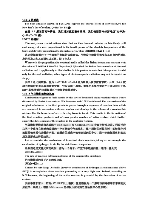
UNIT2热对流For both situation shown in Fig.1.2,we express the overall effect of convection,we use New-ton”s law of cooling: Q=Ha(Tw-T8横)在图 1.2所示的两种情况,我们对对流的整体效果,我们使用的冷却新吨级“定律为: Q=Ha(Tw-T8横)UNIT3热辐射Thermodynamic considerations show that an idea thermal radiator ,or blackbody ,will emit energy at a rate proportional to the fourth power of the absolute temperature of the body and directly proportional to its surface area. Thus q(emitted)=σAT4 (1-6)热力学规律揭示出一个理想的热辐射体或黑体,所散发出能量的速度与其自身的绝对温度的四次方和其表面积成正比。
即(公式)Where σ is the proportionality constant and is called the Stefan-Boltzmann constant with the value of 5.669*10-8 W/m2k4. Equation(1-6)is called the Stefan-Boltzmann law of thermal radiation, and it applies only to blackbodies. It is important to note that this equation is valid only for thermal radiation; other types of electromagnetic radiation may not be treated so simply.其中σ是比例常数,值为5.669*10-8 W/m2k4称为斯蒂凡玻尔兹曼常数。
最新热能与动力工程专业英语(整理版)
热能与动力工程Thermal Energy and Power Engineering材料与能源学院:Institute of Materials and Energy空调制冷:refrigeration and air conditioning热传导:thermol conduction学生毕业后能胜任现代火力发电厂,制冷与低温工程及相关的热能与动力工程专业的技术与管理工作,并能从事其它能源动力领域的专门技术工作.The graduates may find employment of technology and management in the fields of the Thermal Energy &Power Engineering (TEPE) and its relevance, such as modern power plant or the Refrigeration and Cryogenics Engineering (RCE), the graduates may also engaged in the special technique in the fields related to TEPE.现代空气动力学、流体力学、热力学、水力学以及航空航天工程、水利水电工程、热能工程、流体机械工程都提出了一系列复杂流动问题,其中包括高速流、低速流、管道流、燃烧流、冲击流、振荡流、涡流、湍流、旋转流、多相流等等A series of complicated flow problems have been posed in modern fluid mechanics, aero dynamics, thermodynamics, and aeronautical and aerospace engineering, water conservancy and hydropower engineering, heat energy engineering, fluid machinery engineering, and so on, and they cover high-speed flow, low-speed flow, eddy flow, turbulent flow, burning flow, impact flow, oscillating flow, backflow, and two-phase flow, etc.In the thermal engineering, the studied objects normally are isolated from one another and then we try to analysis the change and interaction, the studied objects isolated is named thermodynamic system.在热力工程中,通常将研究对象分离出来再分析其变化及(与外界)的相互作用,该对象即热力系统。
热能与动力工程专业英语
Chapter 1 Introduction to Thermal Science第一章热科学基础Acoustic flow meter 声波流量计Corrugated fin 波状散热片Adiabatic []绝热的Cross product 矢量积Aerodynamics 空气动力学Denominator 分母Affiliation 联系Developed flow 充分发展流Airfoil 机翼,螺旋桨Diffusion 扩散Alternative 替代燃料Doppler effect 多普勒效应Anemometer 风速计Double-pipe heat exchanger 套管式换热器Angular speed 角速度Dry saturated vapor 干饱和蒸汽Area density 表面密度Electrode 电极Baffle 挡板Electrolyte 电解,电解液Bifurcation 分形Electrostatic 静电的Blackbody 黑体Emissivity 发射率Blade 浆叶,叶片Equilibrium 平衡Boiler 锅炉Fluid mechanics 流体力学Boundary layer 边界层Forced convection 强制对流Carnot Cycle 卡诺循环Free convection 自然对流Cartesian coordinates 笛卡尔坐标系Friction loss 摩擦损失Celsius Degree 摄氏度Glass ceramic 微晶玻璃,玻璃陶瓷Heat engine 热机Compact heat exchanger 紧凑式换热器Composition 成分,合成物Heat pump 热泵Compressed liquid 压缩液体Hydrofoil 水翼Compressibility 可压缩性,压缩率Hypersonic speed 高超音速Condensation 凝结Infinitesimal 无穷小的Condenser 冷凝器Inflating/deflating 充气/压缩Conduction 导热Internal combustion engine 内燃机Control volume 控制体Isentropic 等熵的Convection 对流Isobaric 等压的Coriolis-accelaration flowmeter 科Isolated system 孤立体系的氏加速流量计Isometric 等容的Rough-wall tube 粗糙管Isothermal 等温的Saturation 饱和Kinematic viscosity 运动黏度Shear stress 剪切力、切应力Laminar 层流Shell-and-tube heat exchanger管壳式换热器Manuscript 手稿,原稿Specific volume 比容Moisture 湿度,水分Steady 稳态的,定常的Molecule (化学)分子Stifling engine 斯特林机Molten polymer 熔融聚合物Strain rate 变形速度,应变率Muti-disciplinary 多学科的Streamline 流线Newtonian Fluid 牛顿流体Strut 支撑,支柱Nominal temperature gradient 法向Subcooled liquid过冷液体温度梯度Numerator (数学)分子Superheated vapor 过热蒸汽Parallel flow 平行流动,并流Surrounding 环境,外界Pathline迹线Thermal conductivity 热传导率Phase change 相变Thermal efficiency 热效率Plane flow 平面流,二元流Thermodynamics 热力学Torsional 扭力的,扭转的Plate and flame heat exchanger板式换热器Polymer solution 胶浆Trailing edge 机翼后缘、尾缘Proof 校样Transmitter 传送装置、发送器Propeller 螺旋桨,推进器Turbine meter 涡轮流量计Pump泵Turbulent 湍流的Qulity 干度Ultrosonic 超声波的Qusi-equilibrium 准平衡、准静态Uniform flow 均匀刘Radiation 辐射Vacuum 真空Rankin Cycle 朗肯循环View factor 角系数Regenerative heat exchangerViscous 黏性的蓄热/再生式换热器Reservoir 水库,蓄水池Cortex shedding 漩涡脱落Reversible 可逆的Water faucet 水龙头,水嘴Rotameter 转子流量计Bi Biot number 比澳数NPSH 汽蚀余量CFD 计算流体力学NTU 传热单元数CHF 临界热流量Nu 努谢尔特数COP 制冷系数PE 势能Eu 欧拉数Pr 普朗特数Fo 富立叶数Ra 瑞利数Fr 弗劳德数Re 雷诺数Gr 格拉晓夫数Sc 施密特数KE 动能St 斯坦顿数,斯特劳哈数LMTD对数平均温差We 韦伯数1.1Fundamental of Engineering Thermodynamics1.1工程热力学基础Thermodynamics is a science in which the storage, transformation and transfer of energy are studied. Energy is stored as internal energy (associated with temperature), kinetic energy (du to motion), potential energy (due to elevation) and chemical energy (due to chemical composition); it is transformed from one of these forms to another; and it is transferred across a boundary as either heat or work.热力学是一门研究能量储存、转换及传递的科学。
热能毕业设计外文文献及翻译
用于分析在直燃式步进式加热炉板坯瞬态加热的传热模型摘要一个可以预测板坯表面温度分布和热流情况的数学传热模型已开发出来了,主要是通过充分考虑在炉膛内的板坯的热辐射和瞬态热传导方程来实现的。
该炉型是参照散热介质在空间中的变恒温过程和恒定的吸收系数来设计的。
钢坯由步进梁从一个固定梁移动到下一个固定梁上,是以通过加热炉预热段.加热段和均热段为钢坯热传导方程的边界条件的加热炉模型。
辐射热通量的计算是通过采用有限体积法,在炉子的内部,以炉墙.炉顶.炉底构成的充满烟气的环境里,作为板坯的瞬态传导方程的边界条件来进行计算的。
板坯的传热特性和温度特性是通过调查可以改变板坯吸收系数和发射率的参数来确定的。
比较多次的实践工作表明,目前用于预测板坯在加热炉中的传热过程和热流量的状况示范工程得到了很好的效果。
关键词:加热炉;钢坯加热;辐射传热;瞬态热传导;有限体积法1 导言在过去数十年以来,炉子进入降低能源消耗和污染物排放量的阶段,而分析钢坯瞬态热特性,在加热炉工程应用上已吸引了相当多注意。
此外,限定板坯在炉子内有均匀的温度分布才能出炉的重要性大大增加了,只有准确、快速的预测炉内板坯的温度,才能为以后的轧制过程提供比较好的原料,因为这决定了钢铁产品质量的高低。
在本质上,在炉膛内的整个燃烧过程和由此产生的热气流同时影响传热.对流和热辐射过程。
然而,复杂的炉子内部的三维结构包括固定梁和步行梁打滑问题使的难以在经济上做出准确的分析。
因此,模型和方法对于预测炉子内部燃烧特性和传热过程中存在着很高的要求。
尤其是,准确预测热辐射量是最重要的,因为热辐射传热超过流过板坯表面总热流的90%。
现在没有一个单一的辐射模型就能够解决所有在工程应用中遇到的情况,所以应选择一个合适的途径为自己的侧重点。
为了预测通过板坯表面上的辐射热通量,从而准确计算出炉子内板坯的温度分布,其解决方法是板坯必须是做连续运动,无灰的燃烧烟气作为该炉辐射气体,以及复杂的炉壁几何结构包括弯曲的板坯和防滑管道堵塞的影响,还有就是一定量的计算。
热能与动力工程专业英语
i.e. it is in steady-state.Often we will consider process that change “slowly”-termed quasi-equilibrium or quasi-static process.A process is quasi-equilibrium if the time rate of change of the process is slow relative to the time it takes for the system to reach thermodynamic equilibrium.It is necessary that a system be quasi-equilibrium before applying many of the thermodynamics relations to that system.热力学第一二定律:In simplest terms,the law of thermodynamics dictate the specific for the movement of heat and work.Basically,the First Law of Thermodynamic is a statement of the conservation of energy-the Second Law is a statement about the direction of that conservation-and the Tired Law is a statement about reaching absolute Zero.The first law of thermodynamic is a statement of the principle of conservation of energy.It can also be considered as defining a property,the internal energy.The Second law of Thermodynamic states that in all energy exchanges,if no energy enters or leaves the system,the potential energy of the state will always be less than that of the initial states.This is also commonly referred to as entropy.举例说明热力学定律应用:a cup of hot coffee left on a table eventually cools,but a cup of cool coffee in the same room never gets hot by itself.The high-temperature energy of the coffee is degraded(transformed into a less useful form at a lower temperature)once it is transferred to the surrounding air.An ordinary house is,in some respects,an exhibition hall filled with womders of thermodynamics.Many ordinary household utensils and applicances are designed,in whole or in part,by using the principles of thermodynamics.Some examples include the electric or gas range,the heating and air-condition systems,the refrigerator,the humidifier,the pressure cooker,the water heater,the iron,and even the computer,and the TV.On a large scale,thermodynamics plays a major part in the design and analysis of automotive engines,rockets,jet engine,and conventional or nuclear power plans,solar collectors,and the design of vehicle form ordinary cars to airplanes.绝热系统:isolated systems:not exchangeing heat,matter or work with their environment.开口系统:exchanging energy (heat and work )and matter with their environment .闭口系统:exchangeing energy (heat and work )but not matter with their environment .孤立系统:rigid boundary :not allowing exchange of work .辐射换热:The mechanism in this case is electromagnetic radiation .We shall limit our discussion to electromagnetic radiation which is propagated as a result of a temperature difference ;this is called thermal radiation .对流传热:when a fluid at rest or in motion is in contact with a surface at a temperature different from the plate ,energy flows in the direction of the lower temperature as required by the principle of thermodynamics .we say that heat is convected away ,and we call the process convection heat transfer .对流传热的方式:There are two convection modes :forced convection and natural convection .If a heated plate were exposed to ambient room air without an external source of motion ,a movement of the air would be experienced as a result of the density gradients near the plate .We call this natural ,or free ,convection as opposed to forced convection ,which is experienced in the case of the fan blowing air over a plate .传热学:Heat transfer is the science that seeks to predict the energy transfer that may take place between material bodies as a result of a temperature difference .传热学和热力学的区别:Thermodynamics teaches that this energy transfer is defined as heat .The science of heat transfer seeks not merely to explain how heat energy may be transferred ,but also to predict the rate at which the exchange will take place under certain specified conditions .The fact that a heat -transfer rate is the desired objective of an analysis points out the difference between heat transfer and thermodynamics .Thermodynamics deals with systems in equilibrium ;it may be used to predict the amount of energy required to change a system from one equilibrium state to another ;it may not be used to predict how fast a change will take place since the system is not in equilibrium during the process .Heat transfer supplements the first and second principles of thermodynamics by providing additional experimental rules which may be used to establish energy -transfer rates .As in the science of thermodynamics ,the experimental rules used as a basis of the subject of heat transfer are rather simple and easily expanded to encompass a variety of practical situations .影响辐射传热的因素:To take account of the “gray” nature of such surface we introduce another factor into热能与动力工程thermal energy and power engineering能量转化energy-transfer比例常数proportionality constant比例系数proportionality factor活性中心active center对流传热convection heat transfer电磁辐射electromagnetic radiation角系数view factor准静态过程quasi-static process准平衡quasi-equilibrium静态平衡static equilibrium强度参数intensive property广延参数extensive property燃烧机理combustion mechanism平均分子运动average molecular motion 热反应堆thermal reactor热力学性质thermodynamic property摩尔热容molar heat capacity动能kinetic energy压缩因子compressibility factor温度传感器temperature sensor测量电路measurement circuit电压输出voltage output静电荷electrostatic charge励磁电源excitation power内能internal energy能量原理energy principle能量平衡energy balance能量守恒conservation of energy剪切应力shear force/stress角速度angular velocity速度梯度velocity gradient温度梯度temperature gradient一维one-dimensional机械能mechanical energy内能internal energy动能kinetic energy势能potential energy凝固/硬化take a set流体动力学fluid dynamic hydrodynamics 蒸汽发生系统steam generating system辅助设备auxiliary equipment空煤比the air-coal ratio质量作用定律the law of mass action阿伦尼乌斯定律arrhennius law活化分子active molecule活化分子碎片active molecule fragments 活化能activation energy 自由价free valency支链反应定律the law of branched chain reactions 化学反应方程式stoichiometric equation活化中心active centres能级energy levels甲烷methane ch4压缩机compressor冷凝器condenser膨胀阀expansion valve可逆reversible绝热adiabatic等熵isentropic余隙容积clearance volume比容specific volume压力损失pressure loss溶液给水温度liquid feed temperature体积流速the volume flow rate液压头liquid head成比例的proportional成反比例的inversely proportional热力学定律principles of thermodynamics平衡温度equilibrium temperature相变phase change导热性thermal conductivity传热系数heat transfer coefficient强制对流forced convection自然对流natural convection外表面external surface焓enthalpy熵entropy对流传热convection heat transfer牛顿冷却公式Newton law of cooling流体物性properties of the liquid质量流量比mass flow ratio电磁辐射能electromagnetic energy热辐射thermal radiation净辐射量net radiation流体力学fluid mechanics热力学性质thermodynamic property牛顿粘性定律Newton law of vosicosity温熵图temperature-entropy diagram回转式发动机rotary engine汽轮机steam turbine光化学烟雾photochemical smog核电站nuclear power plant流化床燃烧fluildized bed combustion余热锅炉a heat recovery builer表面积surface areai.e. it is in steady-state.Often we will consider process that change “slowly”-termed quasi-equilibrium or quasi-static process.A process is quasi-equilibrium if the time rate of change of the process is slow relative to the time it takes for the system to reach thermodynamic equilibrium.It is necessary that a system be quasi-equilibrium before applying many of the thermodynamics relations to that system.热力学第一二定律:In simplest terms,the law of thermodynamics dictate the specific for the movement of heat and work.Basically,the First Law of Thermodynamic is a statement of the conservation of energy-the Second Law is a statement about the direction of that conservation-and the Tired Law is a statement about reaching absolute Zero.The first law of thermodynamic is a statement of the principle of conservation of energy.It can also be considered as defining a property,the internal energy.The Second law of Thermodynamic states that in all energy exchanges,if no energy enters or leaves the system,the potential energy of the state will always be less than that of the initial states.This is also commonly referred to as entropy.举例说明热力学定律应用:a cup of hot coffee left on a table eventually cools,but a cup of cool coffee in the same room never gets hot by itself.The high-temperature energy of the coffee is degraded(transformed into a less useful form at a lower temperature)once it is transferred to the surrounding air.An ordinary house is,in some respects,an exhibition hall filled with womders of thermodynamics.Many ordinary household utensils and applicances are designed,in whole or in part,by using the principles of thermodynamics.Some examples include the electric or gas range,the heating and air-condition systems,the refrigerator,the humidifier,the pressure cooker,the water heater,the iron,and even the computer,and the TV.On a large scale,thermodynamics plays a major part in the design and analysis of automotive engines,rockets,jet engine,and conventional or nuclear power plans,solar collectors,and the design of vehicle form ordinary cars to airplanes.绝热系统:isolated systems:not exchangeing heat,matter or work with their environment.开口系统:exchanging energy (heat and work )and matter with their environment .闭口系统:exchangeing energy (heat and work )but not matter with their environment .孤立系统:rigid boundary :not allowing exchange of work .辐射换热:The mechanism in this case is electromagnetic radiation .We shall limit our discussion to electromagnetic radiation which is propagated as a result of a temperature difference ;this is called thermal radiation .对流传热:when a fluid at rest or in motion is in contact with a surface at a temperature different from the plate ,energy flows in the direction of the lower temperature as required by the principle of thermodynamics .we say that heat is convected away ,and we call the process convection heat transfer .对流传热的方式:There are two convection modes :forced convection and natural convection .If a heated plate were exposed to ambient room air without an external source of motion ,a movement of the air would be experienced as a result of the density gradients near the plate .We call this natural ,or free ,convection as opposed to forced convection ,which is experienced in the case of the fan blowing air over a plate .传热学:Heat transfer is the science that seeks to predict the energy transfer that may take place between material bodies as a result of a temperature difference .传热学和热力学的区别:Thermodynamics teaches that this energy transfer is defined as heat .The science of heat transfer seeks not merely to explain how heat energy may be transferred ,but also to predict the rate at which the exchange will take place under certain specified conditions .The fact that a heat -transfer rate is the desired objective of an analysis points out the difference between heat transfer and thermodynamics .Thermodynamics deals with systems in equilibrium ;it may be used to predict the amount of energy required to change a system from one equilibrium state to another ;it may not be used to predict how fast a change will take place since the system is not in equilibrium during the process .Heat transfer supplements the first and second principles of thermodynamics by providing additional experimental rules which may be used to establish energy -transfer rates .As in the science of thermodynamics ,the experimental rules used as a basis of the subject of heat transfer are rather simple and easily expanded to encompass a variety of practical situations .影响辐射传热的因素:To take account of the “gray” nature of such surface we introduce another factor into热能与动力工程thermal energy and power engineering能量转化energy-transfer比例常数proportionality constant比例系数proportionality factor活性中心active center对流传热convection heat transfer电磁辐射electromagnetic radiation角系数view factor准静态过程quasi-static process准平衡quasi-equilibrium静态平衡static equilibrium强度参数intensive property广延参数extensive property燃烧机理combustion mechanism平均分子运动average molecular motion 热反应堆thermal reactor热力学性质thermodynamic property摩尔热容molar heat capacity动能kinetic energy压缩因子compressibility factor温度传感器temperature sensor测量电路measurement circuit电压输出voltage output静电荷electrostatic charge励磁电源excitation power内能internal energy能量原理energy principle能量平衡energy balance能量守恒conservation of energy剪切应力shear force/stress角速度angular velocity速度梯度velocity gradient温度梯度temperature gradient一维one-dimensional机械能mechanical energy内能internal energy动能kinetic energy势能potential energy凝固/硬化take a set流体动力学fluid dynamic hydrodynamics 蒸汽发生系统steam generating system辅助设备auxiliary equipment空煤比the air-coal ratio质量作用定律the law of mass action阿伦尼乌斯定律arrhennius law活化分子active molecule活化分子碎片active molecule fragments 活化能activation energy自由价free valency 支链反应定律the law of branched chain reactions 化学反应方程式stoichiometric equation活化中心active centres能级energy levels甲烷methane ch4压缩机compressor冷凝器condenser膨胀阀expansion valve可逆reversible绝热adiabatic等熵isentropic余隙容积clearance volume比容specific volume压力损失pressure loss溶液给水温度liquid feed temperature体积流速the volume flow rate液压头liquid head成比例的proportional成反比例的inversely proportional热力学定律principles of thermodynamics平衡温度equilibrium temperature相变phase change导热性thermal conductivity传热系数heat transfer coefficient强制对流forced convection自然对流natural convection外表面external surface焓enthalpy熵entropy对流传热convection heat transfer牛顿冷却公式Newton law of cooling流体物性properties of the liquid质量流量比mass flow ratio电磁辐射能electromagnetic energy热辐射thermal radiation净辐射量net radiation流体力学fluid mechanics热力学性质thermodynamic property牛顿粘性定律Newton law of vosicosity温熵图temperature-entropy diagram回转式发动机rotary engine汽轮机steam turbine光化学烟雾photochemical smog核电站nuclear power plant流化床燃烧fluildized bed combustion余热锅炉a heat recovery builer表面积surface area。
- 1、下载文档前请自行甄别文档内容的完整性,平台不提供额外的编辑、内容补充、找答案等附加服务。
- 2、"仅部分预览"的文档,不可在线预览部分如存在完整性等问题,可反馈申请退款(可完整预览的文档不适用该条件!)。
- 3、如文档侵犯您的权益,请联系客服反馈,我们会尽快为您处理(人工客服工作时间:9:00-18:30)。
Enhancement of Forced Convection Heat TransferRongzhen YouClass 1202 of Power EngineeringIn my College Students Innovative Project, we are supposed to adopt some methods to enhance the forced convection heat transfer on the plain surface. Although we have taken several technical methods into consideration, most of them are too difficult for us to apply in our project. Therefore, I would like to make an introduction to these methods here.Firstly, machining some grooves or dimples on the plain plates is one of important methods to enhance the convection heat transfer. The grooves or dimples can change the flow field of the fluid near the surface, for which the fluid would be turbulent than before. In this way, the Nusselt number of the near surface fluid would be raised, and than the convection heat-transfer coefficient would increase. This method can enhance the convection heat transfer on the plain plate to some extent, but it’s still ineffective for the reason that the improvement of heat-transfer coefficient of the fluid in the near wall region can not enhance the heat-transfer of the mainstream.Secondly, some researchers come up with an idea that using spiral fine ribs (SFRs) in plate channel to enhance the convection heat transfer. They equally placed the SFRs in the channel, which can form a packing layer resembling a kind of quasi-porous media with large porosity and can produce efficient disturbance both to the boundary layer and the mainstream. The operation principle of SFRs is that the multi-longitudinal vortices induced by SFRs can significantly increase the tangential velocity components in the cross section, which is helpful to promote the micro-fluctuation in the fluid. What’s more, the transport action caused by the longitudinal vortices can improve the mass exchange between the boundary layer and the mainstream. These two factors can not only speed up the heat migration from the channel walls, but also enhance the heat diffusion in the mainstream. This improves the temperature distribution uniformity in channel.Thirdly, the most efficient way to enhance the convection heat transfer is installing fins on the plain plate. Base on this thought, some researchers have fabricated many different types of fins, such as columned pin fins, conical pin fins, elliptical pin fins, cross-cut pin fins and longitudinal vortex generator arrays (LVG). Nowadays, fins with geometric shape pins have been commonly used to in the engineering. As for the vortex generator, it can disturb the flow field by the vortex and generate vortex after the generator, which can break the boundary lay on the surface and transfer the heat into mainstream quickly. Nowadays, many researchers have proved that the LVG effect is much better than the straight fins within a certain limit of Reynolds number, as well as that the multi rows LVG can improve the whole heat transfer effect.The methods mentioned above sounds pretty advanced, but it’s quiet difficult for us, regular college students, to apply these methods in our project. Because we couldn’t analysis the complex flow field in these special structure, unless we use the FLUENT software to build up their mathematic model. As the advanced usage of FLUENT is out of our ability, we have no choices but to install the straight fins on the heat transfer surface. Some researchers have found that the overall thermal resistance of straight fins is lower than other geometric pin fins, due to the combination effect of enhanced later conduction along the fins and the lower flow bypass characteristics. At last, our experiment also proved that the straight fin can meet the requirement of the enhancement of forced convection heat transfer.References1. Christopher L. Chapman, and Seri Lee, Thermal Performance of an Elliptical Pin Fin Heat Sink, Silicon Graphics Computer Systems Mountainview, California, 940392. Pradeep Salapakkam, Ri Li, Mehmet Arik, Bill Gerstler, Augmenting Forced Convection Heat Transfer Coupled with an Aerodynamic Surface and a Synthetic Jet, One Research Circle, Niskayuna, NY 123093. Zhang Xiang, Research on Forced Convection Heat Transfer of Parallel Plate with Grooves, China Academic Journal Electronic Publishing House, TK 1234. Tang Yufeng, Research on Heat Transfer Enhancement Mechanism and Heat Transfer Characteristic of Spiral Fine Ribs in Plate Channel, China Academic Journal Electronic Publishing House, TK1245. K.W. Low, and C. Yap,The Enhanced Cooling of IC Chip Arrays On Printed Circuit Boards, Electronics Packaging Technology Conference, Singapore, 1192606. Gaowen Liu, Peng zhao, Zongwei zhang, Tao Liu, Transient Infrared Heat Transfer Measurements and Surface Flow Visualization on a Single Dimpled Wall, Journal of Propulsion Technology, Feb. 2009, V ol.30 No.11.。