永磁涡流制动器
Electromagnetic Eddy Current Brake(电磁涡流刹车)

DWS70电磁涡流刹车使用说明书上海申通石油机械厂一、性能及说明DWS70型涡流刹车作为钻深为7000米的海洋或陆地钻机的辅助刹车,既可与绞车成套供应,也可为矿场已经使用的钻机配套作为单独部件供应。
1、技术规范最大扭矩110000N.m钻井深度(用41/2"钻杆) 7000m作用原理感应涡流制动线圈个数 4每个线圈额定电阻(20°C时) 10.722Ω线圈绝缘等级H级励磁功率23KW励磁电流(四线圈并联时)84A需用冷却水量 560L/min最大出水温度(当进水温度42°C时)78°C重量 11000kg二、结构电磁涡流刹车由刹车主体、可控硅整流装置及司钻开关等三部分组成。
1、刹车主体它由两个基本部分组成,如图一所示。
其一为静止部分,称为定子;其二为转动部分,称为转子。
在定子与转子之间有一定的气隙,称为工作气隙,电磁涡流刹车的刹车主体采用外电枢结构的型式,也就是说,其转子在定子外面旋转。
刹车的定子由磁极和激磁线圈构成。
磁极是磁路的一部分,采用电工钢成,这种材料的导磁系数高,矫顽力小,以满足下钻时有用制动扭矩大,而起空吊卡时无用制动扭矩小的要求。
激磁线圈是刹车的电路部分,工作时通以直流电流,它固定于磁极上,与磁极组成一个整体成为定子。
刹车在运行时要产生大量的热量,因此激磁线圈采用了耐高温的电磁线与相应的绝缘材料,以保证线圈在高温下仍具有良好的绝缘性能。
图一 电磁涡流刹车结构示意图1. 端盖2. 转子3. 机座4. 定子5. 激磁线圈6.上呼吸器7.下呼吸器刹车的转子通过齿式离合器与绞车滚筒轴相联,由绞车滚筒驱动,与滚筒同速旋转。
转子既是磁路的一部分,又是电路的一部分,采用电工钢制成。
它和定子磁极、工作气隙构成刹车的完整磁路。
2.可控硅整流装置:它由整流变压器和可控硅半控桥式整流电路组成。
用以将钻机交流发电机或交流电网供给的交流电压变成可调直流电压,给激磁线圈通以可调直流电流。
涡流制动器工作原理
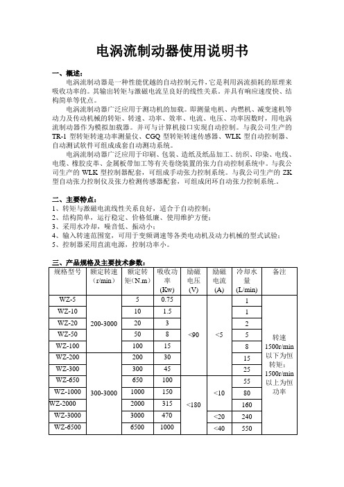
电涡流制动器使用说明书一、概述:电涡流制动器是一种性能优越的自动控制元件,它是利用涡流损耗的原理来吸收功率的。
其输出转矩与激磁电流呈良好的线性关系。
并具有响应速度快、结构简单等优点。
电涡流制动器广泛应用于测功机的加载。
即测量电机、内燃机、减变速机等动力及传动机械的转矩、转速、功率、效率、电流、电压、功率因数时,用电涡流制动器作为模拟加载器。
并可与计算机接口实现自动控制。
与我公司生产的TR-1型转矩转速功率测量仪、CGQ型转矩转速传感器、WLK型自动控制器、自动测试软件可组成成套自动测功系统。
电涡流制动器广泛应用于印刷、包装、造纸及纸品加工、纺织、印染、电线、电缆、橡胶皮革、金属板带加工等有关卷绕装置的张力自动控制系统中。
与我公司生产的WLK型控制器配套,可组成手动张力控制系统。
与我公司生产的ZK 型自动张力控制仪及张力检测传感器配套,可组成闭环自动张力控制系统.。
二、主要特点:1、转矩与激磁电流线性关系良好,适合于自动控制;2、结构简单,运行稳定、价格低廉、使用维护方便;3、采用水冷却,噪音低、振动小;4、输入转速范围宽,可用于变频调速等各类电动机及动力机械的型式试验;5、控制器采用直流电源,控制功率小。
四、特性曲线注:P0为最大冷却功率;n1为额定最低转速;n2为额定最高转速。
五、使用环境1、最高环境温度不超过40℃;2、海拔高度不超过2000m;3、当环境温度为20℃时,相对湿度不大于85%。
六、冷却水1、水质。
冷却水为自来水,一般工业用水、地下水、河水。
水中不含有直径1mm 以上的固体颗粒或其它杂物,其pH值为6-8,硬度为200ppm以下为宜,最大值为300ppm。
2、水压。
进水压力一般为不小于0.1Mpa,不大于0.3Mpa。
用户在使用本产品时应安装水压表和进水阀门,以方便监控和调节水量。
3、水量。
冷却水量见参数表,进水量的大小按测试功率的不同进行调节。
4、水温。
进水温度最高不超过30℃,出水温度约为50℃-60℃为宜,使用时可根据出水温度的高低调节水量。
列车涡流制动机理及制动力矩模型
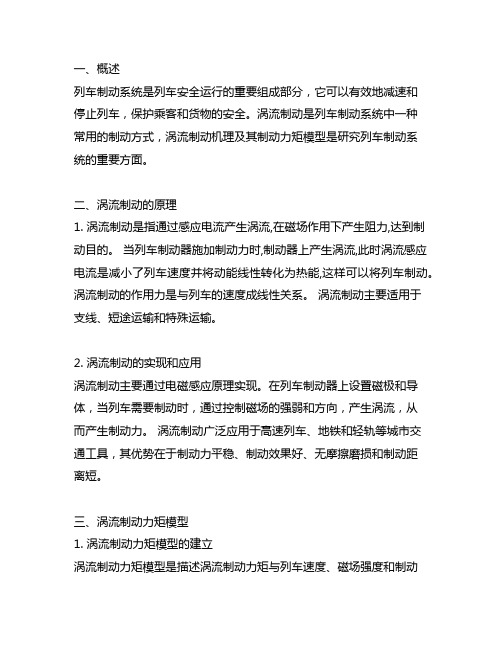
一、概述列车制动系统是列车安全运行的重要组成部分,它可以有效地减速和停止列车,保护乘客和货物的安全。
涡流制动是列车制动系统中一种常用的制动方式,涡流制动机理及其制动力矩模型是研究列车制动系统的重要方面。
二、涡流制动的原理1. 涡流制动是指通过感应电流产生涡流,在磁场作用下产生阻力,达到制动目的。
当列车制动器施加制动力时,制动器上产生涡流,此时涡流感应电流是减小了列车速度并将动能线性转化为热能,这样可以将列车制动。
涡流制动的作用力是与列车的速度成线性关系。
涡流制动主要适用于支线、短途运输和特殊运输。
2. 涡流制动的实现和应用涡流制动主要通过电磁感应原理实现。
在列车制动器上设置磁极和导体,当列车需要制动时,通过控制磁场的强弱和方向,产生涡流,从而产生制动力。
涡流制动广泛应用于高速列车、地铁和轻轨等城市交通工具,其优势在于制动力平稳、制动效果好、无摩擦磨损和制动距离短。
三、涡流制动力矩模型1. 涡流制动力矩模型的建立涡流制动力矩模型是描述涡流制动力矩与列车速度、磁场强度和制动器参数之间的关系。
一般而言,涡流制动力矩与列车速度成线性关系,与磁场强度和制动器参数有一定的相关性。
2. 涡流制动力矩模型的优化为了更准确地描述涡流制动力矩的特性,可以通过实验和理论分析,优化涡流制动力矩模型的参数,如磁场强度、制动器结构和材料等,以提高制动效果和降低能耗。
四、涡流制动机理及制动力矩模型的应用1. 在列车制动系统中的应用涡流制动机理及制动力矩模型广泛应用于列车制动系统中,通过对涡流制动的机理和力矩模型的深入研究,可以优化列车制动系统的设计和参数设置,提高制动效果和安全性。
2. 在城市轨道交通中的应用涡流制动技术在城市轨道交通中得到了广泛应用,通过对涡流制动力矩模型的研究和改进,可以提高城市轨道交通的运行效率和安全性。
五、结论通过对涡流制动的机理及其力矩模型的研究,可以更好地理解涡流制动的工作原理,优化涡流制动系统的设计和参数设置,提高列车和城市轨道交通的运行效率和安全性。
电磁飞机弹射系统永磁涡流制动装置的分析与设计
.
… …
磊 { ≥… … … … … … … … … … … … … … … … … … … … … … 一 . 二… … … … . . 一 。 . : … - - -: : … : ….
触持电棚 2 0 1 3 年 第 4 1 卷 第 8 期
电磁 飞 机 弹 射 系统 永磁 涡 流 制 动 装 置 的分 析 与 设 计
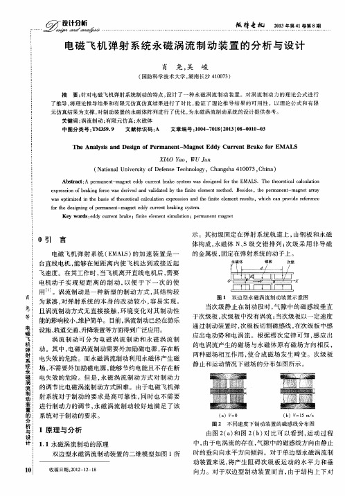
Ab s t r a c t : A p e r ma n e n t - ma g n e t e d d y c u r r e n t b r a k e s y s t e m w a s d e s i g n e d f o r t h e EMA L S .T h e t h e o r e t i c a l c a l c u l a t i o n e x p r e s s i o n o f b r a k i n g f o r c e w a s d e r i v e d a n d v a l i d a t e d b y t h e i f n i t e e l e me n t me t h o d .Be s i d e s ,t h e p e ma r n e n t — ma g n e t a ra y wa s o p t i mi z e d i n t h e b a s i s o f t h e o r e t i c a l c a l c u l a t i o n e x p r e s s i o n a n d t h e i f n i t e e l e me n t r e s u l t s ,w h i c h c a n p r o v i d e r e f e r e n c e or f t h e d e s i g n i n g o f p e r ma n e n t - ma g n e t e d d y c u re n t b r a k i n g s y s t e m.
有轨电车涡流制动器结构设计与仿真分析
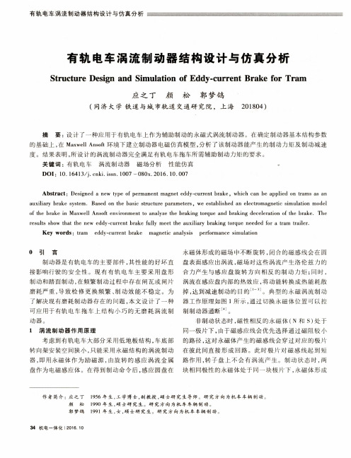
永磁 体 形 成 盘 作为 电磁感 应体 。在得 到 制 动命令 后 , 感 应 圆盘 在 块 相 同极性 的永磁 体处 于 同一 块极 片 下,
作 者 简介 :应 之 丁 l 9 5 6年 生 , 工学博士 , 副教 授 , 硕 士 研 究 生 导 师 。研 究 方 向 为 机 车 车 辆 制 动 。
有轨 电车 涡流 制动器 结构 设计 与仿 真分析
有 轨 电 车 涡 流 制 动 器 结 构 设 计 与 仿 真 分 析
S t r u c t u r e De s i g n a n d S i mu l a t i o n o f Ed d y ・ c u r r e n t Br a k e f o r Tr a m
制 动和踏 面制 动 , 在 频繁 制动 过 程 中存在 闸瓦或 闸片 涡 流在 感应 盘 内部的 热效应 , 将 动 能转 换 成热 能 耗 散
磨耗 严重 , 导致检修更换频繁 、 制 动 效 能 不 稳 定 。为 掉 , 达 到减速 制动 的 目的
。典型 的 永磁 涡 流 制 动
了解 决现 有磨 耗制 动器 存在 的 问题 , 本文 设 计 了一 种 器 工作 原理 如图 1 所示, 通 过 切换 永磁 体 位置 可 以 控 可应 用于 有轨 电车 拖 车 上 结 构 小巧 的 无 磨 耗 涡 流 制 制制动 器通 断 。
涡流制动器工作原理
涡流制动器工作原理
涡流制动器是一种常见的制动装置,它通过涡流的产生来实现制动效果。
在涡
流制动器中,通过外加电流在导体内产生涡流,涡流受到磁场的阻碍而产生制动力,从而实现制动的效果。
接下来,我们将详细介绍涡流制动器的工作原理。
首先,涡流制动器的核心部件是导体。
当导体处于磁场中时,外加电流会在导
体内部产生环流,这种环流就是涡流。
涡流产生后,会受到磁场的作用而产生阻力,这个阻力就是制动力的来源。
其次,涡流制动器的工作原理是利用涡流和磁场之间的相互作用。
当导体内产
生涡流时,涡流会受到磁场的阻碍而产生制动力。
这种制动力可以用来减速或停止运动物体的运动。
涡流制动器的工作原理可以简单地总结为,外加电流在导体内产生涡流,涡流
受到磁场的阻碍而产生制动力。
这种制动力可以实现对运动物体的制动效果。
总的来说,涡流制动器的工作原理是利用涡流和磁场之间的相互作用来产生制
动力。
通过外加电流在导体内产生涡流,涡流受到磁场的阻碍而产生制动力,从而实现对运动物体的制动效果。
在实际应用中,涡流制动器常常用于需要快速减速或停止的场合,如列车制动、工业生产线的制动等。
其工作原理简单而有效,使得涡流制动器成为制动领域中的重要装置之一。
电磁涡流制动工作原理
电磁涡流制动工作原理嗨,朋友!今天咱们来聊聊一个超级酷的东西——电磁涡流制动。
你有没有想过,当一辆高速行驶的列车要停下来,或者一个大型的旋转机器要迅速减速,靠的是什么神奇的力量呢?这其中就有电磁涡流制动的功劳呢!先来说说什么是涡流吧。
想象一下,你在一个平静的湖面上,突然丢进去一块大石头。
这时候,水面就会泛起一圈圈的涟漪,这些涟漪就像是一种水流的漩涡。
在金属里面呢,当有变化的磁场穿过的时候,也会产生类似漩涡的电流,这就是涡流啦。
这个涡流可不像湖面上的涟漪那么温柔无害哦,它有着特殊的作用呢。
那电磁涡流制动是怎么利用这个涡流来工作的呢?咱们来打个比方吧。
就好比你在一个满是旋转木马的游乐场里。
每个木马就像是一个小小的金属块。
现在呢,来了一个超级大的磁铁,这个磁铁就像一个严厉的管理员,它一靠近那些旋转的木马(金属块),就会在木马里面产生那种漩涡一样的电流,也就是涡流。
这时候,那些涡流就会像一个个小捣蛋鬼一样,它们在金属里面跑来跑去。
可是它们跑来跑去可不是瞎玩的,它们会消耗能量呢!就好像一群调皮的孩子在一个大房间里跑来跑去,跑来跑去的过程中把房间里的东西都弄得乱七八糟,消耗了房间里的能量。
这种能量的消耗会让旋转的东西速度慢下来。
比如说,在列车的制动系统里,列车的轮子或者特定的金属部件就像是那些旋转木马。
当电磁涡流制动系统启动的时候,强大的磁场作用在这些部件上,产生涡流,然后通过涡流消耗能量,列车就开始减速啦。
我有个朋友,他是在一个大型工厂里工作的。
有一次他跟我讲他们厂里那些大型的旋转机器。
他说啊,那些机器转起来可快了,就像龙卷风一样。
但是呢,要让它们停下来可不容易。
以前他们用的是传统的制动方法,总是有点不尽人意。
后来厂里引进了电磁涡流制动系统。
他一开始还很怀疑呢,就问我:“这玩意儿真能行?”我就给他解释了电磁涡流制动的原理,就像我给你解释的一样。
他似懂非懂的。
结果呢,当他们开始使用这个新的制动系统之后,他可惊讶了。
高速下的涡流制动:德国高速列车上安全、可靠和无磨损的制动器
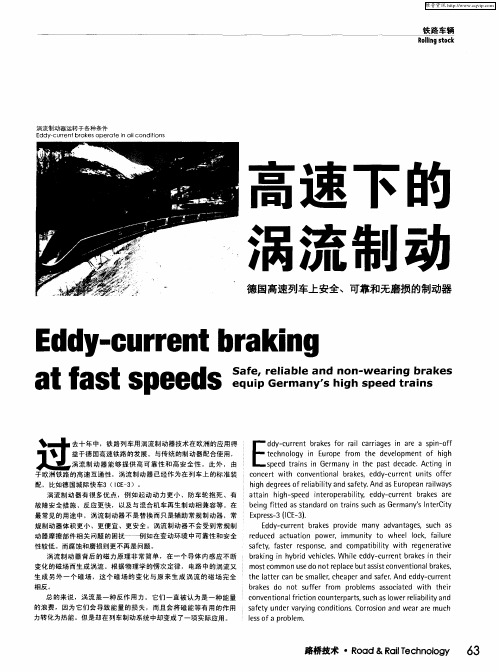
e u e a t a i p we .i o nt o y e l c . alr l Ue 动器摩 擦部件相关 问题 的困扰一一 例如在变 动环境 中可靠性和 安全 r d c d c u t n o r mmu i t wh e o k f i s f t .f s e r s o s .a d o a i i t wih e e e a i e a e y a t r e p n e n c mp t l y b i t r g n r t v 性 较 低 。而 腐 蚀 和 磨 损 则 更 不 再 是 问题 。
L. s e d t isi G r a y i t e p s e a e A t g i p e r n n e m n n h a td c d . c i n a n
c n e t wih o v n i n l r k s d y C e t U i 0 r o c r t c n e to a b a e .e d — U r n n t 仟e r s
配 , 比如德 国城 际 快 车3 ( C 一 ) 。 IE 3 涡 流 制 动 器 有 很 多 优 点 ,例 如 起 动 动 力 更 小 、 防 车 轮 抱 死 、 有
hg e e frl blya ds ft. da u o e nr i y ihd g e so i it n a ey An sE r p a al s r ea i wa
c n e to a r t n C U t r a t . u h a we l b l va d o v n i n l i i O n e p rs s c sl fc o o rr i i t n ea i
总 的 来 说 , 涡 流 是 一 种 反 作 用 力 。 它 们 一 直 被 认 为 是 一 种 能 量 的 浪 费 ,因 为 它们 会 导致 能 量 的 损 失 , 而且 会 将 磁 能 等 有 用 的 作 用
- 1、下载文档前请自行甄别文档内容的完整性,平台不提供额外的编辑、内容补充、找答案等附加服务。
- 2、"仅部分预览"的文档,不可在线预览部分如存在完整性等问题,可反馈申请退款(可完整预览的文档不适用该条件!)。
- 3、如文档侵犯您的权益,请联系客服反馈,我们会尽快为您处理(人工客服工作时间:9:00-18:30)。
Abstract
A new method of measuring reversible permeability is described. The method is not limited by the need to employ laminated specimens of material, since allowance is made for eddy-current effects within the specimen. Measurements were made on solid-bar specimens of two types of rail steel at a frequency of 5 kHz. The results cover biasing field strengths between 160 and 170kA/m.
Measurement of reversible permeability using solid (nonlaminated) specimens
R. Langman, Dip.Tech.(Elec.Eng.)
Indexing terms: Eddy currents, Permeability measurement, Steel
the ratio of the change of flux density to the change of field producing it, i.e. A.8//z0A//, is the incremental permeability ju,A . Bb and Hb are referred to as the biasing-induction and
Hale Waihona Puke List of principal symbols B = flux density, T H = magnetic field strength, A/m /JL0 = primary magnetic constant, H/m fxr = relative permeability /xA = incremental/reversible permeability PepA = apparent permeability R — search-coil radius, m rs = specimen radius, m a = single currenf-loop radius, m p = resistivity, Qm / = frequency, Hz o) = angular frequency, rad/s y/2\K = depth of pentration, m Introduction The requirement of measuring the permeability of solid specimens of steel arose from the development of an eddycurrent-type crack detector1 for use on steel rails. The detector consists of an( exciting coil carrying high-frequency current that induces eddy currents in the metal surface. The action of the induced currents can be likened to the secondary coil of a transformer, the exciting coil being the primary. The impedance of the primary depends on the magnitude of the eddy currents, which, in turn, depend on the metal in which they flow (and also on the proximity and dimensions of the exciting coil). When the metal surface is cracked or pitted, the flow of eddy current is obstructed, and this shows as a change of impedance of the excitation winding. It has been shown by Hammond2 that the distribution of eddy currents in a metal surface owing to a single flat-turn excitation coil is governed by a dimensionless factor represented by [jLcoa2lp. Study of this instrument therefore creates the need to measure [x for rail steel. Most methods of measurement rely on the use of laminated specimens to avoid eddycurrent effects. This approach cannot be adopted in this instance, since the metal under study is nonlaminated. A new method of measurement had to be devised. Permeability A ferromagnetic material has several permeabilities, and methods of measurement are determined by the particular permeability required. In this Section the definitions of permeability are discussed, so that the one relevant to the action of the crack detector can be found; this, in turn, determines the method of measurement. Fig. 1 shows the relationship between B and 7/for an initially unmagnetised specimen. The relative permeability [ir is defined as the ratio Bb/fjL0Hb. With increasing field strength, /xr increases to a maximum and then decreases. When the magnetic field in the specimen is kept constant and an additional field is alternated between limiting values,
1
Hb Fig. 1
H
B\H curve for ferromagnetic material
2
biasing-field strengths, respectively. It can be seen that JUA is less than fxr; but there is no simple relationship between the two quantities. The incremental permeability depends not only on Hb, but also on the amplitude of A/f; its value as A # tends to zero is called the reversible permeability JJLR. Note that, by definition, when Hb is zero, fxR — fjur (although, of course, it is not possible to measure \x.r at zero field strength). Sims3 discusses other factors influencing [MA; these include not only the amplitude of &.H but also its waveform. From the description of the crack detector, the yc in the expression \ioia1\p is the incremental permeability /u.^ with Hb=0. For the proposed crack-detection work, A// would be of the order of 200 A/m. Preliminary tests showed that /xA did not change measurably when AH was varied between 10 and 250A/m, and thus it is reasonable to assume that, at incrementalfieldstrengths of these amplitudes, the incremental and reversible permeabilities are equal. In the rest of this paper /xA will be used to denote reversible permeability. As stated, for normal operation of the crack detector, Hb would be zero, but it was deemed useful to measure values of /nA for a range of values of Hb, since this situation could occur in practical cases. Values of reversible permeability were then required at various biasing-field strengths for rail steel. With this in mind, methods of measurement are discussed in the following Section. Method of measurement of {xA The BjH curve of Fig. 1 is conveniently obtained using a laminated toroid of the specimen steel. A uniformly wound exciting winding produces a known field strength in the toroid; a search coil gives the change of flux on reversal of the magnetic field, and hence the flux density. Laminations are necessary to reduce currents that would 1887 3