DM74LS299WM中文资料
SN74LS122D中文资料
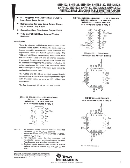
PRODUCTION DATA information is current as of publication date.Products conform to specifications per the terms of Texas Instrumentsstandard warranty. Production processing does not necessarily includetesting of all parameters.1POST OFFICE BOX 655303 • DALLAS, TEXAS 752652POST OFFICE BOX 655303 • DALLAS, TEXAS 752653 POST OFFICE BOX 655303 • DALLAS, TEXAS 752654POST OFFICE BOX 655303 • DALLAS, TEXAS 752655 POST OFFICE BOX 655303 • DALLAS, TEXAS 752656POST OFFICE BOX 655303 • DALLAS, TEXAS 752657 POST OFFICE BOX 655303 • DALLAS, TEXAS 752658POST OFFICE BOX 655303 • DALLAS, TEXAS 752659 POST OFFICE BOX 655303 • DALLAS, TEXAS 75265PACKAGING INFORMATIONOrderable Device Status (1)Package Type Package DrawingPins Package Qty Eco Plan (2)Lead/Ball FinishMSL Peak Temp (3)5962-7603901VEA ACTIVE CDIP J 161None Call TI Level-NC-NC-NC 5962-7603901VFAACTIVE CFP W 161None Call TI Level-NC-NC-NC 7603901EA ACTIVE CDIP J 161None Call TI Level-NC-NC-NC 7603901FA ACTIVE CFP W 161None Call TI Level-NC-NC-NC JM38510/01203BEA ACTIVE CDIP J 161None Call TI Level-NC-NC-NC JM38510/31401B2A ACTIVE LCCC FK 201None Call TI Level-NC-NC-NC JM38510/31401BEA ACTIVE CDIP J 161None Call TI Level-NC-NC-NC JM38510/31401BFAACTIVE CFP W 161None Call TI Level-NC-NC-NC SN54122J OBSOLETE CDIP J 14None Call TI Call TISN54123J ACTIVE CDIP J 161None Call TI Level-NC-NC-NC SN54LS123J ACTIVE CDIP J 161None Call TI Level-NC-NC-NC SN74122N OBSOLETE PDIP N 14None Call TI Call TISN74123N ACTIVE PDIP N 1625Pb-Free (RoHS)CU NIPDAU Level-NC-NC-NC SN74123N3OBSOLETE PDIP N 16None Call TI Call TISN74LS122D ACTIVE SOIC D 1450Pb-Free (RoHS)CU NIPDAU Level-2-260C-1YEAR/Level-1-235C-UNLIM SN74LS122DR ACTIVE SOIC D 142500Pb-Free (RoHS)CU NIPDAU Level-2-260C-1YEAR/Level-1-235C-UNLIM SN74LS122N ACTIVE PDIP N 1425Pb-Free (RoHS)CU NIPDAU Level-NC-NC-NC SN74LS122N3OBSOLETE PDIP N 14None Call TI Call TISN74LS122NSR ACTIVE SO NS 142000Pb-Free (RoHS)CU NIPDAU Level-2-260C-1YEAR/Level-1-235C-UNLIM SN74LS123D ACTIVE SOIC D 1640Pb-Free (RoHS)CU NIPDAU Level-2-260C-1YEAR/Level-1-235C-UNLIM SN74LS123DR ACTIVE SOIC D 162500Pb-Free (RoHS)CU NIPDAU Level-2-260C-1YEAR/Level-1-235C-UNLIM SN74LS123J OBSOLETE CDIP J 16None Call TI Call TISN74LS123N ACTIVE PDIP N 1625Pb-Free (RoHS)CU NIPDAU Level-NC-NC-NC SN74LS123N3OBSOLETE PDIP N 16None Call TI Call TISN74LS123NSR ACTIVE SO NS 162000Pb-Free (RoHS)CU NIPDAU Level-2-260C-1YEAR/Level-1-235C-UNLIM SNJ54122J OBSOLETE CDIP J 14None Call TI Call TISNJ54123J ACTIVE CDIP J 161None Call TI Level-NC-NC-NC SNJ54123W ACTIVE CFP W 161None Call TI Level-NC-NC-NC SNJ54LS123FK ACTIVE LCCC FK 201None Call TI Level-NC-NC-NC SNJ54LS123J ACTIVE CDIP J 161None Call TI Level-NC-NC-NC SNJ54LS123WACTIVECFPW161NoneCall TILevel-NC-NC-NC(1)The marketing status values are defined as follows:ACTIVE:Product device recommended for new designs.LIFEBUY:TI has announced that the device will be discontinued,and a lifetime-buy period is in effect.NRND:Not recommended for new designs.Device is in production to support existing customers,but TI does not recommend using this part in a new design.PREVIEW:Device has been announced but is not in production.Samples may or may not be available.PACKAGE OPTION ADDENDUM28-Feb-2005Addendum-Page 1元器件交易网OBSOLETE:TI has discontinued the production of the device.(2)Eco Plan -May not be currently available -please check /productcontent for the latest availability information and additional product content details.None:Not yet available Lead (Pb-Free).Pb-Free (RoHS):TI's terms "Lead-Free"or "Pb-Free"mean semiconductor products that are compatible with the current RoHS requirements for all 6substances,including the requirement that lead not exceed 0.1%by weight in homogeneous materials.Where designed to be soldered at high temperatures,TI Pb-Free products are suitable for use in specified lead-free processes.Green (RoHS &no Sb/Br):TI defines "Green"to mean "Pb-Free"and in addition,uses package materials that do not contain halogens,including bromine (Br)or antimony (Sb)above 0.1%of total product weight.(3)MSL,Peak Temp.--The Moisture Sensitivity Level rating according to the JEDECindustry standard classifications,and peak solder temperature.Important Information and Disclaimer:The information provided on this page represents TI's knowledge and belief as of the date that it is provided.TI bases its knowledge and belief on information provided by third parties,and makes no representation or warranty as to the accuracy of such information.Efforts are underway to better integrate information from third parties.TI has taken and continues to take reasonable steps to provide representative and accurate information but may not have conducted destructive testing or chemical analysis on incoming materials and chemicals.TI and TI suppliers consider certain information to be proprietary,and thus CAS numbers and other limited information may not be available for release.In no event shall TI's liability arising out of such information exceed the total purchase price of the TI part(s)at issue in this document sold by TI to Customer on an annualbasis.PACKAGE OPTION ADDENDUM 28-Feb-2005Addendum-Page 2IMPORTANT NOTICETexas Instruments Incorporated and its subsidiaries (TI) reserve the right to make corrections, modifications, enhancements, improvements, and other changes to its products and services at any time and to discontinue any product or service without notice. Customers should obtain the latest relevant information before placing orders and should verify that such information is current and complete. All products are sold subject to TI’s terms and conditions of sale supplied at the time of order acknowledgment.TI warrants performance of its hardware products to the specifications applicable at the time of sale in accordance with TI’s standard warranty. T esting and other quality control techniques are used to the extent TI deems necessary to support this warranty. Except where mandated by government requirements, testing of all parameters of each product is not necessarily performed.TI assumes no liability for applications assistance or customer product design. Customers are responsible for their products and applications using TI components. T o minimize the risks associated with customer products and applications, customers should provide adequate design and operating safeguards.TI does not warrant or represent that any license, either express or implied, is granted under any TI patent right, copyright, mask work right, or other TI intellectual property right relating to any combination, machine, or process in which TI products or services are used. Information published by TI regarding third-party products or services does not constitute a license from TI to use such products or services or a warranty or endorsement thereof. Use of such information may require a license from a third party under the patents or other intellectual property of the third party, or a license from TI under the patents or other intellectual property of TI.Reproduction of information in TI data books or data sheets is permissible only if reproduction is without alteration and is accompanied by all associated warranties, conditions, limitations, and notices. Reproduction of this information with alteration is an unfair and deceptive business practice. TI is not responsible or liable for such altered documentation.Resale of TI products or services with statements different from or beyond the parameters stated by TI for that product or service voids all express and any implied warranties for the associated TI product or service and is an unfair and deceptive business practice. TI is not responsible or liable for any such statements. Following are URLs where you can obtain information on other Texas Instruments products and application solutions:Products ApplicationsAmplifiers Audio /audioData Converters Automotive /automotiveDSP Broadband /broadbandInterface Digital Control /digitalcontrolLogic Military /militaryPower Mgmt Optical Networking /opticalnetwork Microcontrollers Security /securityTelephony /telephonyVideo & Imaging /videoWireless /wirelessMailing Address:Texas InstrumentsPost Office Box 655303 Dallas, Texas 75265Copyright 2005, Texas Instruments Incorporated。
74LS299
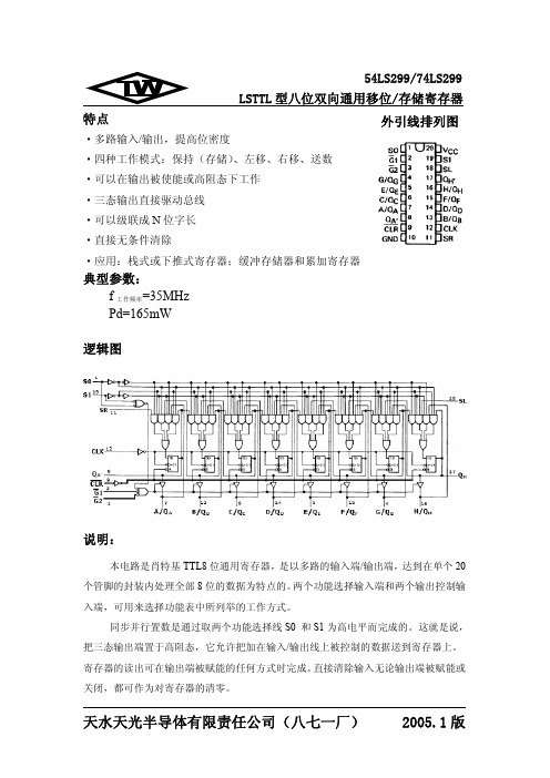
※ :数据包括两个串行输入 SL、SR 和八个输入/输出数据端。 ※
天水天光半导体有限责任公司(八七一厂)
2005.1 版
54LS299/74LS299 LSTTL 型八位双向通用移位/存储寄存器 电 性 能: (除特别说明外,均为全温度范围)
74Ⅱ 符号 VIK VOH 参数值 最小 典型 最大 输入钳位电压 Vcc=最小 II=-18mA -1.5 Vcc=最小 Q ~Q 2.4 A H VIL=最大 输出高电平电压 VIH=2V QA'、QH' 2.7 IOH=最大 Vcc=最小 Q ~Q 0.5 A H VIL=最大 输出低电平电压 VIH=2V QA'、QH' 0.5 IOL=最大 Vcc= 最 大 VIH=2.0V QA~QH 高关态输出电流 VIL= 最 大 Vo=2.7V Vcc= 最 大 VIH=2.0V QA~QH 低关态输出电流 VIL= 最 大 Vo=0.4V VI=7V 输入电流 S0、S1 (最大输入 A 到 H Vcc=最大 VI=5.5V 电压时) 其它 VI=7V S0、S1 Vcc= 最 大 A到H 输入高电平电流 VI=2.7V 其它 S0、S1 Vcc= 最 大 A到H 输入低电平电流 VI=0.4V 其它 Vcc=最大 VO=0V Vcc=最大 QA~QH
符号 参数名称 从(输入) 到(输出) 测试条件 (注) 时钟 CLK 清除 时钟 CLK 清除 QA 至 QH 输出控制
、 QA'或 QH'
最小 20
参数值 典型 35 22 26 27 17 26 26 13 19 10 10
最大 33 39 40 25 39 40 21 30 20 15
单位 MHz ns ns ns ns ns ns ns ns ns ns
最全Proteus元件库元件名称及中英对照,51单片机仿真软件Proreus

Proteus 元件库元件名称及中英对照AND 与门DPY_3-SEG 3 段LEDANTENNA 天线DPY_7-SEG 7 段LEDBATTERY 直流电源DPY_7-SEG_DP 7 段LED带小数BELL 铃钟点BVC 同轴电缆接插件ELECTRO 电解电容BRIDEG 1 整流桥二极管FUSE 熔断器BRIDEG 2 整流桥集成块INDUCTOR 电感BUFFER 缓冲器INDUCTOR IRON 带铁芯电感BUZZER 蜂鸣器INDUCTOR3 可调电感CAP 电容JFET N N 沟道场效应管CAPACITOR 电容JFET P P 沟道场效应管CAPACITOR POL 有极性电容LAMP 灯泡CAPVAR 可调电容LAMP NEDN 起辉器CIRCUIT BREAKER 熔断丝LED 发光二极管COAX 同轴电缆METER 仪表CON 插口MICROPHONE 麦克风CRYSTAL 晶体整荡器MOSFET MOS 管DB 并行插口MOTOR AC 交流电机DIODE 二极管MOTOR SERVO 伺服电机DIODE SCHOTTKY 稳压二极管NAND 与非门DIODE VARACTOR 变容二极管NOR或非门NOT 非门SW 开关NPN NPN 三极管SW-DPDY 双刀双掷开关NPN-PHOTO 感光三极管SW-SPST 单刀单掷开关OPAMP 运放SW-PB 按钮OR 或门THERMISTOR 电热调节器PHOTO 感光二极管TRANS1 变压器PNP三极管TRANS2 可调变压器NPN DAR NPN 三极管TRIAC 三端双向可控硅PNP DAR PNP 三极管TRIODE 三极真空管POT 滑线变阻器VARISTOR 变阻器PELAY-DPDT 双刀双掷继电器ZENER 齐纳二极管RES1.2 电阻DPY_7-SEG_DP 数码管RES3.4 可变电阻SW-PB 开关RESISTOR BRIDGE 桥式电阻元件名称中文名说明RESPACK 电阻7407 驱动门SCR 晶闸管1N914二极管PLUG 插头74Ls00 与非门PLUG AC FEMALE 三相交流插头74LS04 非门SOCKET 插座74LS08 与门SOURCE CURRENT 电流源74LS390 TTL 双十进制计数器SOURCE VOLTAGE 电压源7SEG 4 针BCD-LED 输出从0-9SPEAKER 扬声器对应于4 根线的BCD 码7SEG 3-8 译码器电路能和引脚一样(除了调背光的二BCD-7SEG 转换电路个线脚)AlterNATOR 交流发电机LOGIC ANALYSER 逻辑分析器AMMETER-MILLI mA 安培计LOGICPROBE 逻辑探针AND 与门LOGICPROBEBIG 逻辑探针用BATTERY 电池/电池组来显示连接位置的逻辑状态BUS 总线LOGICSTATE 逻辑状态用鼠标CAP 电容点击可改变该方框连接位置的CAPACITOR 电容器逻辑状态CLOCK 时钟信号源LOGICTOGGLE 逻辑触发CRYSTAL 晶振MASTERSWITCH 按钮手动闭合Compim 串口立即自动打开D-FLIPFLOP D 触发器MOTOR 马达FUSE 保险丝OR 或门GROUND 地POT-LIN 三引线可变电阻器LAMP 灯POWER 电源LED-RED 红色发光二极管RES 电阻LM016L 2 行16 列液晶可显示2 RESISTOR 电阻器有行16 列英文字符,8 位数据总SWITCH 按钮手动按一下一个状线D0-D7,RS,R/W,EN 三个控态,工作电压为制端口(共14 线)SWITCH-SPDT 二选通一按钮5V。
HD74LS299中文资料
Hitachi Code JEDEC EIAJWeight (reference value)DP-20N —Conforms 1.26 gUnit: mm元器件交易网Cautions1.Hitachi neither warrants nor grants licenses of any rights of Hitachi’s or any third party’s patent,copyright, trademark, or other intellectual property rights for information contained in this document.Hitachi bears no responsibility for problems that may arise with third party’s rights, includingintellectual property rights, in connection with use of the information contained in this document.2.Products and product specifications may be subject to change without notice. Confirm that you have received the latest product standards or specifications before final design, purchase or use.3.Hitachi makes every attempt to ensure that its products are of high quality and reliability. However,contact Hitachi’s sales office before using the product in an application that demands especially high quality and reliability or where its failure or malfunction may directly threaten human life or cause risk of bodily injury, such as aerospace, aeronautics, nuclear power, combustion control, transportation,traffic, safety equipment or medical equipment for life support.4.Design your application so that the product is used within the ranges guaranteed by Hitachi particularly for maximum rating, operating supply voltage range, heat radiation characteristics, installationconditions and other characteristics. Hitachi bears no responsibility for failure or damage when used beyond the guaranteed ranges. Even within the guaranteed ranges, consider normally foreseeable failure rates or failure modes in semiconductor devices and employ systemic measures such as fail-safes, so that the equipment incorporating Hitachi product does not cause bodily injury, fire or other consequential damage due to operation of the Hitachi product.5.This product is not designed to be radiation resistant.6.No one is permitted to reproduce or duplicate, in any form, the whole or part of this document without written approval from Hitachi.7.Contact Hitachi’s sales office for any questions regarding this document or Hitachi semiconductor products.Hitachi, Ltd.Semiconductor & Integrated Circuits.Nippon Bldg., 2-6-2, Ohte-machi, Chiyoda-ku, Tokyo 100-0004, Japan Tel: Tokyo (03) 3270-2111 Fax: (03) 3270-5109Copyright ' Hitachi, Ltd., 1999. All rights reserved. Printed in Japan.Hitachi Asia Pte. Ltd.16 Collyer Quay #20-00Hitachi TowerSingapore 049318Tel: 535-2100Fax: 535-1533URLNorthAmerica : http:/Europe : /hel/ecg Asia (Singapore): .sg/grp3/sicd/index.htm Asia (Taiwan): /E/Product/SICD_Frame.htm Asia (HongKong): /eng/bo/grp3/index.htm Japan : http://www.hitachi.co.jp/Sicd/indx.htmHitachi Asia Ltd.Taipei Branch Office3F, Hung Kuo Building. No.167, Tun-Hwa North Road, Taipei (105)Tel: <886> (2) 2718-3666Fax: <886> (2) 2718-8180Hitachi Asia (Hong Kong) Ltd.Group III (Electronic Components)7/F., North Tower, World Finance Centre,Harbour City, Canton Road, Tsim Sha Tsui,Kowloon, Hong Kong Tel: <852> (2) 735 9218Fax: <852> (2) 730 0281 Telex: 40815 HITEC HXHitachi Europe Ltd.Electronic Components Group.Whitebrook ParkLower Cookham Road MaidenheadBerkshire SL6 8YA, United Kingdom Tel: <44> (1628) 585000Fax: <44> (1628) 778322Hitachi Europe GmbHElectronic components Group Dornacher Stra§e 3D-85622 Feldkirchen, Munich GermanyTel: <49> (89) 9 9180-0Fax: <49> (89) 9 29 30 00Hitachi Semiconductor (America) Inc.179 East Tasman Drive,San Jose,CA 95134 Tel: <1> (408) 433-1990Fax: <1>(408) 433-0223For further information write to:。
摩尔克斯商业微D高密度连接器套件说明书

For more information, please visit Contact US
China ROHS ELV RoHS Phthalates
Green Image Not Relevant Not Contained
Search Parts in this Series 83421 Series
PLEASE CHECK FOR LATEST PART INFORMATION
General Product Family Series Application Component Type Overview Product Name Type UPC
Physical Boot Color Circuits (Loaded) Circuits (maximum) Durability (mating cycles max) Gender Lock to Mating Part Material - Plating Mating Net Weight Number of Rows Orientation PCB Locator PCB Retention Packaging Type Panel Mount Pitch - Mating Interface Plating min - Mating Polarized to Mating Part Ports Surface Mount Compatible (SMC) Temperature Range - Operating Termination Interface: Style Waterproof / Dustproof Wire Size AWG
Mates With 83611 , 83619 , 83612 , 83614
DM9000中文手册

,011)被选 中
访问类型 高电平
是访问数据 端口;低电平 是访问地址 端口
字命令标志, 默认低电平 有效
当访问 外部数据存 储器是字或 双字宽度时, 被置位
100
INT
O
中断请求信 号
高电平 有效,极性能 修改
37~53 56
SD31~16
I/O
双字模式,高 16 位数据引 脚
注意:以上介质无关端口都内部自带 60K 欧姆的下拉电阻 处理器接口引脚
1
IOR#
I
2
IOW#
I
3
AEN#
I
处理器读命 令
低电平 有效,极性能 够被 EEPRO M 修改,详细 请参考对 EE PROM 内容 的描述
处理器写命 令
低电平 有效,同样能 修改极性
芯片选择,低
4
IOWAIT
O
14
RST
外部介质无 关接口发送 时钟
外部介质无 关接口发送 数据低 4 位
输出
TXD[2: 0]决定内部 存储空间基 址:TXD [2: 0]) * 10H +
300H
54
MDIO
I/O
外部介质无
关接口串行
数据通信
57
MDC
O
外部介质无 关串行数据 通信口时钟, 且与中断引 脚有关
该引脚 高电平时候, 中断引脚低 电平有效;否 则高有效
0 0 16 位
0 1 32 位
108 位
11未 定义
66
EECK
I
时钟信号
67
EECS
I/O
片选
也做 LE D 模式选择 引脚
proteus器件参数表

proteus器件参数表元件名称中文名说明7407 驱动门1N914 二极管74Ls00 与非门74LS04 非门74LS08 与门74LS390 TTL 双十进制计数器7SEG 4针BCD-LED 输出从0-9 对应于4根线的BCD码7SEG 3-8译码器电路BCD-7SEG转换电路ALTERNATOR 交流发电机AMMETER-MILLI mA安培计AND 与门BATTERY 电池/电池组BUS 总线CAP 电容CAPACITOR 电容器CLOCK 时钟信号源CRYSTAL 晶振D-FLIPFLOP D触发器FUSE 保险丝GROUND 地LAMP 灯LED-RED 红色发光二极管LM016L 2行16列液晶可显示2行16列英文字符,有8位数据总线D0-D7,RS,R/W,EN三个控制端口(共14线),工作电压为5V。
没背光,和常用的1602B功能和引脚一样(除了调背光的二个线脚)LOGIC ANALYSER 逻辑分析器LOGICPROBE 逻辑探针LOGICPROBE[BIG] 逻辑探针用来显示连接位置的逻辑状态LOGICSTATE 逻辑状态用鼠标点击,可改变该方框连接位置的逻辑状态LOGICTOGGLE 逻辑触发MASTERSWITCH 按钮手动闭合,立即自动打开MOTOR 马达OR 或门POT-LIN 三引线可变电阻器POWER 电源VSINE 交流电源RES 电阻RESISTOR 电阻器SWITCH 按钮手动按一下一个状态SWITCH-SPDT 二选通一按钮VOLTMETER 伏特计VOLTMETER-MILLI mV伏特计VTERM 串行口终端Electromechanical 电机Inductors 变压器Laplace Primitives 拉普拉斯变换Memory IcsMicroprocessor IcsMiscellaneous 各种器件AERIAL-天线;ATAHDD;ATMEGA64;BATTERY;CELL;CRYSTAL-晶振;FUSE;METER-仪表;Modelling Primitives 各种仿真器件是典型的基本元器模拟,不表示具体型号,只用于仿真,没有PCBOptoelectronics 各种发光器件发光二极管,LED,液晶等等PLDs & FPGAsResistors 各种电阻Simulator Primitives 常用的器件Speakers & SoundersSwitches & Relays 开关,继电器,键盘Switching Devices 晶阊管Transistors 晶体管(三极管,场效应管)TTL 74 seriesTTL 74ALS seriesTTL 74AS seriesTTL 74F seriesTTL 74HC seriesTTL 74HCT seriesTTL 74LS seriesTTL 74S seriesAnalog Ics 模拟电路集成芯片Capacitors 电容集合CMOS 4000 seriesConnectors 排座,排插Data Converters ADC,DACDebugging Tools 调试工具ECL 10000 Series------------------------------------------------------------PROTEUS元件库元件名称及中英对照AND 与门ANTENNA 天线BATTERY 直流电源BELL 铃,钟BVC 同轴电缆接插件BRIDEG 1 整流桥(二极管)BRIDEG 2 整流桥(集成块) BUFFER 缓冲器BUZZER 蜂鸣器CAP 电容CAPACITOR 电容CAPACITOR POL 有极性电容CAPVAR 可调电容CIRCUIT BREAKER 熔断丝COAX 同轴电缆CON 插口CRYSTAL 晶体整荡器DB 并行插口DIODE 二极管DIODE SCHOTTKY 稳压二极管DIODE VARACTOR 变容二极管DPY_3-SEG 3段LEDDPY_7-SEG 7段LEDDPY_7-SEG_DP 7段LED(带小数点) ELECTRO 电解电容FUSE 熔断器INDUCTOR 电感INDUCTOR IRON 带铁芯电感INDUCTOR3 可调电感JFET N N沟道场效应管JFET P P沟道场效应管LAMP 灯泡LAMP NEDN 起辉器LED 发光二极管METER 仪表MICROPHONE 麦克风MOSFET MOS管MOTOR AC 交流电机MOTOR SERVO 伺服电机NAND 与非门NOR 或非门NOT 非门NPN NPN三极管NPN-PHOTO 感光三极管OPAMP 运放OR 或门PHOTO 感光二极管PNP 三极管NPN DAR NPN三极管PNP DAR PNP三极管POT 滑线变阻器PELAY-DPDT 双刀双掷继电器RES1.2 电阻RES3.4 可变电阻RESISTOR BRIDGE ? 桥式电阻RESPACK ? 电阻SCR 晶闸管PLUG ? 插头PLUG AC FEMALE 三相交流插头SOCKET ? 插座SOURCE CURRENT 电流源SOURCE VOLTAGE 电压源SPEAKER 扬声器SW ? 开关SW-DPDY ? 双刀双掷开关SW-SPST ? 单刀单掷开关SW-PB 按钮THERMISTOR 电热调节器TRANS1 变压器TRANS2 可调变压器TRIAC ? 三端双向可控硅TRIODE ? 三极真空管VARISTOR 变阻器ZENER ? 齐纳二极管DPY_7-SEG_DP 数码管SW-PB 开关----------------------------------------------------------------------PROTEUS原理图元器件库详细说明Device.lib 包括电阻、电容、二极管、三极管和PCB的连接器符号ACTIVE.LIB 包括虚拟仪器和有源器件DIODE.LIB 包括二极管和整流桥DISPLAY.LIB 包括LCD、LEDBIPOLAR.LIB 包括三极管FET.LIB 包括场效应管ASIMMDLS.LIB 包括模拟元器件VALVES .LIB 包括电子管ANALOG.LIB 包括电源调节器、运放和数据采样IC CAPACITORS.LIB 包括电容COMS.LIB 包括4000系列ECL.LIB 包括ECL10000系列MICRO.LIB 包括通用微处理器OPAMP.LIB 包括运算放大器RESISTORS.LIB 包括电阻FAIRCHLD .LIB 包括FAIRCHLD 半导体公司的分立器件LINTEC.LIB 包括LINTEC公司的运算放大器NATDAC.LIB 包括国家半导体公司的数字采样器件NATOA.LIB 包括国家半导体公司的运算放大器TECOOR.LIB 包括TECOOR公司的SCR 和TRIAC TEXOAC.LIB 包括德州仪器公司的运算放大器和比较器ZETEX .LIB 包括ZETEX 公司的分立器件/-------------------------------LOGIC ANALYSER 逻辑分析器LOGICPROBE 逻辑探针LOGICPROBE[BIG] 逻辑探针用来显示连接位置的逻辑状态LOGICSTATE 逻辑状态用鼠标点击,可改变该方框连接位置的逻辑状态LOGICTOGGLE 逻辑触发MASTERSWITCH 按钮手动闭合,立即自动打开MOTOR 马达OR 或门POT-LIN 三引线可变电阻器POWER 电源RES 电阻RESISTOR 电阻器SWITCH 按钮手动按一下一个状态SWITCH-SPDT 二选通一按钮VOLTMETER 伏特计VOLTMETER-MILLI mV伏特计VTERM 串行口终端Electromechanical 电机Inductors 变压器Laplace Primitives 拉普拉斯变换Memory IcsMicroprocessor IcsMiscellaneous 各种器件AERIAL-天线;ATAHDD;ATMEGA64;BATTERY;CELL;CRYSTAL-晶振;FUSE;METER-仪表;Modelling Primitives 各种仿真器件是典型的基本元器模拟,不表示具体型号,只用于仿真,没有PCBOptoelectronics 各种发光器件发光二极管,LED,液晶等等PLDs & FPGAsResistors 各种电阻Simulator Primitives 常用的器件Speakers & SoundersSwitches & Relays 开关,继电器,键盘Switching Devices 晶阊管Transistors 晶体管(三极管,场效应管)TTL 74 series。
MM74HC299J中文资料

TL F 5207MM54HC299 MM74HC299 8-Bit TRI-STATE Universal Shift RegisterJanuary1988 MM54HC299 MM74HC2998-Bit TRI-STATE Universal Shift RegisterGeneral DescriptionThis8-bit TRI-STATE shift storage register utilizes advancedsilicon-gate CMOS technology Along with the low powerconsumption and high noise immunity of standard CMOSintegrated circuits it has the ability to drive15LS-TTLloads This circuit also features operating speeds compara-ble to the equivalent low power Schottky deviceThe MM54HC299 MM74HC299features multiplexed in-puts outputs to achieve full8-bit data handling in a single20-pin package Due to the large output drive capability andTRI-STATE feature this device is ideally suited for interfac-ing with bus lines in a bus oriented systemTwo function select inputs and two output control inputs areused to choose the mode of operation as listed in the func-tion table Synchronous parallel loading is accomplished bytaking both function select lines S0and S1high This placesthe TRI-STATE outputs in a high impedance state whichpermits data applied to the input output lines to be clockedinto the register Reading out of the register can be donewhile the outputs are enabled in any mode A direct overrid-ing CLEAR input is provided to clear the register whetherthe outputs are enabled or disabledThe54HC 74HC logic family is functionally as well as pinoutcompatible with the standard54LS 74LS logic family Allinputs are protected from damage due to static discharge byinternal diode clamps to V CC and groundFeaturesY Typical operating frequency40MHzY Typical propagation delay 20nsY Low quiescent current 80m A maximum(74HC)Y High output drive for bus applicationsY Low quiescent current 1m A maximum Connection DiagramDual-In-Line PackageTL F 5207–1Order Number MM54HC299or MM74HC299TRI-STATE is a registered trademark of National Semiconductor CorporationC1995National Semiconductor Corporation RRD-B30M105 Printed in U S AAbsolute Maximum Ratings(Notes1 2) If Military Aerospace specified devices are required please contact the National Semiconductor Sales Office Distributors for availability and specifications Supply Voltage(V CC)b0 5to a7 0V DC Input Voltage(V IN)b1 5to V CC a1 5V DC Output Voltage(V OUT)b0 5to V CC a0 5V Clamp Diode Current(I CD)g20mA DC Output Current per pin(I OUT)g25mA(Q A’ Q H’)g35mA(others) DC V CC or GND Current per pin(I CC)g70mA Storage Temperature Range(T STG)b65 C to a150 C Power Dissipation(P D)(Note3)600mW S O Package only500mW Lead Temp (T L)(Soldering10seconds)260 C Operating ConditionsMin Max Units Supply Voltage V CC V DC Input or Output Voltage V CC V V IN V OUTOperating Temp Range(T A)MM HC b a C MM HC b a C Input Rise or Fall TimesV CC e Vt r t f ns V CC e V nsV CC e V nsDC Electrical Characteristics(Note4)T A e25 C74HC54HCSymbol Parameter Conditions V CC T A eb40to85 C T A eb55to125 C UnitsTyp Guaranteed LimitsV IH Minimum High Level Input V V Voltage V VV V V IL Maximum Low Level Input V V Voltage V VV V V OH Minimum High Level V IN e V IH or V ILOutput Voltage l I OUT l s m A V VV VV V Q A Q H Outputs V IN e V IH or V IL Vl I OUT l s mA V Vl I OUT l s mA V VA Q A thru H Q H Outputs V IN e V IH or V IL Vl I OUT l s mA V Vl I OUT l s mA V V V OL Maximum Low Level V IN e V IH or V ILOutput Voltage l I OUT l s m A V VV VV V Q A and Q H Outputs V IN e V IH or V IL Vl I OUT l s mA V Vl I OUT l s mA V VA Q A thru H Q H Outputs V IN e V IH or V IL Vl I OUT l s mA V Vl I OUT l s mA V V I IN Maximum Input Current V IN e V CC or GND V g g g m A I OZ Maximum TRI STATE Output V OUT e V CC or V g g g m AGNDLeakage Currrent G e V IHI CC Maximum Quiescent Supply V IN e V CC or GND V m ACurrent I OUT e m ANote1 Absolute Maximum Ratings are those values beyond which damage to the device may occurNote2 Unless otherwise specified all voltages are referenced to groundNote3 Power Dissipation temperature derating plastic‘‘N’’package b12mW C from65 C to85 C ceramic‘‘J’’package b12mW C from100 C to125 C Note4 For a power supply of5V g10%the worst-case output voltages(V OH and V OL)occur for HC at4 5V Thus the4 5V values should be used when designing with this supply Worst-case V IH and V IL occur at V CC e5 5V and4 5V respectively (The V IH value at5 5V is3 85V )The worst-case leakage current(I INI CC and I OZ)occur for CMOS at the higher voltage and so the6 0V values should be usedV IL limits are currently tested at20%of V CC The above V IL specification(30%of V CC)will be implemented no later than Q1 CY’892AC Electrical Characteristics V CC e5V T A e25 C t r e t f e6ns C L e45pFSymbol Parameter Conditions Typ GuaranteedUnits Limitf MAX Maximum Operating MHzFrequencyt PHL t PLH Maximum Propagation ns Delay Clock to Q A or Q Ht PHL Maximum Propagation ns Delay Clear to Q A or Q Ht PHL t PLH Maximum Propagation C L e pF ns Delay Clock to Q A Q Ht PHL Maximum Propagation C L e pF ns Delay Clear to Q A Q Ht PZL t PZH Maximum Enable Time C L e pF nsR L e k Xt PHZ t PLZ Maximum Disable Time C L e pF nsR L e k Xt S Minimum Setup Select ns Time Data nst H Minimum Hold Select ns Time Data nst W Minimum Pulse Width ns t REM Clear Removal Time nsAC Electrical Characteristics C L e50pF t r e t f e6ns unless otherwise specifiedT A e25 C 74HC54HCSymbol Parameter Conditions V CC T A eb40to85 C T A eb55to125 C UnitsTyp Guaranteed Limitsf MAX Maximum Operating Frequency V MHzV MHzV MHzt PHL t PLH Maximum Propagation V ns Delay Clock to Q A or Q H V nsV nst PHL Maximum Propagation V ns Delay Clear to Q A or Q H V nsV nst PHL t PLH Maximum Propagation C L e pF V ns Delay Clock to Q A Q H C L e pF V nsC L e pF V nsC L e pF V nsC L e pF V nsC L e pF V nst PHL Maximum Propagation C L e pF V ns Delay Clear to Q A Q H C L e pF V nsC L e pF V nsC L e pF V nsC L e pF V nsC L e pF V ns3AC Electrical Characteristic(Continued)C L e50pF t r e t f e6ns unless otherwise specifiedT A e25 C74HC54HCSymbol Parameter Conditions V CC T A eb40to85 C T A eb55to125 C UnitsTyp Guaranteed Limitst PZH t PZL Maximum Output Enable R L e1k XC L e50pF2 0V70160200225nsC L e150pF2 0V90220275310nsC L e50pF4 5V22324045nsC L e150pF4 5V30445562nsC L e50pF6 0V19283438nsC L e150pF6 0V24474751ns t PHZ t PLZ Maximum Output Disable Time R L e1k X2 0V70160200225nsC L e50pF4 5V22324045ns6 0V19283438ns t S Minimum Setup Time 2 0V100125140ns Data Select S L or S R4 5V202528ns6 0V172125ns t H Minimum Hold Time 2 0V000ns Data Select S L or S R4 5V000ns6 0V000ns t REM Minimum Clear Removal Time2 0V101010ns4 5V101010ns6 0V101010ns t W Minimum Pulse Width 2 0V100125140ns Clock and Clear4 5V202528ns6 0V172125ns t r t f Maximum Input Rise2 0V10001000100ns and Fall Time4 5V500500500ns6 0V400400400ns t THL t TLH Maximum Output Rise2 0V607590ns and Fall Time Clock4 5V121518ns6 0V101315nsC PD Power Dissipation Outputs Enabled240pFCapacitance Outputs Disabled110pF C IN Maximum Input Capacitance5101010pFCapacitanceC OUT Maximum TRI-STATE15202020pFOutput CapacitanceNote5 C PD determines the no load dynamic power consumption P D e C PD V CC2f a I CC V CC and the no load dynamic current consumption I S e C PD V CC f a I CCFunction TableInputs Inputs Outputs Outputs Function OutputMode Clear Select Control Clock Serial A Q A B Q B C Q C D Q D E Q E F Q F G Q G H Q H Q A’Q H’S1S0G1 G2 SL SRClear L X L L L X X X L L L L L L L L L L L L X L L X X X L L L L L L L L L LHold H L L L L X X X Q A0Q B0Q C0Q D0Q E0Q F0Q G0Q H0Q A0Q H0 H X X L L L or H X X Q A0Q B0Q C0Q D0Q E0Q F0Q G0Q H0Q A0Q H0Shift Right H L H L L u X H H Q An Q Bn Q Cn Q Dn Q En Q Fn Q Gn H Q GN H L H L L u X L L Q An Q Bn Q Cn Q Dn Q En Q Fn Q Gn L Q GNShift Left H H L L L u H X Q Bn Q Cn Q Dn Q En Q Fn Q Gn Q Hn H Q Bn H H H L L L u L X Q Bn Q Cn Q Dn Q En Q Fn Q Gn Q Hn L Q Bn LLoad H H H X X u X X a b c d e f g h a h When one or both controls are high the eight input output terminals are disabled to the high-impedance state however sequential operation or clearing of the register is not affected4Logic DiagramTL F 5207–25M M 54H C 299 M M 74H C 2998-B i t T R I -S T A T E U n i v e r s a l S h i f t R e g i s t e rPhysical Dimensions inches (millimeters)Order Number MM54HC299J or MM74HC299JNS Package J20AOrder Number MM74HC299NNS Package N20ALIFE SUPPORT POLICYNATIONAL’S PRODUCTS ARE NOT AUTHORIZED FOR USE AS CRITICAL COMPONENTS IN LIFE SUPPORT DEVICES OR SYSTEMS WITHOUT THE EXPRESS WRITTEN APPROVAL OF THE PRESIDENT OF NATIONAL SEMICONDUCTOR CORPORATION As used herein 1 Life support devices or systems are devices or 2 A critical component is any component of a life systems which (a)are intended for surgical implant support device or system whose failure to perform can into the body or (b)support or sustain life and whose be reasonably expected to cause the failure of the life failure to perform when properly used in accordance support device or system or to affect its safety or with instructions for use provided in the labeling can effectivenessbe reasonably expected to result in a significant injury to the userNational Semiconductor National Semiconductor National Semiconductor National Semiconductor CorporationEuropeHong Kong LtdJapan Ltd1111West Bardin RoadFax (a 49)0-180-530858613th Floor Straight Block Tel 81-043-299-2309This datasheet has been download from: Datasheets for electronics components.。
- 1、下载文档前请自行甄别文档内容的完整性,平台不提供额外的编辑、内容补充、找答案等附加服务。
- 2、"仅部分预览"的文档,不可在线预览部分如存在完整性等问题,可反馈申请退款(可完整预览的文档不适用该条件!)。
- 3、如文档侵犯您的权益,请联系客服反馈,我们会尽快为您处理(人工客服工作时间:9:00-18:30)。
© 2000 Fairchild Semiconductor Corporation DS009827October 1988Revised March 2000DM74LS299 8-Input Universal Shift/Storage Register with Common Parallel I/O PinsDM74LS2998-Input Universal Shift/Storage Register with Common Parallel I/O PinsGeneral DescriptionThe DM74LS299 is an 8-bit universal shift/storage register with 3-STATE outputs. Four modes of operation are possi-ble: hold (store), shift left, shift right and load data. The par-allel load inputs and flip-flop outputs are multiplexed to reduce the total number of package pins. Separate outputs are provided for flip-flops Q0 and Q7 to allow easy cascad-ing. A separate active LOW Master Reset is used to reset the register.Featuress Common I/O for reduced pin counts Four operation modes: shift left, shift right, load and store s Separate shift right serial input and shift left serial input for easy cascading s 3-STATE outputs for bus oriented applicationsOrdering Code:Devices also available in T ape and Reel. Specify by appending the suffix letter “X” to the ordering code.Logic Symbol V CC = Pin 20GND = Pin 10Pin DescriptionsConnection DiagramOrder Number Package NumberPackage DescriptionDM74LS299WM M20B 20-Lead Small Outline Integrated Circuit (SOIC), JEDEC MS-013, 0.300 Wide DM74LS299NN20A20-Lead Plastic Dual-In-Line Package (PDIP), JEDEC MS-001, 0.300 WidePin Names DescriptionCP Clock Pulse Input (Active Rising Edge)D S0Serial Data Input for Right Shift D S7Serial Data Input for Left Shift S0, S1Mode Select InputsMRAsynchronous Master Reset Input (Active LOW)OE1, OE23-STATE Output Enable Inputs (Active LOW)I/O0–I/O7Parallel Data Inputs or 3-STATE Parallel Outputs Q0–Q7Serial Outputs 2D M 74L S 299Functional DescriptionThe DM74LS299 contains eight edge-triggered D-type flip-flops and the interstage logic necessary to perform syn-chronous shift left, shift right, parallel load and hold opera-tions. The type of operation is determined by the S0 and S1, as shown in the Mode Select Table. All flip-flop outputs are brought out through 3-STATE buffers to separate I/O pins that also serve as data inputs in the parallel load mode. Q0 and Q7 are also brought out on other pins for expansion in serial shifting of longer words.A LOW signal on MR overrides the Select and CP inputs and resets the flip-flops. All other state changes are initi-ated by the rising edge of the clock. Inputs can change when the clock is in either state provided only that the rec-ommended setup and hold times, relative to the rising edge of CP, are observed.A HIGH signal on either OE1 or OE2 disables the 3-STATE buffers and puts the I/O pins in the high impedance state.In this condition the shift, hold, load and reset operations can still occur. The 3-STATE buffers are also disabled by HIGH signals on both S0 and S1 in preparation for a paral-lel load operation.Mode Select TableH = HIGH Voltage Level L = LOW Voltage Level X = Immaterial= LOW-to-HIGH Clock (CP) TransitionLogic DiagramInputs ResponseMR S1S0CP L X X XAsynchronous Reset; Q0–Q7 = LOWH H H Parallel Load; I/O n →Q nH L H Shift Right; D S0→Q0, Q0→Q1, etc.H H L Shift Left; D S7→Q7, Q7→Q6, etc.HLLXHoldDM74LS299Absolute Maximum Ratings (Note 1)Note 1: The “Absolute Maximum Ratings” are those values beyond which the safety of the device cannot be guaranteed. The device should not be operated at these limits. The parametric values defined in the Electrical Characteristics tables are not guaranteed at the absolute maximum ratings.The “Recommended Operating Conditions” table will define the conditions for actual device operation.Recommended Operating ConditionsSupply Voltage 7V Input Voltage7VOperating Free Air Temperature Range 0°C to +70°C Storage Temperature Range−65°C to +150°CSymbol ParameterMin Nom Max Units V CC Supply Voltage4.7555.25V V IH HIGH Level Input Voltage 2V V IL LOW Level Input Voltage 0.8V I OH HIGH Level Output Current Q0, Q7−0.4mA I/O0–I/O7−2.6mA I OL LOW Level Output Current Q0, Q78mA I/O0–I/O724mA T A Free Air Operating Temperature 070°C t S (H)Setup Time HIGH or LOW 24ns t S (L)S0 or S1 to CP24t H (H)Hold Time HIGH or LOW 0ns t H (L)S0 or S1 to CP0t S (H)Setup Time HIGH or LOW 10ns t S (L)I/O n , D S0, D S7 to CP 10t H (H)Hold Time HIGH or LOW 0ns t H (L)I/O n , D S0, D S7 to CP0t W (H)CP Pulse Width HIGH or LOW15ns t W (L)15t W (L)MR Pulse Width LOW 15ns t RECRecovery Time 10nsMR to CP 4D M 74L S 299Electrical CharacteristicsOver recommended operating free air temperature range (unless otherwise noted)Note 2: All typicals are at V CC = 5V, T A = 25°C.Note 3: Not more than one output should be shorted at a time, and the duration should not exceed one second.Switching CharacteristicsV CC = +5.0V, T A = +25°CSymbol ParameterConditionsMinTyp Max Units (Note 2)V I Input Clamp Voltage V CC = Min, I I = −18 mA −1.5V V OH HIGH Level V CC = Min, I OH = Max Q0, Q7 2.7 3.4VOutput Voltage V IL = Max I/O0–I/O72.4V OLLOW Level V CC = Min, I OL = Max0.350.5Output VoltageV IH = MinV I OL = 4 mA, V CC = Min 0.250.4I I Input Current @ Max V CC = Max Inputs 0.1mA Input Voltage V I = 7VSn 0.2mA I IH HIGH Level V CC = Max, V I = 2.7VSn 40µA Input CurrentInputs 20µA I IL LOW Level V CC = Max, V I = 0.4V Sn −0.8mA Input Current Inputs−0.4mA I OS Short Circuit V CC = Max Q 0, Q 7−20−100mA Output Current (Note 3)I/O 0–I/O 7−30−130I CC Supply Current V CC = Max, OE = 4.5V 60mA I OZH 3-STATE Output Off V CC = Max 40µA Current HIGH V O = 2.7V I OZL3-STATE Output Off V CC = Max −400µACurrent LowV O = 0.4VSymbol ParameterR L = 2 k ΩUnitsC L = 15 pFMinMaxf MAX Maximum Input Frequency 35MHz t PLH Propagation Delay 26ns t PHL CP to Q0 or Q728t PLH Propagation Delay 25ns t PHL CP to I/O n35t PHL Propagation Delay 28ns MR to Q0 or Q7t PHL Propagation Delay 35ns MR to I/O nt PZH Output Enable Time18ns t PZL 25t PHZ Output Disable Time15ns t PLZ20DM74LS299Physical Dimensions inches (millimeters) unless otherwise noted20-Lead Small Outline Integrated Circuit (SOIC), JEDEC MS-013, 0.300 WidePackage Number M20B6D M 74L S 299 8-I n p u t U n i v e r s a l S h i f t /S t o r a g e R e g i s t e r w i t h C o m m o n P a r a l l e l I /O P i n sPhysical Dimensions inches (millimeters) unless otherwise noted (Continued)20-Lead Plastic Dual-In-Line Package (PDIP), JEDEC MS-001, 0.300 WidePackage Number N20AFairchild does not assume any responsibility for use of any circuitry described, no circuit patent licenses are implied and Fairchild reserves the right at any time without notice to change said circuitry and specifications.LIFE SUPPORT POLICYFAIRCHILD’S PRODUCTS ARE NOT AUTHORIZED FOR USE AS CRITICAL COMPONENTS IN LIFE SUPPORT DEVICES OR SYSTEMS WITHOUT THE EXPRESS WRITTEN APPROVAL OF THE PRESIDENT OF FAIRCHILD SEMICONDUCTOR CORPORATION. As used herein:1.Life support devices or systems are devices or systems which, (a) are intended for surgical implant into the body, or (b) support or sustain life, and (c) whose failure to perform when properly used in accordance with instructions for use provided in the labeling, can be rea-sonably expected to result in a significant injury to the user. 2. A critical component in any component of a life support device or system whose failure to perform can be rea-sonably expected to cause the failure of the life support device or system, or to affect its safety or effectiveness.。