西门子三通阀使用说明
三通电磁阀使用说明书

文件No.SYJ300-OMU0003产品名称3通电磁阀型式/系列/型号SYJ300,500,700系列(搭载先导阀V100)安全注意事项…………………………………………………………………………………… 2,3设计注意事项/选型.......................................................................................... 4,5,6 安装 (6)配管 (6)配线 (7)给油 (7)气源 (7)使用环境………………………………………………………………………………………… 7,8维修保养 (8)产品个别注意事项……………………………………………………………………………… 9~16 剖面图・可选项………………………………………………………………………………… 17~23 故障和对策……………………………………………………………………………………… 24,25-1-安全注意事项此处所示的注意事项是为了确保您能安全正确地使用本产品,预先防止对您和他人造成危害和伤害而制定的。
这些注意事项,按照危害和损伤的大小及紧急程度分为“注意”“警告”“危险”三个等级。
无论哪个等级都是与安全相关的重要内容,所以除了遵守国际规格(ISO/IEC)、日本工业规格(JIS)※1)以及其他安全法规※2)外,这些内容也请务必遵守。*1) ISO 4414: Pneumatic fluid power -- General rules relating to systems ISO 4413: Hydraulic fluid power -- General rules relating to systemsIEC 60204-1: Safety of machinery -- Electrical equipment of machines (Part 1: General requirements)ISO 10218-1992: Manipulating industrial robots-Safety JIS B 8370: 空气压系统通则 JIS B 8361: 油压系统通则JIS B 9960-1: 机械类的安全性、机械的电气装置(第1部:一般要求事项)JIS B 8433-1993: 产业用操作机器人-安全性等 *2) 劳动安全卫生法 等注意 误操作时,有人员受伤以及物品破损的风险。 警告 误操作时,有人员受到重大伤害甚至死亡的风险。
西门子2-口和3-口区域阀门产品说明说明书
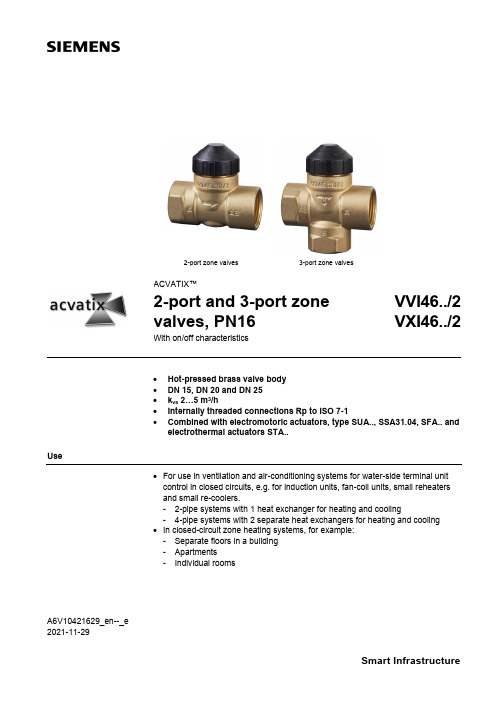
A6V10421629_en--_e 2021-11-292-port zone valves3-port zone valvesACVATIX™2-port and 3-port zone valves, PN16VVI46../2 VXI46../2With on/off characteristics• Hot-pressed brass valve body • DN 15, DN 20 and DN 25 • k vs 2…5 m 3/h• Internally threaded connections Rp to ISO 7-1•Combined with electromotoric actuators, type SUA.., SSA31.04, SFA.. and electrothermal actuators STA..Use• For use in ventilation and air-conditioning systems for water-side terminal unit control in closed circuits, e.g. for induction units, fan-coil units, small reheaters and small re-coolers.- 2-pipe systems with 1 heat exchanger for heating and cooling- 4-pipe systems with 2 separate heat exchangers for heating and cooling • In closed-circuit zone heating systems, for example: - Separate floors in a building - Apartments- Individual rooms2 / 10Type summaryTypeStock numberDNConnections PN classk vsA →AB [m 3/h]VVI46.15/2 S55249-V106 15 Internally threaded Rp162.15VVI46.20/2 S55249-V107 20 3.5 VVI46.25/2 S55249-V108 25 5.0TypeStock numberDNConnections PN classk vs 1) AB →A [m 3/h]k vs 1) AB →B [m 3/h] VXI46.15/2 S55249-V109 15 Internally threaded Rp162.151.5 VXI46.20/2 S55249-V110 20 3.52.5 VXI46.25/2 S55249-V111 25 5.03.5 VXI46.25T/2S55249-V112255.54.51)The k vs values in bypass B of the 3-port valves represent only 70 % of the k vs value in the straight-through control path AB → A. This compensates for the flow resistance of the heat exchanger or radiator, so keeping the overall flow rate100 as constant as possible.k vs = Nominal flow rate of cold water (5…30 °C) through the fully open valve (H 100), by a differentialpressure of 100 kPa (1 bar)OrderingWhen ordering, please specify the quantity, product name and number.The valves and actuators are delivered in separate packaging.The actuator SUA21/3, SSA31.04, SFA.. and STA.. must be ordered separately.The AL50 supporting ring (necessary for combination with SFA.. or SUA..) is included in the delivery of V..I46…See Revision number overview Revision number overview on page 10.ExampleProduct number Stock number Product nameQuantityVXI46.15/2S55249-V1093-port zone valve, PN16 DN15, kvs 2.15 1DeliveryRev. no.3 / 10Equipment combinations∆p max = Maximum permissible differential pressure across the valve’s control path, valid for the entireactuating range of the motorized valve (maximum recommended operating differential pressure) For noiseless operation, the value of 100 kPa should not be exceeded.∆p s = Maximum permissible differential pressure at which the motorized valve will close securelyagainst the pressure (close off pressure)1) ∆pmax(AB-B) is 50 kPa for VXI46.25T/21) SPST = single pole, single throw2)SSA31.04 could not be used with VVI46.25T/24832Z 01Technical design / mechanical design• Disc throttling element• Seat ring embedded in through-port• Seat machined into through-port and bypass• Reservoir for continuous lubrication of sealing rings •Return spring (to open position)Actuator overview4 / 10SizingExample:100 = 0.27 l/s ∆p v 100 = 9 kPak vs value required = 3.5 m 3/h∆p v 100= Differential pressure across the fully open valve and the valve's control path A → AB (2-port valves), AB → A (3-port diverting valves) by a volume flow100100= Volume flow through the fully open valve (H 100)∆p max= Maximum permissible differential pressure across the valve's control path, valid for theentire actuating range of the motorized valve100 kPa =1 bar≈10 mWC 1 m 3/h = 0.278 l/s water at 20 °C5 / 10Engineering notesRefer to Mounting notes and Commissioning notes . It is NOT allowed to put a shut off at the bypass port B.A strainer should be fitted upstream of the valve. This increases reliability.The direction of flow MUST be as indicated by the arrow, from A → AB.The direction of flow MUST be as indicated by the arrow, from AB → A and AB → B (diverting valves).RecommendationWarningWarning6 / 10Mounting notesThe specified direction of flow must be observed in all cases (refer to Engineering notes ).The mounting instructions 74 123 0114 0 B are enclosed with the packaging. The valve and actuator are easily assembled directly on site. There is no need for special tools or calibration.The AL501) supporting ring must be put into position before mounting the actuator SFA.. and SUA.. onto the valve.1) Included in deliveryOrientationAL50 supporting ringSIEMENSkvs5.0XYYMMAA 6V 10421629Z 017 / 10Commissioning notes In the straight-through control path A → AB, respectively AB → A the valve is opened by a return spring.The straight-through path can be closed manually with the manual adjustment button.With 3-port valves, this method can be used to open bypass B to 70 %. (exception: VXI46.25T/2)Maintenance notesV..I46../2 valves require no maintenance.When doing service work on the valve/actuator:• Deactivate the pump and turn off the power supply • Close the shutoff valves• Fully reduce the pressure in the piping system and allow pipes to completelycool downIf necessary, disconnect the electrical wires.Before putting the valve into operation again, make sure the manual knob or the actuator is correctly fitted.The stem sealing gland cannot be exchanged. In the case of leakage, the entire valve must be replaced. Contact your local office or branch.Disposal• Before disposal, the valve must be dismantled and separated into its various constituent materials.• Legislation may demand special handling of certain components, or it may be sensible from an ecological point of view. • Please observe current local legislation.WarrantyThe technical data given for these applications is valid only in conjunction with the Siemens actuators as detailed under Equipment combinations on page 2. Use with third-party actuators invalidates any warranty offered by Siemens Building Technologies HVAC Products.Manual adjustmentCautionStem sealing glandTechnical data8 / 109 / 10Dimensions 2-port valves 3-port valves VVI46../2VXI46../21)For seamless, round copper tubes according to DIN EN 1057Spare partsMultipack of 40 piecesRevision number overviewIssued by:Siemens Switzerland Ltd.Smart InfrastructureGlobal Headquarters Theilerstrasse 1aCH-6300 ZugSwitzerlandTel. +41 58-724 24 24/buildingtechnologies@ Siemens Switzerland Inc, 2014-2021 Delivery and technical specifications subject to change10 / 10。
西门子 两通及三通区域阀,PN16 说明书

Siemens Building Technologies
HVAC Products
阀门特性
1m3/h=在 20℃时水流量 0.278kg/s
两通阀,VV…46…
三通阀,VV…46…
可以用于通风和空调系统中闭式环路中水侧末端机组的控制,举例来
VXI46 … 三通
DN 连接
kVS A AB1)
[m3/h]
kVS
AB
A 1)
[m3/h]
kVS AB [m3/h]
A 1)
Δ PVmax Kpa
CE1N4842en
05.2003
Siemens Building Technologies
PN16 到 EN1333
线形 线形 线形
kVS 的 0…0.05% kVS 的 0…0.05% 最大 kVS 的 2…5%
允许介质
冷冻水,低温热水和含有防冻保护添加剂的水 推荐:水应该按标准 VDI2035 中要求处理
介质温度 可调范围 SV 允许的运行压力 额定行程
>1…110℃,或者短时间内最大 120℃ >10 如标准 VDI2173 中要求 1600kPa(16bar) 2.5mm
两通阀
三通阀
两通阀
三通阀
VVI46.15 至 VVI46.25 VXI46.15 至 VXI46.25 VVS146.15 至 VVS146.25 VXS146.15 至 VXS146.25
两通及三通区域阀,PN16
VVI46
VXI46 VVS46 VXS46
三通管操作流程

三通管操作流程The operation of the three-way valve is an essential process in the management of fluid flow in various industrial, commercial, and residential applications. 三通阀的操作是在各种工业、商业和居住应用中管理流体流动的重要过程。
Whether it's controlling the flow of water in a plumbing system or managing the distribution of gases in a chemical plant, the proper operation of three-way valves is crucial for ensuring the efficient and safe transfer of fluids. 无论是在管道系统中控制水流,还是管理化工厂中气体的分配,正确操作三通阀对于确保流体的高效和安全传输至关重要。
From understanding the basic principles of three-way valve operation to the practical steps of manipulating the valve in a real-world scenario, there are several key aspects and considerations to bear in mind. 从理解三通阀操作的基本原理到在实际场景中操纵阀门的实际步骤,有几个关键方面和考虑事项需要记住。
Therefore, it is essential to explore the operational flow of the three-way valve from various perspectives to gain a comprehensive understanding of its significance and functioning. 因此,有必要从不同的角度探讨三通阀的操作流程,以获取全面了解其重要性和功能。
Siemens 3LD 开关切换器说明书

3LD2113-0TK51 Page 2/9
05/05/2020
Subject to change without notice © Copyright Siemens
Operating frequency ● initial value ● Full-scale value
● motor drive ● Voltage trigger
Yes
3 4 mm 8 mm
No No
3LD2113-0TK51 Page 3/9
05/05/2020
Subject to change without notice © Copyright Siemens
Short circuit Conditional short-circuit current / with line-side fuse protection
Current Operating current ● at AC-23 A / at 690 V / rated value ● at AC-23 A / at 400 V / rated value ● at AC-22 A / at 690 V / rated value ● at AC-21 / at 690 V / rated value ● at AC-21 A / at 240 V / rated value ● at AC-21 A / at 440 V / rated value ● at AC-22 A / at 240 V / rated value ● at AC-22 A / at 440 V / rated value ● at AC-23 A / at 240 V / rated value ● at AC-23 A / at 440 V / rated value Operating current / of upstream fuse / rated value Let-through current / with closed switch ● at 440 V / for combination switch + gG fuse / maximum ● at 690 V / for combination switch + gG fuse / maximum permissible Short-time withstand current (Icw) ● limited to 1 s / rated value ● at 690 V / limited to 1 s / rated value
三通调节阀

三通调整阀三通调整阀,是由直行程电子式电动执行机构和采纳圆筒型薄壁窗口形阀芯的三通合流(分流)阀构成。
具有结构紧凑、重量轻、动作灵敏、流量特性精准明确,直接接受调整仪表输入的(4—20mADC0—10mADC或1—5VDC)等掌控信号及单相电源即可掌控运转,实现对工艺管路流体介质的自动调整掌控,广泛应用于精准明确控气体、液体、蒸汽等介质的工艺参数如压力、流量、温度、液位等参数保持在给定值。
适合于把一种流体通过三通阀分成二路流出或把两种流体经三通阀合并成一种流体的工况。
目录分类结构注意事项结构特点简介分类结构三通调整阀按流体的作用方式分为合流阀和分流阀两类。
合流阀有两个入口,合流后从一个出口流出。
分流阀有一个流体入口,经分流成两股流体从两个出口流出。
合流三通调整阀的结构与分流三通调整阀的结构仿佛。
其特点如下:1、三通调整阀有两个阀芯和阀座,结构与双座阀仿佛。
但三通调整阀中,一个阀芯与阀座间的流通面积加添时,另一个阀芯与阀座间的流通面积削减。
而双座阀中,两个阀芯和阀座间的流通面积是同时加添或削减的。
2、三通调整阀的气开和气关只能通过选择执行机构的正作用和反作用来实现。
双座阀的气开和气关的更改可直接将阀体或阀芯与阀座反装来实现。
3、三通调整阀用于需要流体进行配比的掌控系统时,由于它代替一个气开掌控阀和一个气关掌控阀,因此,可降低成本并削减安装空间。
4、三通调整阀也用于旁路掌控的场所,例如,一路流体通过换热器换热,另一路流体不进行换热。
当三通阀安装在换热器前时,采纳分流三通调整阀;当三通调整阀安装在换热器后时,采纳合流三通调整阀。
由于安装在换热器前的三通阀内流过的流体有相同温度,因此,泄漏量较小;安装在换热器后的三通阀内流过的流体有不同的温度,对阀芯和阀座的膨胀程度不同,因此,泄漏量较大。
通常,两股流体的温度差不宜超过150℃。
采纳阀笼结构的三通调整阀,带平衡孔,采纳阀笼导向。
因此,可大大降低不平衡力。
气动三通阀门使用说明书及维修手册
气动三通阀门使用说明书及维修手册气动三通阀门使用说明书及维修手册一、产品概述气动三通阀门是一种用于控制气体流动方向的设备,主要由阀体、阀盖、阀杆、阀芯等组成。
本产品广泛应用于工业自动化系统中,具有使用方便、自动化程度高等特点。
二、安全须知2.1 运输与搬运1) 在运输气动三通阀门时,需注意避免碰撞或挤压,以避免阀门零件损坏。
2) 搬运阀门时,应使用专用工具,并遵循正确的搬运方法和操作规程。
2.2 安装与调试1) 在安装之前,必须将气动三通阀门清洁干净,并检查阀体、阀盖、阀杆、阀芯等零部件是否有损坏。
2) 安装阀门时,应先根据系统布局确定合适的位置,并根据实际需要连接气源、管道等设备。
3) 安装完毕后,应进行阀门的调试工作,确保阀门无泄漏、顺畅运行。
2.3 使用与维护1) 在使用气动三通阀门时,应确保阀门能正常开启和关闭,并且阀门的控制信号与气源信号一致。
2) 定期对阀门进行维护保养,包括清洁阀体、阀芯,检查密封性能和润滑情况等。
3) 如发现阀门出现异常运行、泄漏等问题,应及时停止使用并进行维修。
三、维修手册3.1 拆解与装配1) 在拆解气动三通阀门之前,应切断气源,并排空内部气体。
2) 拆下阀杆与阀盖,并将阀芯取出进行清洗和检查。
3) 在装配之前,应检查阀门各部件的完好情况,确保无损坏或丢失。
3.2 零件更换1) 根据使用需要,如需更换阀杆、阀芯等零件,应选择符合规定规格的零件进行更换。
2) 零件更换时,应注意正确安装和调整,确保每个零件与阀门完全匹配并正常工作。
3.3 故障排除1) 当气动三通阀门出现异常运行,如无法开启或关闭、泄漏等问题时,应及时进行故障排除。
2) 故障排除应从阀门内部开始,检查阀体、阀盖、阀杆、阀芯等零部件是否损坏或灰尘积聚,需要时进行清洁或更换。
四、附件本文档涉及附件包括:1) 气动三通阀门技术参数表2) 安装示意图3) 零部件清单五、法律名词及注释1) 气动三通阀门:一种通过气动传动来控制气体流动方向的阀门型号或设备。
TC-WTF WLF 三通道多口球阀说明书
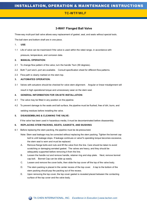
3-WAY Flanged Ball ValveThree-way multi-port ball valve allows easy replacement of gasket, seal, and seats without special tools. The ball stem and bottom shaft are in one piece.E:1.1 Life of valve can be maximized if the valve is used within the rated range, in accordance withpressure, temperature, and corrosion data.2.MANUAL OPERATION:2.1 To change flow pattern of the valve, turn the handle ?turn (90 degrees).2.2 Both T port and L port are available. Consult specification sheet for different flow patterns.2.3 Flow path is clearly marked on the stem top.3.AUTOMATED OPERATION:3.1 Valves with actuators should be checked for valve stem alignment. Angular or linear misalignment willresult in high operational torque and unnecessary wear on the stem seal.4.GENERAL INFORMATION FOR ON-SITE INSTALLATION:4.1 The valve may be fitted in any position on the pipeline.4.2 To prevent damage to the seats and ball surface, the pipeline must be flushed, free of dirt, burrs, andwelding residues before installing the valve.5.DISASSEMBLING & CLEANING THE VALVE:If the valve has been used in hazardous media, it must be decontaminated before disassembly.6.REPLACING STEM PACKING, SEATS, GASKETS, AND BUSHING6.1 Before replacing the stem packing, the pipeline must be de-pressurized.Note: Stem seal leakage may be corrected without replacing the stem packing. Tighten the bonnet cap bolt to until leakage stops. If leakage continues or valve?s operating torque becomes excessive,the stem seal is worn and must be replaced.A. Remove flange bolts and nuts and lift the valve from the line. Care should be taken to avoidscratching or damaging serrated gasket. The valves are heavy, and they should beadequately supported before removing it from the line.B. Loosen the handle nut and remove handle, retainer ring and stop plate. Next, remove bonnetcap bolt. Bonnet Cap can be slide up easily.C. Loosen and remove the cover bolts, then slide the top cover off the top of the valve body.D. The stem packing is placed in the center recess of the top cover. A tap to the bottom of thestem packing should pop the packing out of the recess.E. Upon removing the top cover, the top cover gasket is revealed placed between the contactingsurface of the top cover and the valve body.6.2 To replace the seats and the end cap gaskets, the end caps must be remove. We recommendthat seats and gaskets be replaced at the same time.A. Use a proper wrench, remove body bolt nuts on all three end caps. Slide off all three end caps. Seatsshould come out with the end caps. End cap gaskets may be attached to the valve body recess or itmay slide off with the end cap.B. Once the end caps are removed, the ball can be remove from the valve body. Extreme cautionshould be taken to avoid damaging the ball. After the ball is removed, the bottom busing is revealed. 7.VISUAL INSPECTION:7.1 Clean and inspect metal parts. It is not necessary to replace the ball unless the surface has signs ofabrasion or corrosion. We strongly recommend replacement of all soft parts whenever the valve isdisassembled for reconditioning. We provide replacement kits that contain all the replaceable parts.Note: The valve may be assembled and operated dry with any lubricant. However, a light lubrication will aid in assembly and reduce initial operating torque. Lubricant used must be acceptablewith the intended line fluid.8.ASSEMBLY8.1 Install seats on the end caps. Place the seats in the end caps recess such that the seat curvature is facingthe ball.8.2 Install gaskets on the end caps. The end cap gaskets should fit on the outer diameter of the end cap8.3 Replace the bottom bushing in the valve body cavity.8.4 Place ball on top of the busing. It should lay in the center of the valve body cavity.8.5 Carefully attach the end caps to the valve body. Screw in the nuts but do not tighten them.8.6 Tighten the nuts in a star pattern to the torque specified in T able 1. Extreme care must be exercisedduring adjustment of cap end nuts to make sure that complete engagement of the studs with bodyflange is maintained. There should be at least one stud thread exposed on each side.8.7 The next end cap to be tightened should be the one directly opposite the one that has been tighten.Follow the same procedure as outline in 8.6.8.8 Afterwards, tighten the remaining end cap in the manner as described above.8.9 Install the stem packing in the center recess of the top cover. Install the top cover gasket.8.10 Place the top cover back to the top of the valve body. Tighten the nuts in tar?pattern to the torquespecified in T able 1.8.11 Install the bonnet cap and screw in the bonnet cap bolt.8.12 Cycle the valve slowly, with a gentle back and forth motion, to build gradually to the full quarter turn.By cycling slowly, the seat lips will assume a permanent seal shape against the ball. A fast turningmotion, at this point, may cut the seats before they have a chance to form the proper seal.8.13 Test valve, if possible, prior to placing valve back into line position. If not properly secured, the valvecan separate from the pressure source, resulting in possible injury. Always join the valve tocompanion flanges of same pressure rating as valve and secure with a full set of flange bolts.TEST AS FOLLOWS:A. Secure valve to a test fixture by means of a mating flange with full bolting and a suitable gasket.MATERIALS LISTOrient valve so seat to be tested is facing up.B. Introduce 50 to 100 psig air. Partially cycle the valve, under pressure, then slowly close tomake sure the cavity is pressurized (use hearing protection). Pour water into the upper port to cover the ball and visually check for bubbles. If bubbles appear, pour the water out, cycle the valve several times and recheck. Tocheck for leakage in the other port, reverse the valve andintroduce air pressure to the port just checked.C. Check stem seal at this time by coating the stem top area with a water/soap solution. If leakageoccurs, tighten stem seal just until leakage stops.Valve SizeRequirementsTorque (N-M)1-1/2” ~ 2”408 2/1/2” ~ 4”500 6” ~8”1050 10 Consult Factory”Table 1 。
- 1、下载文档前请自行甄别文档内容的完整性,平台不提供额外的编辑、内容补充、找答案等附加服务。
- 2、"仅部分预览"的文档,不可在线预览部分如存在完整性等问题,可反馈申请退款(可完整预览的文档不适用该条件!)。
- 3、如文档侵犯您的权益,请联系客服反馈,我们会尽快为您处理(人工客服工作时间:9:00-18:30)。
SIEMENS 电动三通产温控品阀 使用手册二零零七年第二版 ( 提示:请妥善保管本手册,以备急需,遗失不补!)前言尊敬的客户: 您好,感谢您选用本公司为您提供的温控阀系列产品。
我 公 司 经 德 国 SIEMENS 楼 宇 科 技 公 司 正 式 授 权 代 理 , 并 被SIEMENS 公司评为优秀合作伙伴,负责 SIEMENS 楼宇科技公司暖通 空调控制类产品的技术推广、产品推广、技术服务以及产品销售和售后 服务工作。
在我们为您提供温控阀系列产品的同时,更为您展现出优质 的服务和专业的技术实力,以及敬业精神和全方位为客户着想的工作态 度。
在您选用我们的产品之时,我们已根据您的订货要求进行了参数和程序设定。
尽管如此,为了进一步保证设备正确安装、使用和维护保养及时, 仍建议您仔细阅读本《使用手册》。
如果您需要重新设定或更改参数,更应进一步阅读,如有疑问,可 致电您的供应商或与我们联系,我们的工程技术人员在接到您的咨询要 求后,一定会竭力为您提供满意答复。
公司全体员工再次感谢您对我们公司的信任与支持!注意事项1、SIEMENS 公司在不断的追求产品的优化和性能的改进,因此我们同时保留在没有作出通知的情况下对本版说明书进行修改的权利。
2、本着对用户负责的工作态度,本手册的编制过程中,我们尽可能地为用户的安装维护提供全面的指导和建议。
由于本产品使用现场的复杂性和多样性,本《使用手册》不可1能尽述,欢迎广大用户在使用过程中提出宝贵意见,以利于我们更好地改进服务工作。
3、公司不可能强调到所有潜在危险的情形。
因而,用户在使用时,除严格遵守本《手册》要求外,务请参考国内相关或近似标准的要求使用,不同标准之间有冲突时,请参考较 高级要求之标准。
4、本《使用手册》中所提及产品及使用说明是专门针对于暖通空调设备而言的,若用于 其它工况,建议由专业人员根据工艺要求进行控制逻辑分析,或与我公司经销商联系, 我们的工程技术人员一定会竭尽全力给您满意的答复和建议。
5、建议由经过培训的专业操作人员进行设备的安装、操作和维护。
6、本《手册》经 SIEMENS 产品专业技术人员审阅,请勿抄袭或随意摘引相关内容,若 由此造成用户使用和理解上的错误,SIEMENS 公司不负任何责任,甚至可能追诉责任。
7、在表明各种危害程度时,本手册中会使用标志性语言,其等级的定义如下所示:! 危险:可能导致操作人员人身伤害,或对系统设备造成损毁。
! 警告:可能导致设备失灵或设备本身损坏,并难以修复。
! 注意:可能导致设备控制不准确或严重影响设备寿命。
第一章 产品概述电动三通温控阀:西门子电动温控阀广泛应用于城市供暖、供气、空调、制冷等楼宇自动控制系统。
也适用于化工、 石油、冶金、电力、食品等行业的生产过程自动控制系统。
电动温控阀德国西门子原装控制器及电动执行器,结合我公司提供的压力自平衡式阀体,具有控 制精确,关断力大,自平衡防抱死等特点。
并可根据使用现场系统设备的不同灵活调整比例带, 积分时间等参数,使之与系统达到最佳匹配,可消除静差,运行平稳,反应灵敏,延长使用寿命。
控制器具有 PI、PID 调节功能,控制精确,多回路控制,功能多样,可实现流体流量、压力、压 差、温度、湿度、焓值和空气质量的控制。
执行器有电动机械式和电动液压式,带有手动和自动调节功能,调节灵敏,关断力大,流量特性 可调(线性等百分比)。
电动液压式执行器带断电自动复位保护功能,可接收 0-10V 或 4-20MA 的信号并带有阀位反馈功能。
2阀体的流量调节阀,适用于循环管路冷冻水,低压热水、生活热水、高压热水、海水、热油、和 蒸气的调节、线性好、可调比大、密封严密、耐高温、防汽蚀。
一、产品特点具有比例积分(PI)或比例积分、微分(PID)调节功能,控制稳定、精确。
a、针对不同的现场工况,可灵活调整控制参数,达到系统最优化。
b、可由控制器读取当前温度值及观察阀门工作状态。
c、可扩展功能,如远程设置、温度补偿、超温报警、昼夜/冬夏转换。
d、阀体密封采用 V 型环高温密封组件,防止了阀杆报死或泄漏的可能性。
e、阀杆或阀座配对研磨,确保泄露量远低于国家允许标准。
二、阀体结构 三、外形尺寸: 四、技术参数:第二章 指导安装第一步:检查: 1 阀体应按箭头指示顺热媒流向安装,不得装反。
2 阀门安装前必须彻底吹洗管道,去除焊渣及杂物。
3 系统预热时,先关闭阀前截止阀,打开旁通,至二次热媒温度升至接近要 求温度时,方可彻底关闭旁通,打开温控阀前截止阀,将温控阀投入运行。
第二步:执行器安装: (1) 将阀杆向上拉起 (2) 将执行器安装于阀体上 (3) 先用内六方或其它合适的工具预固定执行器底部于阀体连接环槽上。
! 警告:切不可先拧紧背死(4) 旋转执行器手动旋钮(SQX、SKD 系列)或手动摇柄(SKB、SKC 系列)将 执行器连接凹槽与阀杆顶部凹槽对正(注意:SKB、SKC 系列要先将执行器 下部连接内螺纹活节拆下,并将连接活节套于阀杆上。
)3(5) SQX、SKD 执行器连接: 用内六方紧固连接螺丝,直至执行器与阀杆紧密连接。
! 注意:(1)两侧螺丝均匀用力拧紧,不可拧偏,否则将产生扭力,可能导致阀杆变形或执行器支架断裂。
(2)连接凹槽一定要对正,否则行程不符或工作时将脱落。
(6) SKB、SKC 执行器的连接(见下图): A、 将连接卡环置于阀杆顶部凹槽中。
B、 将连接内螺纹活节提起,卡住卡环。
C、 将连接内螺纹活节沿逆时针方向旋转,背死。
D、 用手动旋钮(SQX 、SKD)或摇柄(SKB、SKC)将阀杆提起至自动状 态。
此时,执行器自动找正,然后将阀体连接环槽处螺栓背死。
警告:若未找! 正,则易产生应力,工作中可能导致 支架断裂!执行器与阀体的安装步骤(以SKB/C系列的执行器与阀体的连接举例):步骤一: 步骤二: 步骤三:! 警告:(1)整个安装过程中切勿碰伤阀杆(2)SKB、SKC 执行器与阀杆连接时 ,连接内螺纹连母一定要与执行 器丝同步相扣,若错位,将导致滑丝,且不可修复。
! 注意:(1)一定要将手动操作恢复至自动。
否则,执行器通电后不动作或造成损坏。
(2)系统若进行打压试验之前,一定要将执行器装于阀体上。
并使阀体处于手动开启状态,待试验完毕,务必将阀杆提起,恢复至自动状态。
第三步:出水温度传感器安装:1、浸入式温度传感器(QAE21) (1) 在换热器出口处附近开孔,焊丝座。
4丝座要求:G1/2"管螺纹、内丝。
(2) 丝座建议加工尺寸按管径匹配,丝座长度建议:见说明书后附图、表。
(3) 将传感器底部螺纹缠绕四氟胶带,沿顺时针方向固定于丝座上。
允许安装位置不允许安装的位置! 注意:密封需严密,防止漏水1、捆绑式温度传感器(QAD22)(1) 打开上盖,取出内部金属绑带(2) 将传感器贴于管道(注意方向)外壁(3) 用绑带固定紧后,结扣处套于传感器中紧固螺丝上(4) 用螺丝刀沿顺时针方向旋转,直至传感器紧固于管道上! 注意:此种安装方式只适用于≦DN150 的管道2、室外温度补偿传感器(QAC22):(1)安装于室外背阴处,且方便布线的位置。
(2)远离门、窗户等地方,且避开门窗上方。
(3)离地高度≥2.5m,避免闲人触摸。
(4)在选定的位置打孔、钉木梢。
(5)打开传感器前盖,用自攻丝将传感器固定后,盖上前盖。
第四步:控制器/电控箱安装1、控制器安装:控制器应装在光线充足,便于读数和操作的地方,一般安装在控制箱的DIN 导轨上。
2、电控箱安装:(1) 选择适当地点,一般为便于观察操作的墙面(2) 根据电控箱背部安装孔定位(3) 根据安装孔定位打膨胀螺栓(4) 将电控箱对正膨胀螺栓安上,将螺母背死5! 警告:电控箱安装处一定要远离易受潮或易滴漏水处第五步:接线控制器在电控箱内的对内和对外设备接线图1、传感器与控制器接线:(1) QAE21、QAD22 接线1) 打开 QAE21 传感器盒盖。
2) 从侧面接线孔处将信号线穿入。
3) 将 B 端子与控制器 X1 端子相连。
4) 将 M 端子与控制器上任意 M 端相连。
5) 检查端子是否有松脱,接线头是否有短接。
6) 将盖板扣上。
(2) QAC22 接线:步骤与 QAE21 基本相同,但需注意 B 端子接入控制器 X2 端子,M端子接法相同。
!注意:应防止凝结水或湿汽沿接线进入接线盒。
2、控制器与执行器接线:(1) 将执行器接线盖打开。
(2) 将执行器侧面敲落孔打开,将线引入线盒。
(3) 将执行器端子 G0 与控制器端子 G0 相接,端子 G 与控制器 G 相接,端子 Y 与控制器输出信号 Y1 相接。
(4) 将盖板恢复,并确认盖板周边密闭。
! 警告:(1) 去掉敲落孔盖板及接线时,切勿将线路板划伤!(2) 落孔处建议安装紧线箍或采取其它密封措施,避免凝水沿接线进入执行器,或湿气进入,将线路板烧坏!(3)盖板必须盖严,周边不能进湿气,否则将导致执行器损坏!6! 危险:切不可带电操作,否则有触电导致设备损坏或人身伤亡的危险!! 警告:请严格按随机所附接线图等资料接线!! 注意:(1)连接线建议选择二芯/三芯屏蔽信号线,直径≥0.75mm2。
(2)长度≦30m,若距离加长,建议屏蔽信号线加粗。
(4) 屏蔽信号线应尽量远离动力电缆及有信号干扰的电机等设备。
(5) 屏蔽信号线不可与动力电缆平行敷设。
! 注意:接线端子处防止短接。
3、电源供电接线: (1) 用测电笔检查电源线是否带电,严禁带电操作! (2) 接电源线火线/零线(L/N 线)分别与电控箱 L/N 端子连接。
(3) 将变压器输出(AC 24V)接入控制器端子 G/G0。
若用户使用我公司提 供的电控箱,则此线已接好。
! 注意:任何不按本手册要求的安装和造成的损坏,SIEMENS 公司将视为安装使用不当,若能修复,则需收取相应的成本费用。
第三章 调试指导提示:建议由经过专业培训的技术人员进行操作,任何不按本手册要求的操作都将可能会 造成设备损坏或影响使用效果和产品寿命。
一、 调试前的理论准备工作:1、 了解各部件的基本技术性能要求。
2、 了解各部件的功能。
3、 了解换热设备的工艺原理。
二、 调试前的操作准备: 1、确认一次热源彻底关闭。
2、检查接线是否有误。
3、打开系统二次侧,投入运行。
7LED 绿色显示 开 闪烁红色开 闪烁关功能 ·正常运行 ·行程校验进行中·行程校验错误处理 自动进行,没问题 等到校验结束(LED 停止闪烁)检查安装,重新开始行程校验 (通过短接校验孔)或更换电子元件·阀门内部阻塞检查阀门·无电源·电子元件故障 检查电源更换电子元件友情 提示: 系统 投入 使用时,首先将二次侧启动,并检查以下几项:(1) 循环管路阀门是否打开。