ds3500安装配置步骤
DS3500安装配置步骤
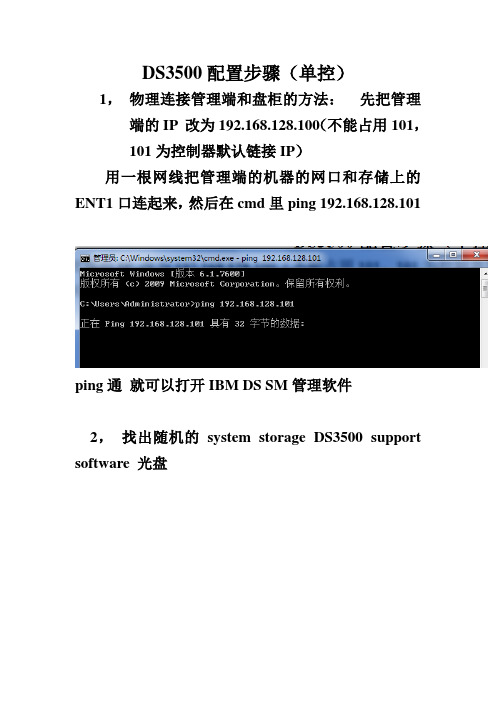
DS3500配置步骤(单控)1,物理连接管理端和盘柜的方法:先把管理端的IP 改为192.168.128.100(不能占用101,101为控制器默认链接IP)用一根网线把管理端的机器的网口和存储上的ENT1口连起来,然后在cmd里ping 192.168.128.101ping通就可以打开IBM DS SM管理软件2,找出随机的system storage DS3500 support software 光盘双击后第一界面点OK点NEXT继续NEXT然后点击NEXT继续NEXT点击OK继续NEXT弹出任何界面都OK然后点击INST ALL开始安装,安装完成,开始菜单里找到如下点DS storage manager client,打开管理软件如下图界面,右击小电脑图标,弹出三个选项选择Out-of-band management再第一个空白处输入A控制器的管理IP 如上,然后点击ADD ,当添加完成,会询问是否继续添加,点NO正常添加完成后如图系统会要求强制设置,密码复杂性要满足大小写加数字加特殊符号:如Abc!@#123<>设置成功就可以进入管理界面了如图单击Logical右击unconfigured capacity ,选择create arrayNEXTARRAY NAME 可以自定义,随便输入继续NEXT选择好之后finish 完成array创建点击yes,开始创建LUNNEXT选择好之后NEXT结束LUN的创建如需继续创建新的LUN 可以点击yes 如果不需要点击NO开始映射的步骤(mapping)选择DEFINE , HOST GROUP为创建主机组HOST 为单台主机定义一个主机NAME同样可以随意输入,然后NEXT识别完成后NEXT,选择主机的操作系统类型后,finish 完成选择DEFINE ADDITIONAL MAPPING,add完后close 关闭对话框映射完成后可以看到对应主机里的LUN现在可以重启服务器,打开磁盘管理,查看到映射过来的LUN,服务器里显示为磁盘N,如果服务器里多了个莫名其妙的几十M的小盘在SM的mapping里把Access remove掉右击Access 选择remove mapping输入yes 点击OK然后刷新下磁盘管理或重启服务器,几十M的小磁盘就消失了。
DELL NX3500(DSFS) 安装配置说明文档

Field Installation GuideRevision 0.6 JUN 28, 2011Objective.This document will outline the necessary steps and actions to install Dell NX3500 high availability(HA) configuration:•Prerequisites - all the preparation needed to install NX3500 at customer site•Cabling – NX3500 HA power/networking cabling information•Validation - NX3500 validation check (hardware/software)•Software Installation – NX3500 software installation steps•Best practices – NX3500 best practice for redundant and non-redundant configurationNote: This document is NOT intended to replace the full NX3500 admin guide provided by Dell Inc. Recommendation: Please print this document in color before installation.Prerequisites.Hardware:•Dell NX3500 racked in the servers environment•Laptop/workstation•CAT 5/6 cableSoftware:•Dell DSFS 1.0 installation CD•MD Storage Manager(MDSM) installed on laptop/workstation•NAS Configuration Utility (NASCU) installed on laptop / workstation - NASCU can be obtain from Site Information:•NAS appliance setup worksheet•Network connection to NAS cluster•Servers environment NAS cluster physical locationCustomer Network switch configuration:•Spanning Tree Portfast enabled•Flow control enabled•Jumbo frames (9216 MTU)NX3500 - Cabling.Step 1: Cabling – Power – BPS (Backup Power Supply): •Connect BPS power supply 1 (Right) to servers environment grid•Connect BPS power supply 2 (left) to servers environment grida. Remove the battery from the power module.b. Rotate the battery 180 degrees.c. Reinstall the battery in the power module.d. Attach the power module cover.Step 2: Cabling – Power – NAS Controller 0:•Connect power supply 2(Left) to BPS left power connection•Connect power supply 1 (right) to servers environment grid power source 1 Step 3: Cabling – Power – NAS Controller 1:•Connect power supply 2(Left) to BPS right power connection•Connect power supply 1 (right) to servers environment grid power source 2Drawing 1 – power and USB connectionStep 4: Cabling – Power – MD Storage:•Connect power supply 1 (left-#1) to servers environment grid power source 1•Connect power supply 2 (right -#4) to servers environment grid power source 2Drawing 2 – MD Storage 3200 back viewStep 5: Cabling – USB – NAS Controller0:•Connect USB cable to BPS left USB connection (Please refer to drawing 1, USB connection )Step 6: Cabling – USB – NAS Controller1:•Connect USB cable to BPS right USB connection (Please refer to drawing 1, USB connection) Step 7: Cabling – Networking – Interconnect – NAS Controller0: •Connect the first interconnect cable (BLUE) to controller 1 interconnect NIC (Please refer to drawing 3, peer connection)•Connect the second interconnect cable (BLUE) to controller 1 interconnect NIC (Please refer to drawing 3, peer connection)•Connect IDRAC CONNECTION (PURPLE) to customer network switch (Please refer to drawing 3, internal network)Step 8: Cabling – Networking – Interconnect – NAS Controller1: •Connect IDRAC CONNECTION (PURPLE) to customer network switch (Please refer to drawing 3, internal network)Step 9: Cabling – Networking – Client Network – NAS Controller0: •Connect one Client connection cables (GREEN) to first client network switch (Please refer to drawing 3, client connection)•Connect one Client connection cables (GREEN) to second client network switch (Please refer to drawing 3, client connection)Step 10: Cabling – Networking – Client Network – NAS Controller1: •Connect one Client connection cables (GREEN) to first client network switch (Please refer to drawing 3, client connection)•Connect one Client connection cables (GREEN) to second client network switch (Please refer to drawing 3, client connection)Step 11: Cabling – Networking – SAN Network – NAS Controller0: •Connect one SAN connection cables (PURPLE) to Network switch A (Please refer to drawing 3, SAN connection)•Connect one SAN connection cables (PURPLE) to Network switch B (Please refer to drawing 3, SAN connection)Step 12: Cabling – Networking – SAN Network – NAS Controller1: •Connect one SAN connection cables (PURPLE) to Network switch A (Please refer to drawing 3, SAN connection)•Connect one SAN connection cables (PURPLE) to Network switch B (Please refer to drawing 3, SAN connection)Step 13: Cabling – Networking – SAN Network – MD Storage:•Connect Four SAN connection cables (PURPLE) from Raid Controller 0 to customer SAN switch (Please refer to drawing 3, SAN connection)•Connect Four SAN connection cables (PURPLE) from Raid Controller 1 to customer SAN switch (Please refer to drawing 3, SAN connection)Step 14: Cabling – Networking – Client Network (management) – MD Storage: •Connect Raid Controller management connection cable (GREEN) from Raid Controller 0 to network switch (Please refer to drawing 3, Client connection)•Connect Raid Controller management connection cable (GREEN) from Raid Controller 1 to network switch (Please refer to drawing 3, Client connection)Drawing 3 –Redundant network connection diagramNX3500 – Validation (Hardware).Step 15: Validation – Power:Power up the following components:•BPS – Verify both power supply LEDs are in operational mode (Green).•MD Storage – Verify both power LEDs are in operational mode (Green).•NX3500 Controller 0 – Verify both power LEDs are in operational mode (Green).•NX3500 Controller 0 – Verify Server indication front LCD panel shows no errors.•NX3500 Controller 1 – Verify both power LEDs are in operational mode (Green).•NX3500 Controller 1 – Verify Server indication front LCD panel shows no errors.Step 16: Validation – Networking:•BPS – Verify USB connection LEDs are in operational mode (Green).•MD Storage – On network switch verify all connection ports LEDs are in operational mode.•NX3500 Controller 0 – Verify Interconnect connection LEDs are in operational mode.•NX3500 Controller 0 – On Client network switches, verify all connection ports LEDs are in operational mode.•NX3500 Controller 0 – On SAN network switches, verify all connection ports LEDs are in operational mode.•NX3500 Controller 1 – Verify Interconnect connection LEDs are in operational mode.•NX3500 Controller 1 – On Client network switches verify all connection ports LEDs are in operational mode.•NX3500 Controller 1 – On SAN network switches verify all connection ports LEDs are in operational mode.NX3500 – Installation.Step 17: Installation – MD Storage – Disk Group:•Connect your laptop/management station to the network switch•Ensure any firewall on the laptop/management station is disabled.•Ensure that the laptop/management station is configured for IPv6 support•Launch the MD Storage Manager (MDSM) software on the laptop/ management station•Go to “Tools-> Auto detect” to scan your network for MD storage devices.(if failed to connect use statics IP to connect , see below default IPs)•Choose your MD storage arrayThe default MD Storage array IPs are:RAID Controller 0: IP: 192.168.128.101 Subnet Mask: 255.255.255.0RAID Controller 1: IP: 192.168.128.102 Subnet Mask: 255.255.255.0•Set your laptop IP to the same subnet as the MD Storage array•Launch the MD Storage Manager (MDSM) software on the Laptop/ management station•Go to “Tools-> Auto detect” will scan your network for MD storage devices.•Choose your MD storage array•From the “Physical” tab right-click on the raid controller choose “Configure “and then choose “Ethernet Management Port”Choose Ethernet port 0 and then change the IP address, repeat this process for the port 1.•Configure ISCSI Host Ports - From the “Physical” tab right click on the raid controller, choose “Configure and then choose “ISCSI Host Ports”•Choose the ISCSI Host Port and assign IP s ,netmask and gateway information •Click on “Advanced Host Port Setting “ and change the MTU to 9000Click on the Setup tab and then click on configure storage arraySelect Create New Disk Group using unconfigured capacity and click next Click on Create disk groups and virtual disks and then click OK.Click NextSelect manual (Advanced) and click next Select the RAID type,Select the Drives, click on “Add”, Drives will show on the right side. Click on “Calculate Capacity”, if the size satisfies your needs, click on “Finish” to continueNote: minimum configuration is 200G per LUN and minimum 2 LUNSClick OK and repeat this process for the next Disk GroupStep 18: Installation – MD Storage – Virtual Disk:Create a minimum of two virtual disks dedicated for NAS storage, virtual disk must be exactly the same size •On the Logical tab, select an Unconfigured Capacity controller.•Select Virtual Disk and then click Create.Click NextEnter LUN name and click on Use recommended setting and then click FinishStep 19: Installation – MD Storage – Host Group:• Click the Mappings tab.• Right-click Default Group and define a host groupClick Yes for the next virtual disk and repeat the process, when done click No.Enter Host group name and click OkTo map all the LUNS to the host group Right click on the host group, and select “Define”, “additional mapping”Mark each LUN created and then click “Add” until all the LUNs are added.Results ScreenRight-click on the host group created, select “Define” , “Host” .Type Host, and click “Next”In the IQN field enter a string that will be changed after the nodes will be up.Click “add” and then click “Next”Select OS type LINUX then click “Next”Click FinishFollow the Host creation again for the second host in the NX3500 systemStep 20: Installation – NAS Configuration-NASCU:•From the management station/laptop access double-clicks the PowerVault NX3500 Configuration Utility icon.•Click NextStep 21: Installation – NAS Configuration-NASCU-Storage: •Enter one of the IPs configured on the MD array controller iSCSI ports.•Enter SAN MTU size: recommend jumbo frames (MTU: 9000) for optimal performance.Step 22: Installation – NAS Configuration-NASCU-Controllers:Enter NAS Controller MAC Addresses: This can be found on the System Identification slide out tab located underneath the front bezel of the controller. The back of the tab lists the “Embedded NIC 1MAC address”.Step 23: Installation – NAS Configuration-NASCU-Client Network:Enter the following IP from NAS appliance setup worksheet•Client Access VIP: This is the IP used to access CIFS and NFS shares•NAS Management VIP: This is the IP used to access the web and command line administration interfaces •Controller IPs: These are private maintenance IPs for each controller and should not be accessed by clients directly.•Gateway: A system on the client network that should be reachable and pingable at all times such as a domain controller or switch.Step 24: Installation – NAS Configuration-NASCU-Interconnect Network:Enter Internal IPs: These are used for internal communication between the controller pair. IPs specified must be grouped in two different subnets and be completely isolated from any other systems on the network.Ensure these IPs do not clash with other systems on your networkStep 25: Installation – NAS Configuration-NASCU-SAN Network:Enter SAN IPs: These are used for iSCSI communication with the backend storage device (PowerVault MD3xx0i). As a result, these IPs must be on the same subnets configured on the MD3xx0i storage array. iSCSI sessions will be established with the MD3xx0i storage array over the two subnets specified.Step 26: Installation – NAS Configuration-NASCU-Summary:All settings will be applied to your controllers after this point. Listed below is a checklist of items to review: • Ensure no duplicate IPs are present• Ensure no zero entriesStep 27: Installation – NAS Configuration-NASCU-Results:Upon successful configuration, the PowerVault NAS configuration utility presents you with the NAS controller IQNs required to complete the pairing to the backend MD storage device.Copy the IQNs for both controllers onto a notepad, as this has to be entered into MDSM.From the PowerVault MDSM for the array you plan to use for your NAS storage, perform the following actions: •Select Mappings tab.Click on host then right click, select “Manage Host Port Identifiers”Click on “replace” and replace the IQN with the one just generatedTo continue configure NX3500 File system please refer to the NX3500 – NAS ManagerConfiguration Guide in the Admin Guide.Enter the IQN number , andclick on “Replace”Click on “Close”Repeat this operation for theother host created on the MD .Appendix 1。
本特利3500安装与调试

1传感器的安装与调试1.1轴承振动传感器探头的安装6个φ8 mm灵敏度为7.87 V/rnm的涡流探头分别装于1号、2号、3号轴承处。
每个轴承处安装两只互成90°,垂直于轴承,探头与水平方向的夹角为45°,分别测量X、Y方向上的振动。
一般涡流传感器,涡流影响范围约为传感器线圈直径的三倍,因此传感器对应的测量宽度应为传感器直径的三倍,而且在传感器空间24mm范围内不应有其它金属物存在,否则会带来误差。
安装间隙电压应为传感器输出特性曲线确定的线形中点位而定,φ8 mm灵敏度为7.87 V/mm的探头,安装间隙电压为-9.75 V或1.2 mm左右。
由于传感器线形电压范围大大超过测量范围,所以安装间隙允许有较大的偏差,只要保证测量范围在线形段内即可,但为了满足故障诊断和可靠性的需要,一般要求安装电压9.75土0.2 V。
1.2轴向位移、高低压差胀传感器的安装轴向位移测的是推力轴承相对汽缸的轴向位移,在机组运行过程中,使动静部件之间保持一定的轴向间隙,避免汽轮机内部转动部件和静止部件之间发生摩擦和碰撞。
两只轴向位移传感器探头安装在2号轴承处,分别装于甲乙两侧,探头朝向低压缸方向安装探头型号为7200型φ14mm探头,灵敏度为3.937V/mm,前臵器供电电压为-24V。
大轴相对于汽缸的设计零点为止推轴承靠在工作瓦面为大轴零位。
在安装轴向位移和低压差胀传感器前,首先要把大轴推到零位,然后按要求安装。
轴向位移的量程范围为-2 mm一+ 2 mm,安装电压-9.75土0.2 V沾化电厂汽轮机膨胀相对死点在2号轴承处,高压缸转子膨胀在以2号轴承处为相对死点向前箱方向膨胀,低压缸转子膨胀在以2轴承处为相对死点向发电机方向膨胀。
高低压差胀探头为不带前臵器φ25 mm涡流探头,灵敏度为0.8 V/ mm,因为高低压差胀都是朝着发电机方向安装,要使高低缸差胀测量范围均在线形范围之内,按照探头线性中点及量程范围- 2--10 mm定位。
DS3500配置手册

1. 选择合适的主机型号产品编号描述数量1746A2S IBM System Storage DS3512 单控制器机型,2U高,含1个控制器模块,1Gb数据缓存,12个3.5寸热插拔磁盘槽位,标配2个6Gbps SAS主机接口,4个分区许可,热插拔冗余电源及风扇1746A2D IBM System Storage DS3512 冗余双控制器机型,2U高,含2个控制器模块互为冗余,每控制器1Gb数据缓存,12个3.5寸热插拔磁盘槽位,标配4个6Gbps SAS主机接口,4个分区许可,热插拔冗余电源及风扇1746A4S IBM System Storage DS3524 单控制器机型,2U高,含1个控制器模块,1Gb数据缓存,24个2.5寸热插拔磁盘槽位,标配2个6Gbps SAS主机接口,4个分区许可,热插拔冗余电源及风扇1746A4D IBM System Storage DS3524 冗余双控制器机型,2U高,含2个控制器模块互为冗余,每控制器1Gb数据缓存,24个2.5寸热插拔磁盘槽位,标配4个6Gbps SAS主机接口,4个分区许可,热插拔冗余电源及风扇2. 如果磁盘数量超出主机能容纳的磁盘槽位数,需要选配磁盘扩展单元产品编号描述数量1746A2E IBM System Storage EXP3512 磁盘扩展单元,2U高,含1个ESM,12个3.5寸热插拔磁盘槽位,热插拔冗余电源及风扇1746A4E IBM System Storage EXP3524 磁盘扩展单元,2U高,含1个ESM,24个2.5寸热插拔磁盘槽位,热插拔冗余电源及风扇69Y0245Environ Svcs Module (ESM)注1:如果所需磁盘较多,大盘和小盘扩展柜可以混用,磁盘总数不能超过96块注2:如果主机是双控制器型号,每个扩展单元中需要增加一个ESM模块3. 根据所需主机接口选配相应子卡产品编号描述数量68Y84312 端口 6Gb SAS 扩展子卡68Y84324 端口 8Gb FC 扩展子卡,每个子卡标配含2个SFP模块68Y84334 端口 1Gb iSCSI 扩展子卡注3:标配主机每个控制器含2个6Gbps SAS主机接口,每控制器有一个扩展子卡槽位,可选上述三种子卡其中之一,注4:双控制器型号,子卡必须成对配置,2个控制器必须配置相同的子卡4. 控制器升级选件产品编号描述数量68Y8479第二个控制器 (适用于单控机型升级使用)69Y28768Gb FC SW SFP模块68Y84342GB 缓存升级模块,控制器标配1GB缓存,通过此选件扩展为2GB5. 选择线缆产品编号描述数量39R6529IBM 1m SAS Cable39R6531IBM 3m SAS Cable39M56961M LC-LC 光纤线缆39M56975m LC-LC 光纤线缆39M569825m LC-LC 光纤线缆68Y7501OM3 Fiber Cable LC-LC 10m(10米万兆光纤线)68Y75024-Pk OM3 Fiber Cbl LC-LC 10m(4根10米万兆光纤线)39Y7928Power Cord, China(电源线)注5:如果服务器通过SAS HBA卡和DS3500 SAS端口相连,需根据主机数量配置SAS线缆注6:如果服务器通过FC HBA卡和DS3500 FC端口相连,需根据主机数量和距离等因素选配光纤线缆注7:OM3光纤线俗称万兆光纤线,信号衰减较小,传输距离为其他光纤线的4倍,价格较贵注8:如果连接扩展柜,单控制器时每增加1个扩展柜需要1根SAS线缆,双控制器时每增加1个扩展柜需要2根SAS线缆6. 操作系统连接许可(标配已含Windows系统连接许可)产品编号描述数量68Y8458AIX Host Kit (IBM小型机的连接许可)68Y8459Linux on Power Host Kit(IBM小型机使用Linux的连接许可)68Y8461HP/UX Host Kit(HP小型机的连接许可)7. 3.5寸磁盘选件,适用于DS3512/EXP3512产品编号描述数量49Y1856300GB 15K 3.5" HDD49Y1861450GB 15K 3.5" HDD49Y1866600GB 15K 3.5" HDD49Y1947600GB 15K 3.5" FDE HDD49Y18761TB 7.2K 3.5" NL HDD49Y18712TB 7.2K 3.5" NL HDD注9:与DS3000老一代产品不同,DS3500的所有可用硬盘均为SSG产品组,而不再和System x选件通用,请配置时格8. 2.5寸磁盘选件,适用于DS3524/EXP3524产品编号描述数量49Y1841146GB 15K 2.5" HDD49Y1836300GB 10K 2.5" HDD49Y1952300GB 10K 2.5" FDE HDD49Y1851500GB 7.2K 2.5" NL HDD9. 分区许可(标配已含4个分区)产品编号描述数量68Y84364 to 8 Partition Upgrade68Y84374 to 16 Partition Upgrade68Y84384 to 32 Partition Upgrade68Y84394 to 64 Partition Upgrade68Y84418 to 16 Partition Upgrade68Y84428 to 32 Partition Upgrade68Y84438 to 64 Partition Upgrade68Y844516 to 32 Partition Upgrade68Y844616 to 64 Partition Upgrade68Y844832 to 64 Partition Upgrade10. 其他选件产品编号描述数量69Y2871Turbo Performance,将DS3500升级至Turbo版68Y8490Full Disk Encryption (FDE) 磁盘加密技术许可68Y8451FlashCopy Base (4个每卷,64个每系统)68Y8452FlashCopy 8/64 Upgrade(8个每卷,64个每系统)68Y8453Volume Base (最大128个每系统,其中8个可同时运行)68Y8454FlashCopy / Volume Copy (相当于68Y8451+68Y8453)68Y8455Remote Mirroring Base (最高8个镜像对)关于价格:1. 请进EMS查询Bid Ref价格2. 咨询三家总代:SRIT, Weida和EDIDS3512每控4个84个1G + 68Y8432+ 68Y8433DS3524每控制器4个6Gbps SAS主机端口每控制器4个8Gbps FC端口和2个6Gbps SAS主机端口+ 68Y8432每控制器4个1Gbps iSCSI端口和2个6Gbps SAS主机端口注:由于DS3500配置组合较多,下面仅以DS3512双控制器,配置FC子卡为例,参数仅供参考,请根据实际配项目RAID控制器缓存主机接口注:其他参考参数-标配单控型号注:其他参考参数-标配双控型号注:其他参考参数-配置SAS子卡注:其他参考参数-配置iSCSI子卡后端磁盘通道支持的硬盘类型支持的最大硬盘数量当前实配硬盘类型及数量(举例,请根据实际配置修改)注:DS3500可支持的磁盘类型包括RAID 支持存储分区支持的最大LUN数量随机I/O读写性能性能(IOPS)顺序读写带宽(MB/s)磁盘快照(FlashCopy)卷拷贝(VolumCopy)远程镜像(Remote Mirroring)大容量LUN支持硬件磁盘加密风扇和电源机架安装尺寸管理软件保修下面仅以1. 选择合适的主机型号产品编号181494H181498H2. 如果磁盘数超过16个,需要根据磁盘数量选配扩展柜产品编号181492H3. SATA磁盘选件产品编号43W971444X245859Y55364. 光纤通道磁盘选件产品编号40K682042D041044X245059Y54605. 磁盘数量超过32块时需要配置磁盘连接许可产品编号68Y750368Y75046. 连接服务器的许可(标配包含Windows系统连接许可)产品编号68Y751268Y751368Y751468Y751568Y751668Y75177. 分区许可(标配2分区)产品编号68Y751868Y751968Y752068Y752168Y752268Y752368Y752468Y752568Y752668Y752768Y752868Y75298. 线缆产品编号39M5696 39M5697 39M5698 68Y750168Y750239Y79289. 其他选件产品编号68Y750568Y750668Y750768Y750868Y750968Y751068Y7511描述数量DS3950 Express Model 94,3U 高度,冗余双控制器,每控制器含2GB 专用数据缓存,每控制器2个8Gb 光纤通道主机接口,总计提供4个8Gbps 光纤通道主机接口,提供16个3.5寸热插拔磁盘槽位,可支持光纤通道磁盘或SATA 磁盘混插使用,冗余热插拔电源及风扇DS3950 Express Model 98,3U 高度,冗余双控制器,每控制器含4GB 专用数据缓存,每控制器2个8Gb 光纤通道主机接口及2个1Gb iSCSI 主机接口,总计提供4个8Gbps 光纤通道主机接口及4个1Gb iSCSI 主机接口,提供16个3.5寸热插拔磁盘槽位,可支持光纤通道磁盘或SATA 磁盘混插使用,冗余热插拔电源及风扇描述数量EXP395 磁盘扩展单元,3U 高度,16个3.5寸热插拔磁盘槽位,冗余电源及风扇描述数量750 GB/7.2K SATA E-DDM 1000 GB/7.2K SATA E-DDM 2000 GB/7.2K SATA E-DDM描述数量4 Gbps FC, 146.8 GB/15K E-DDM 4 Gbps FC, 300 GB/15K E-DDM 4 Gbps FC, 450 GB/15K E-DDM 4 Gbps FC, 600 GB/15K E-DDM描述数量DS3950 Attach 33-64 Drives DS3950 Attach 65-112 Drives 描述数量DS3950 Linux/Intel Host Kit (Intel 架构服务器安装Linux 系统的连接许可)DS3950 VMware ESX Host Kit (VMware 连接许可)DS3950 AIX/VIOS Host Kit (IBM P 系列小型机AIX 操作系统连接许可)DS3950 SUN Host Kit (Oracle-SUN Solaris 系统连接许可)DS3950 HPUX Host Kit (HP-UX 系统连接许可)DS3950 Linux on Power Host (IBM P 系列小型机Linux 操作系统连接许可)描述数量DS3950 2-4 Stg. Part.- Fld DS3950 2-8 Stg. Part.- Fld DS3950 4-8 Stg. Part.- Fld DS3950 4-16 Stg. Part.- Fld DS3950 8-16 Stg. Part.- Fld DS3950 8-32 Stg. Part.- Fld DS3950 8-64 Stg. Part.- Fld DS3950 16-32 Stg. Part.- Fld DS3950 16-64 Stg. Part.- Fld DS3950 32-64 Stg. Part.- Fld DS3950 32-128 Stg. Par.- Fld DS3950 64-128 Stg. Par.- Fld描述数量选择合适的主机型号如果磁盘数超过16个,需要根据磁盘数量选配扩展柜SATA磁盘选件 光纤通道磁盘选件 磁盘数量超过32块时需要配置磁盘连接许可 连接服务器的许可(标配包含Windows系统连接许可)分区许可(标配2分区)1m LC-LC 光纤线缆5m LC-LC 光纤线缆25m LC-LC 光纤线缆OM3 Fiber Cable LC-LC 10m(10米万兆光纤线)4-Pk OM3 Fiber Cbl LC-LC 10m(4根10米万兆光纤线)Power Cord, China (PRC) 电源线描述数量DS3950 FlashCopyDS3950 FlashCpy 4-8 FC UpgdeDS3950 VolumeCopyDS3950 Flash/VolumeCopyDS3950 Enh. Remote MirrorDS3950 Enh.RemMr 32-64 UpgdeEXP810 to DS3950 Attach (允许DS3950连接EXP810扩展柜)注:以下参数仅供参考,请根据实际配置酌情修改。
3500基因测序仪操作流程

3500基因测序仪操作流程一、启动仪器1.按下仪器的电源键,当仪器指示灯为绿色时表明仪器正常开启。
2.打开与仪器连接的计算机,点击Ctrl+Alt+Delete界面,点击Administrator,输入密码:Administrator。
等待Daemon(隐藏图标),Server Monitor程序完全启动,Server Monitor图标上出现绿色对号时表示连接成功。
3.打开3500 Data Collection 软件,出现3500 Log In 登录界面,输入用户名和密码,本机用户名为:Administrator,密码为:Administrator1,点击“OK”,打开软件。
检查所有耗材的剩余用量、仪器的信息、耗材的使用信息以及仪器维护提示灯信息。
4. 确认检测阴性、阳极缓冲液在刻度线以上,以及确认所有耗材已恢复至室温。
注:3500测序所用到的阳极缓冲液、阴极缓冲液在仪器上可存放一周,POP 胶在仪器上存放一周后需置于2-8℃保存,洗液为一次性消耗品,不可重复使用。
5. 将阴性缓冲液、阳极缓冲液、洗液等耗材安装至仪器上后,点击refresh,确认所有耗材均为有效状态。
二、仪器维护1. 于软件主界面点击Dashbord,于菜单栏中选择Maintenance Wizards选项。
2. 将装有阳极缓冲液的耗材从仪器中取下,安装没有阳极缓冲液的容器,选择WASH pumper chamber and chanels选项,按照仪器指示,开始清洗管路并重新给毛细管灌胶直至完成全部操作。
3. 从Maintenance进入Spatial界面,按图示指示进行空间定位。
结果应满足如下要求:①峰高大致相同(大于6000);②峰型尖锐,左右堆成;③橙色十字在峰顶端;④峰间距为13-16。
当结果满足要求时,选择“Accept Results”,否则,选择“Reject Results”,重新进行空间定位。
4. 从Maintenance进入Spectral界面,按图示指示进行光谱校准。
本特利3500安装与调试
1传感器的安装与调试1.1轴承振动传感器探头的安装6个φ8 mm灵敏度为7.87 V/rnm的涡流探头分别装于1号、2号、3号轴承处。
每个轴承处安装两只互成90°,垂直于轴承,探头与水平方向的夹角为45°,分别测量X、Y方向上的振动。
一般涡流传感器,涡流影响范围约为传感器线圈直径的三倍,因此传感器对应的测量宽度应为传感器直径的三倍,而且在传感器空间24mm范围内不应有其它金属物存在,否则会带来误差。
安装间隙电压应为传感器输出特性曲线确定的线形中点位而定,φ8 mm灵敏度为7.87 V/mm的探头,安装间隙电压为-9.75 V或1.2 mm左右。
由于传感器线形电压范围大大超过测量范围,所以安装间隙允许有较大的偏差,只要保证测量范围在线形段内即可,但为了满足故障诊断和可靠性的需要,一般要求安装电压9.75土0.2 V。
1.2轴向位移、高低压差胀传感器的安装轴向位移测的是推力轴承相对汽缸的轴向位移,在机组运行过程中,使动静部件之间保持一定的轴向间隙,避免汽轮机内部转动部件和静止部件之间发生摩擦和碰撞。
两只轴向位移传感器探头安装在2号轴承处,分别装于甲乙两侧,探头朝向低压缸方向安装探头型号为7200型φ14mm探头,灵敏度为3.937V/mm,前臵器供电电压为-24V。
大轴相对于汽缸的设计零点为止推轴承靠在工作瓦面为大轴零位。
在安装轴向位移和低压差胀传感器前,首先要把大轴推到零位,然后按要求安装。
轴向位移的量程范围为-2 mm一+ 2 mm,安装电压-9.75土0.2 V沾化电厂汽轮机膨胀相对死点在2号轴承处,高压缸转子膨胀在以2号轴承处为相对死点向前箱方向膨胀,低压缸转子膨胀在以2轴承处为相对死点向发电机方向膨胀。
高低压差胀探头为不带前臵器φ25 mm涡流探头,灵敏度为0.8 V/ mm,因为高低压差胀都是朝着发电机方向安装,要使高低缸差胀测量范围均在线形范围之内,按照探头线性中点及量程范围- 2--10 mm定位。
DG Star 3500快速安装手册

DG Star 3500快速安装手册一、系统基本构造中心站组成结构图:如上图可以看到标准四扇区中心站的基本构成:主要分为室内和室外两部分。
室外由四个AP组成完成360°的覆盖,内含基带信号处理、中频、射频和扇区天线(90°×8°),每个AP和室内通过两条线连接,一为进行电源传输的室外五类线(和AP连接端为RJ-45接口,需现场制作),一为进行数据传输的室外尾纤(和AP连接端为MT-RJ接口)。
室内由四个1U的设备模块PDU(电源分配模块)、MUX(数据复用模块)、Fiber Patch (尾纤接续模块)和APC(AP控制模块)组成,相互之间的数据都采用数据尾纤;PDU从电源系统引入-48VDC,然后分别给APC、MUX和四个AP进行供电;MUX将四个AP的数据信号整合为一路骨干上联信号(A TM155M),同时将APC和四个AP的控制信息进行交换以控制整个基站的正常运作;Fiber Patch实际上就是一个小ODF,起到美观作用;APC 通过MUX的数据交换以实现对四个AP和整个基站的控制,并且提供10/100Base-T接口以便于进行配置管理。
最基本的中心站即如上所述,网络侧直接通过A TM155M(SDH/SONET)端口(多模SC,如有必要需加单/多模转换或接头转换)和运营商的骨干传输网进行连接,各远端站汇聚到本上联端口的业务通过A TM VC进行隔离,只需认真确认骨干侧的VC和DG Star 3500侧的业务VC一一对应即可。
如果用户要求在中心站直接提供E1或10/100Base-T接口,则我们提供A TM交换机将A TM VC映射到相应的E1或10/100Base-T接口;目前在网运行的主要在移动、网通提供了高鸿AM100和中兴的M1000两种A TM交换机,在联通则直接通过A TM155M接口直接和骨干网进行连接。
远端站组成结构图:无论是原来的CPE,还是新型的CPE,都采用室内室外结构。
IBMDS存储的配置步骤
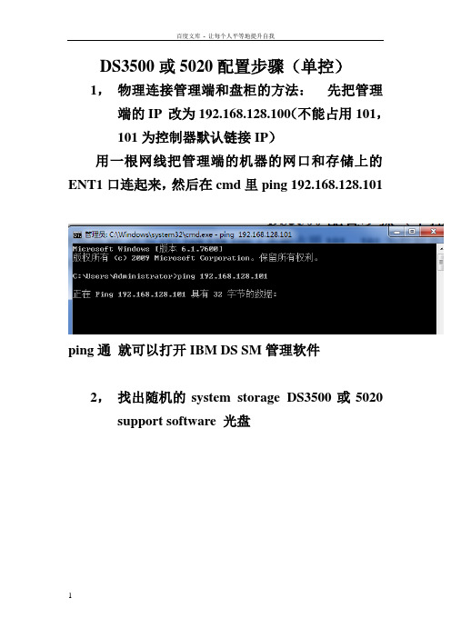
DS3500或5020配置步骤(单控)1,物理连接管理端和盘柜的方法:先把管理端的IP 改为192.168.128.100(不能占用101,101为控制器默认链接IP)用一根网线把管理端的机器的网口和存储上的ENT1口连起来,然后在cmd里ping 192.168.128.101ping通就可以打开IBM DS SM管理软件2,找出随机的system storage DS3500或5020 support software 光盘双击后第一界面点OK 点NEXT继续NEXT然后点击NEXT继续NEXT点击OK继续NEXT弹出任何界面都OK然后点击INSTALL开始安装,安装完成,开始菜单里找到如下点DS storage manager client,打开管理软件如下图界面,右击小电脑图标,弹出三个选项选择Out-of-band management再第一个空白处输入A控制器的管理IP 如上,然后点击ADD ,当添加完成,会询问是否继续添加,点NO正常添加完成后如图系统会要求强制设置,密码复杂性要满足大小写加数字加特殊符号:如Abc!@#123<>设置成功就可以进入管理界面了如图单击Logical右击unconfigured capacity ,选择create arrayNEXTARRAY NAME 可以自定义,随便输入继续NEXT选择好之后finish 完成array创建点击yes,开始创建LUNNEXT选择好之后NEXT结束LUN的创建如需继续创建新的LUN 可以点击yes 如果不需要点击NO开始映射的步骤(mapping)选择DEFINE , HOST GROUP为创建主机组HOST 为单台主机定义一个主机NAME同样可以随意输入,然后NEXT识别完成后NEXT,选择主机的操作系统类型后,finish 完成选择DEFINE ADDITIONAL MAPPING,add完后close 关闭对话框映射完成后可以看到对应主机里的LUN现在可以重启服务器,打开磁盘管理,查看到映射过来的LUN,服务器里显示为磁盘N,如果服务器里多了个莫名其妙的几十M的小盘在SM的mapping里把Access remove掉右击Access 选择remove mapping输入yes 点击OK然后刷新下磁盘管理或重启服务器,几十M的小磁盘就消失了。
- 1、下载文档前请自行甄别文档内容的完整性,平台不提供额外的编辑、内容补充、找答案等附加服务。
- 2、"仅部分预览"的文档,不可在线预览部分如存在完整性等问题,可反馈申请退款(可完整预览的文档不适用该条件!)。
- 3、如文档侵犯您的权益,请联系客服反馈,我们会尽快为您处理(人工客服工作时间:9:00-18:30)。
DS3500配置步骤(单控)
1,物理连接管理端和盘柜的方法:先把管理端的IP 改为192.168.128.100(不能占用101,101为控制器默认链接IP)
用一根网线把管理端的机器的网口和存储上的ENT1口连起来,然后在cmd里ping 192.168.128.101
ping通就可以打开IBM DS SM管理软件
2,找出随机的system storage DS3500 support software 光盘
双击后第一界面
点OK
点NEXT
继续NEXT
然后点击NEXT
继续NEXT
点击OK
继续NEXT
弹出任何界面都OK然后
点击INSTALL
开始安装,安装完成,开始菜单里找到如下
点DS storage manager
client,打开管理软件
如下图界面,右击小电脑图标,弹出三个选项
选择Out-of-band management
再第一个空白处输入A控制器的管理IP 如上,然后点击ADD ,当添加完成,会询问是否继续添加,点NO
正常添加完成后如图
系统会要求强制设置,密码复杂性要满足大小写加数字加特殊符号:如Abc!@#123<>
设置成功就可以进入管理界面了
如图
单击Logical
右击unconfigured capacity ,选择create array
NEXT
ARRAY NAME 可以自定义,随便输入继续NEXT
选择好之后finish 完成array创建
点击yes,开始创建LUN
NEXT
选择好之后NEXT
结束LUN的创建
如需继续创建新的LUN 可以点击yes 如果不需要点击NO
开始映射的步骤(mapping)
选择DEFINE , HOST GROUP为创建主机组HOST为单台主机
定义一个主机NAME同样可以随意输入,然后NEXT
识别完成后NEXT,选择主机的操作系统类型后,finish 完成
选择DEFINE ADDITIONAL MAPPING
,add完后close 关闭对话框
映射完成后可以看到对应主机里的LUN
现在可以重启服务器,打开磁盘管理,查看到映射过来的LUN,服务器里显示为磁盘N, 如果服务器里多了个莫名其妙的几十M的小盘在SM的mapping里把Access remove掉
右击Access 选择remove mapping
输入yes 点击OK
然后刷新下磁盘管理或重启服务器,几十M的小磁盘就消失了。
至此,配置结束。