齿轮箱培训文件翻译
机械零件齿轮中英文对照外文翻译文献
(文档含英文原文和中文翻译)中英文资料对照外文翻译Machine Parts (I)GearsGears are direct contact bodies, operating in pairs, that transmit motion and force from one rotating shaft to another or from a shaft to a slide (rack), by means of successively engaging projections called teeth.Tooth profiles. The contacting surfaces of gear teeth must be aligned in such a way that the drive is positive; i.e., the load transmitted must not depend on frictional contact. As shown in the treatment of direct contact bodies, this requires that thecommon normal to the surfaces not to pass through the pivotal axis of either the driver or the follower.As it is known as direct contact bodies, cycloidal and involute profiles profiles provide both a positive drive and a uniform velocity ratio;i.e., conjugate action.Basic relations. The smaller of a gear pair is called the pinion and the larger is the gear. When the pinion is on the driving shaft the pair is called the pinion and the larger is the gear. When the pinion is on the driving shaft the pair acts as a speed reducer; When the gear drives, the pair is a speed incrreaser. Gears are more frequently used to reduce speed than to increase it.If a gear having N teeth rotates at n revolutions per minute, the product N*n has the dimension “teeth per minute”. This product must be the same for both members of a mating pair if each tooth acquires a partner from the mating gear as it passes through the region of tooth engagement.For conjugate gears of all types, the gear ratio and the speed ratio are both given by the ratio of the number of teeth on the gear to the number of teeth on the pinion. If a gear has 100 teeth and a mating pinion has 20, the ratio is 100/20=5. Thus the pinion rotates five times as fast as the gear, regardless of the gear. Their point of tangency is called the pitch point, and since it lies on the line of centers, it is the only point at which the profiles have pure roling contact. Gears on nonparallel, non-intersecting shafts also have pitch circles, but the rolling-pitch –circle concept is not valid.Gear types are determined largely by the disposition of the shafts; in addition, certain types are better suited than others for large speed changes. This means that if a specific disposition of the shafts is required, the type of gear will more or less be fixed. On the other hand, if a required speed change demands a certain type, the shaft positions will also be fixed.Spur gears and helical gears. A gear having tooth elements that are straight and parallel to its axis is known as a spur gear. A spur pair can be used to connect parallel shafts only.If an involute spur pinion were made of rubber and twisted uniformly so that the ends rotated about the axis relative to one another, the elements of the teeth, initially straight and parallel to the axis, would become helices. The pinion then in effect would become a helical gear.Worm and bevel gears. In order to achieve line contact and improve the load carrying capacity of the crossed axis helical gears, the gear can be made to curvepartially around the pinion, in somewhat the same way that a nut envelops a screw. The result would be a cylindrical worm and gear. Worms are also made in the shape of an hourglass, instead of cylindrical, so that they partially envelop the gear. This results in a further increase in load-carrying capacity.Worm gears provide the simplest means of obtaining large ratios in a single pair. They are usually less efficient than parallel-shaft gears, however, because of an additional sliding movement along the teeth.V-beltThe rayon and rubber V-belt are widely used for power transmission. Such belts are made in two series: the standard V-belt and the high capacity V-belt. The belts can be used with short center distances and are made endless so that difficulty with splicing devices is avoided.First, cost is low, and power output may be increased by operating several belts side by side. All belts in the drive should stretch at the same rate in order to keep the load equally divided among them. When one of the belts breaks, the group must usually be replaced. The drive may be inclined at any angle with tight side either top or bottom. Since belts can operate on relatively small pulleys, large reductions of speed in a single drive are possible.Second,the included angle for the belt groove is usually from 34°to 38°.The wedging action of the belt in the groove gives a large increase in the tractive force developed by the belt.Third,pulley may be made of cast iron, sheet steel, or die-cast metal. Sufficient clearance must be provided at the bottom of the groove to prevent the belt from bottoming as it becomes narrower from wear. Sometimes the larger pulley is not grooved when it is possible to develop the required tractive force by running on the inner surface of the belt. The cost of cutting the grooves is thereby eliminated. Pulleys are on the market that permit an adjustment in the width of the groove. The effective pitch diameter of the pulley is thus varied, and moderate changes in the speed ratio can be secured.Chain DrivesThe first chain-driven or “safety” bicycle appeared in 1874, and chains were used for driving the rear wheels on early automobiles. Today, as the result of modern design and production methods, chain drives that are much superior to their prototypes are available, and these have contributed greatly to thedevelopment of efficient agricultural machinery, well-drilling equipment, and mining and construction machinery. Since about 1930 chain drives have become increasingly popular, especially for power saws, motorcycle, and escalators etc.There are at least six types of power-transmission chains; three of these will be covered in this article, namely the roller chain, the inverted tooth, or silent chain, and the bead chain. The essential elements in a roller-chain drive are a chain with side plates, pins, bushings (sleeves), and rollers, and two or more sprocket wheels with teeth that look like gear teeth. Roller chains are assembled from pin links and roller links. A pin link consists of two side plates connected by two pins inserted into holes in the side plates. The pins fit tightly into the holes, forming what is known as a press fit. A roller link consists of two side plates connected by two press-fitted bushings, on which two hardened steel rollers are free to rotate. When assembled, the pins are a free fit in the bushings and rotate slightly, relative to the bushings when the chain goes on and leaves a sprocket.Standard roller chains are available in single strands or in multiple strands, In the latter type, two or more chains are joined by common pins that keep the rollers in the separate strands in proper alignment. The speed ratio for a single drive should be limited to about 10∶1; the preferred shaft center distance is from 30 to 35 times the distance between the rollers and chain speeds greater than about 2500 feet (800 meters) per minute are not recommended. Where several parallel shafts are to be driven without slip from a single shaft, roller chains are particularly well suited.An inverted tooth, or silent chain is essentially an assemblage of gear racks, each with two teeth, pivotally connected to form a closed chain with the teeth on the inside, and meshing with conjugate teeth on the sprocket wheels. The links are pin-connected flat steel plates usually having straight-sided teeth with an included angle of 60 degrees. As many links are necessary to transmit the power and are connected side by side. Compared with roller-chain drives, silent-chain drives are quieter, operate successfully at higher speeds, and can transmit more load for the same width. Some automobiles have silent-chain camshaft drives.Bead chains provide an inexpensive and versatile means for connecting parallel or nonparallel shafts when the speed and power transmitted are low. The sprocket wheels contain hemispherical or conical recesses into which the beads fit. The chains look like key chains and are available in plain carbon and stainless steel and also in the form of solid plastic beads molded on a cord. Bead chains are used oncomputers, air conditioners, television tuners, and Venetian blinds. The sprockets may be steel, die-cast zinc or aluminum, or molded nylon.Machine Parts (II)FastenerFasteners are devices which permit one part to be joined to a second part and, hence, they are involved in almost all designs.There are three main classifications of fasteners, which are described as follows:(1) Removable. This type permits the parts to be readily disconnected without damaging the fastener. An example is the ordinary nut-and-bolt fastener.(2) Semi permanent. For this type, the parts can be disconnected, but some damage usually occurs to the fastener. One such example is a cotter pin.(3) Permanent. When this type of fastener is used, it is intended that the parts will never be disassembled. Examples are riveted joints and welded joints.The importance of fasteners can be realized when referring to any complex product. In the case of the automobile, there are literally thousands of parts which are fastened together to produce the total product. The failure or loosening of a single fastener could result in a simple nuisance such as a door rattle or in a serious situation such as a wheel coming off. Such possibilities must be taken into account in the selection of the type of fastener for the specific application.Nuts, bolts, and screws are undoubtedly the most common means of joining materials. Since they are so widely used, it is essential that these fasteners attain maximum effectiveness at the lowest possible cost. Bolts are, in reality, carefully engineered products with a practically infinite use over a wide range of services.An ordinary nut loosens when the forces of vibration overcome those of friction. In a nut and lock washer combination, the lock washer supplies an independent locking feature preventing the nut from loosening. The lock washer is useful only when the bolt might loosen because of a relative change between the length of the bolt and the parts assembled by it. This change in the length of the bolt can be caused by a number of factors-creep in the bolt, loss of resilience, difference in thermal expansion between the bolt and the bolted members, or wear. In the above static cases, the expanding lock washer holds the nut under axial load and keeps the assembly tight. When relative changes are caused by vibration forces, the lock washer is not nearly as effective.Rivets are permanent fasteners. They depend on deformation of their structure for their holding action. Rivets are usually stronger than the thread-type fastener and are more economical on a first-cost basis. Rivets are driven either hot or cold,depending upon the mechanical properties of the rivet material. Aluminum rivets, for instance, are cold-driven, since cold working improves the strength of aluminum. Most large rivets are hot-driven, however.ShaftVirtually all machines contain shafts. The most common shape for shafts is circular and the cross section can be either solid or hollow (hollow shafts can result in weight savings).Shafts are mounted in bearings and transmit power through such devices as gears, pulleys, cams and clutches. These devices introduce forces which attempt to bend the shaft; hence, the shaft must be rigid enough to prevent overloading of the supporting bearings. In general, the bending deflection of a shaft should not exceed 0.01 in. per ft. of length between bearing supports.For diameters less than 3 in., the usual shaft material is cold-rolled steel containing about 0.4 percent carbon. Shafts are either cold-rolled or forged in sizes from 3 in. to 5 in. .For sizes above 5 in. , shafts are forged and machined to size. Plastic shafts are widely used for light load applications. One advantage of using plastic is safety in electrical applications, since plastic is a poor conductor of electricity.Another important aspect of shaft design is the method of directly connecting one shaft to another. This is accomplished by devices such as rigid and flexible couplings.BearingA bearing can be defined as a member specifically designed to support moving machine components. The most common bearing application is the support of a rotating shaft that is transmitting power from one location to another. Since there is always relative motion between a bearing and its mating surface, friction is involved. In many instances, such as the design of pulleys, brakes, and clutches, friction is desirable. However, in the case of bearings, the reduction of friction is one of the prime considerations:Friction results in loss of power, the generation of heat, and increased wear of mating surfaces.The concern of a machine designer with ball bearings and roller bearings is fivefold as follows:(1) Life in relation to load; (2) stiffness, i.e. deflections under load;(3) friction; (4) wear; (5) noise. For moderate loads and speeds the correct selection ofa standard bearing on the basis of load rating will usually secure satisfactoryperformance. The deflection of the bearing elements will become important where loads are high, although this is usually of less magnitude than that of the shafts or other components associated with the bearing. Where speeds are high special cooling arrangements become necessary which may increase frictional drag. Wear is primarily associated with the introduction of contaminants, and sealing arrangements must be chosen with regard to the hostility of the environment.Notwithstanding the fact that responsibility for the basic design of ball bearings and roller bearings rests with the bearing manufacturer, the machine designer must form a correct appreciation of the duty to be performed by the bearing and be concerned not only with bearing selection but with the conditions for correct installation.The fit of the bearing races onto the shaft or onto the housings is of critical importance because of their combined effect on the internal clearance of the bearing as well as preserving the desired degree of interference fit. Inadequate interference can induce serious trouble from fretting corrosion. The inner race is frequently located axially by abutting against a shoulder. A radius at this point is essential for the avoidance of stress concentration and ball races are provided with a radius or chamfer to allow space for this.A journal bearing, in its simplest form, is a cylindrical bushing made of a suitable material and containing properly machined inside and outside diameters. The journal is usually the part of a shaft or pin that rotates inside the bearing.Journal bearings operate with sliding contact, to reduce the problems associated with sliding friction in journal bearings, a lubricant is used in conjunction with compatible mating materials. When selecting the lubricant and mating materials, one must take into account bearing pressures, temperatures and also rubbing velocities. The principle function of the lubricant in sliding contact bearings is to prevent physical contact between the rubbing surfaces. Thus the maintenance of an oil film under varying loads, speeds and temperature is the prime consideration in sliding contact bearings.Introduction to Machinery DesignMachinery design is either to formulate an engineering plan for the satisfaction of a specified need or to solve an engineering problem. It involves a range of disciplines in materials, mechanics, heat, flow, control, electronics and production.Machinery design may be simple or enormously complex, easy or difficult, mathematical or nonmathematical, it may involve a trivial problem or one of great importance. Good design is the orderly and interesting arrangement of an idea to provide certain results or effects. A well-designed product is functional, efficient, and dependable. Such a product is less expensive than a similar poorly designed product that does not function properly and must constantly be repaired.People who perform the various functions of machinery design are typically called industrial designers. He or she must first carefully define the problem, using an engineering approach, to ensure that any proposed solution will solve the right problem. It is important that the designer begins by identifying exactly how he or she will recognize a satisfactory alternative, and how to distinguish between two satisfactory alternatives in order to identify the better. So industrial designers must have creative imagination, knowledge of engineering, production techniques, tools, machines, and materials to design a new product for manufacture, or to improve an existing product.In the modern industrialized world, the wealth and living standards of a nation are closely linked with their capabilities to design and manufacture engineering products. It can be claimed that the advancement of machinery design and manufacturing can remarkably promote the overall level of a country’s industrization. Our country is playing a more and more vital role in the global manufacturing industry. To accelerate such an industrializing process, highly skilled design engineers having extensive knowledge and expertises are needed.Machinery ComponentsThe major part of a machine is the mechanical system. And the mechanical system is decomposed into mechanisms, which can be further decomposed into mechanical components. In this sense, the mechanical components are the fundamental elements of machinery. On the whole, mechanical components can be classified as universal and special components. Bolts, gear, and chains are the typical examples of the universal components, which can be used extensively in different machines across various industrial sectors. Turbine blades, crankshaft and aircraftpropeller are the examples of the special components, which are designed for some specific purposes.Mechanical Design ProcessProduct design requires much research and development. Many concepts of an idea must be studied, tried, refined, and then either used or discarded. Although the content of each engineering problem is unique, the designers follow the similar process to solve the problems.Recognition of NeedSometimes, design begins when a designer recognizes a need and decides to do something about it. The need is often not evident at, all; recognition is usually triggered by a particular adverse circumstance or a set of random circumstances, which arise almost simultaneously. Identification of need usually consists of an undefined and vague problem statement.Definition of ProblemDefinition of problem is necessary to fully define and understand the problem, after which it is possible to restate the goal in a more reasonable and realistic way than the original problem statement. Definition of the problem must include all the specifications for the thing that is to be designed. Obvious items in the specifications are the speeds, feeds, temperature limitations, maximum range, expected variation in the variables, and dimensional and weight limitations.SynthesisThe synthesis is one in which as many alternative possible design approaches are sought, usually without regard for their value or quality. This is also sometimes called the ideation and invention step in which the largest possible number of creative solutions is generated. The synthesis activity includes the specification of material, addition of geometric features, and inclusion of greater dimensional detail to the aggregate design.AnalysisAnalysis is a method of determining or describing the nature of something by separating it into its parts. In the process the elements, or nature of the design, are analyzed to determine the fit between the proposed design and the original design goals.EvaluationEvaluation is the final proof of a successful design and usually involves thetesting of a prototype in the laboratory. Here we wish to discover if the design really satisfies the needs.The above description may give an erroneous impression that this process can be accomplished in a linear fashion as listed. On the contrary, iteration is required within the entire process, moving from any step back to any previous step, in all possible combinations, and doing this repeatedly.PresentationCommunicating the design to others is the finial, vital presentation step in the design process. Basically, there are only three means of communication. These are the written, the oral, and the graphical forms. A successful engineer will be technically competent and versatile in all three forms of communication. The competent engineer should not be afraid of the possibility of not succeeding in a presentation. In fact, the greatest gains are obtained by those willing to risk defeat.Contents of Machinery DesignMachinery design is an important technological basic course in mechanical engineering education. Its objective is to provide the concepts, procedures, data, and decision analysis techniques necessary to design machine elements commonly found in mechanical devices and systems; to develop engineering students’ competence of machine design that is the primary concern of machinery manufacturing and the key to manufacture good products.Machinery design covers the following contents:Provides an introduction to the design process, problem formulation, safety factors.Reviews the material properties and static and dynamic loading analysis, including beam, vibration and impact loading.Reviews the fundamentals of stress and defection analysis.Introduces static failure theories and fracture-mechanics analysis for static loads.Introduces fatigue-failure theory with the emphasis on stress-life approaches to high-cycle fatigue design, which is commonly used in the design of rotation machinery.Discusses thoroughly the phenomena of wear mechanisms, surface contact stresses, and surface fatigue.Investigates shaft design using the fatigue-analysis techniques.Discusses fluid-film and rolling-element bearing theory and application.Gives a thorough introduction to the kinematics, design and stress analysis of spur gears, and a simple introduction to helical, bevel, and worm gearing.Discusses spring design including helical compression, extension and torsion springs.Deals with screws and fasteners including power screw and preload fasteners.Introduces the design and specification of disk and drum clutches and brakes.机械零件(I)齿轮齿轮是直接接触,成对工作的实体,在称为齿的凸出物的连续啮合作用下,齿轮能将运动和力从一个旋转轴传递到另一个旋转轴,或从一个轴传递到一个滑块(齿条)。
kissSoft齿轮计算书中文翻译
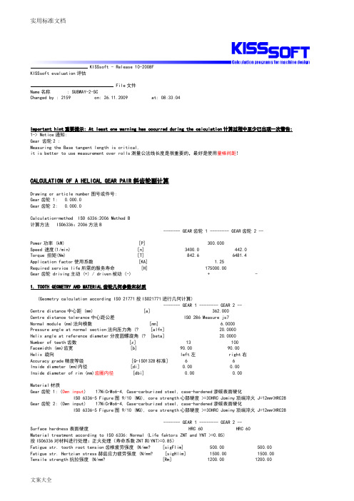
KISSsoft - Release 10-2008FKISSsoft evaluation评估File文件Name名称 : SUBWAY-2-SCChanged by : 2159 on: 26.11.2009 at: 08:33:04Important hint重要提示: At least one warning has occurred during the calculation计算过程中至少已出现一次警告: 1-> Notice通知:Gear 齿轮2 :Measuring the Base tangent length is critical,it is better to use measurement over rolls测量公法线长度是很重要的,最好是使用量棒间距!CALCULATION OF A HELICAL GEAR PAIR斜齿轮副计算Drawing or article number图号或件号:Gear齿轮 1: 0.000.0Gear齿轮 2: 0.000.0Calculation-method ISO 6336:2006 Method B计算方法 ISO6336:2006方法B------- GEAR齿轮 1 -------- GEAR齿轮 2 --Power功率 (kW) [P] 300.000Speed 速度(1/min) [n] 3400.0 442.0Torque 扭矩(Nm) [T] 842.6 6481.4Application factor使用系数 [KA] 1.25Required service life所需的服务寿命 [H] 175000.00Gear齿轮 driving主动 (+) / driven被动 (-) + -1. TOOTH GEOMETRY AND MATERIAL齿轮几何参数和材质(Geometry calculation according ISO 21771按ISO21771进行几何计算)------- GEAR 1 -------- GEAR 2 --Centre distance中心距 (mm) [a] 362.000Centre distance tolerance中心距公差 ISO 286 Measure js7Normal module (mm)法向模数 [mn] 6.0000Pressure angle at normal section法向压力角 (? [alfn] 20.0000Helix angle at reference diameter分度圆螺旋角 (? [beta] 20.0000Number of teeth齿数 [z] 13 100Facewidth (mm)齿宽 [b] 90.00 90.00Helix 旋向 left左 right右Accuracy grade精度等级 [Q-ISO1328标准] 6 6Inside diameter (mm)内径 [di] 0.00 0.00Inside diameter of rim (mm)齿圈内径 [dbi] 0.00 0.00Material材质Gear齿轮 1: (Own input) 17NiCrMo6-4, Case-carburized steel, case-hardened渗碳表面硬化ISO 6336-5 Figure图 9/10 (MQ), core strength心部硬度 >=30HRC Jominy顶端淬火 J=12mm<HRC28 Gear齿轮 2: (Own input) 17NiCrMo6-4, Case-carburized steel, case-hardened渗碳表面硬化ISO 6336-5 Figure图 9/10 (MQ), core strength心部硬度 >=30HRC Jominy顶端淬火 J=12mm<HRC28------- GEAR 1 -------- GEAR 2 --Surface hardness表面硬度 HRC 60 HRC 60Material treatment according to ISO 6336: Normal (Life faktors ZNT and YNT >=0.85)按ISO6336对材料进行处理:正火处理(寿命系数ZNT和YNT>=0.85)Fatigue str. tooth root tension齿根疲劳强度 (N/mm? [sigFlim] 500.00 500.00Fatigue str. Hertzian stress赫兹应力疲劳强度 (N/mm? [sigHlim] 1500.00 1500.00Yield point 屈服点(N/mm? [Rp] 850.00 850.00 Youngs modulus弹性模量 (N/mm? [E] 206000 206000 Poisson's ratio泊松比 [ny] 0.300 0.300 Average roughness, Ra, tooth flank平均粗糙度,齿面 (祄) [RAH] 0.60 0.60 Mean roughness height, Rz, flank峰谷平均值,齿面 (祄) [RZH] 4.80 4.80 Mean roughness height, Rz, root峰谷平均值,齿根 (祄) [RZF] 20.00 20.00Tool or reference profile of gear 1齿轮1的刀具参数 :Reference Profile1.25 / 0.25 / 1.0 JISAddendum factor齿顶高系数 [haP*] 1.000Dedendum coefficient齿根高系数 [hfP*] 1.250Tip radius factor刀尖圆弧半径系数 [rhoaP*] 0.000Root radius factor根圆半径系数 [rhofP*] 0.250Tip form height coefficient齿廓系数 [hFaP*] 0.000Protuberance height factor凸角系数 [hprP*] 0.000Protuberance angle凸角角度 [alfprP] 0.000Ramp angle [alfKP] 0.000not toppingTool or reference profile of gear 2齿轮2的刀具参数:Reference Profile1.25 / 0.25 / 1.0 JISAddendum factor齿顶高系数 [haP*] 1.000Dedendum coefficient齿根高系数 [hfP*] 1.250Tip radius factor刀尖圆弧半径系数 [rhoaP*] 0.000Root radius factor根圆半径系数 [rhofP*] 0.250Tip form height coefficient齿廓系数 [hFaP*] 0.000Protuberance height factor凸角系数 [hprP*] 0.000Protuberance angle凸角角度 [alfprP] 0.000Ramp angle [alfKP] 0.000not toppingSum of reference profile gears:Dedendum reference profile (module) [hfP*] 1.250 1.250Tooth root radius Refer. profile (module)[rofP*] 0.250 0.250Addendum Reference profile (module) [haP*] 1.000 1.000Protuberance height (module) [hprP*] 0.000 0.000Protuberance angle (? [alfprP] 0.000 0.000Buckling root flank height (module) [hFaP*] 0.000 0.000Buckling root flank angle (? [alfKP] 0.000 0.000Type of profile modification:修形类型for high load capacity gearboxe用于承载能力高的齿轮箱Tip relief齿顶修缘 (祄) [Ca] 21.00 26.00Type of lubrication润滑方式 oil bath lubrication油池润滑Type of oil滑油类型 Oil润滑油: ISO-VG 320Lubricant base润滑剂基油 Mineral-oil base矿物油基Kinem. viscosity oil at 40 癈40℃时动粘度 (mm?s) [nu40] 320.00Kinem. viscosity oil at 100 癈100℃时动粘度 (mm?s) [nu100] 22.00FZG-Test A/8.3/90 (ISO14653-1) FZG试验 [FZGtestA] 12Specific density at 15 癈 15℃时的比重 (kg/dm? [roOil] 0.900Oil temperature (癈) 油温 [TS] 70.000ambient temperature (癈)环境温度 [TU] 20.000------- GEAR齿轮 1 -------- GEAR 2 --Overall transmission ratio总传动比 [itot] -7.692Gear ratio齿轮速比 [u] 7.692Transverse module (mm)端面模数 [mt] 6.385Pressure angle at Pitch circle节圆压力角 (? [alft] 21.173Working transverse pressure angle有效端面压力角 (? [alfwt] 21.675[alfwt.e/i] 21.687 / 21.664Working pressure angle at normal section法向有效压力角 (? [alfwn] 20.472Helix angle at operating pitch diameter工作节圆直径的螺旋角 (?[betaw] 20.063Reference centre distance分度圆中心距 (mm) [ad] 360.756Sum of the Addendum modification齿顶高变动和 [Summexi] 0.2096Profile shift coefficient 齿廓变位系数 [x] 0.1330 0.0766Tooth thickness齿厚 (Arc圆弧) (module模数) [sn*] 1.6676 1.6266Modification of tip diam.齿顶圆直径修正 (mm) [k] -0.014 -0.014 Reference diameter分度圆直径 (mm) [d] 83.006 638.507Base diameter基圆直径 (mm) [dB] 77.403 595.404Tip diameter齿顶圆直径 (mm) [da] 96.574 651.398(mm) [da.e/i] 96.574 / 96.564 651.398 / 651.388Tip diameter allowances齿顶圆直径误差 (mm) [Ada.e/i] 0.000 / -0.010 0.000 / -0.010Tip chamfer/ tip rounding齿顶倒角/圆角(mm) [hK] 0.000 0.000Tip form circle (mm) [dFa] 96.574 651.398(mm) [dFa.e/i] 96.574 / 96.564 651.398 / 651.388Operating pitch diameter工作节径 (mm) [dw] 83.292 640.708(mm) [dw.e/i] 83.299 / 83.285 640.758 / 640.658Root diameter根圆直径 (mm) [df] 69.602 624.426Generating Profile shift coefficient [xE.e/i] 0.1170 / 0.1078 0.0366 / 0.0183Manufactured root diameter with xE (mm) [df.e/i] 69.410 / 69.300 623.946 / 623.726Theoretical tip clearence理论齿顶间隙 (mm) [c] 1.500 1.500Effective tip clearence有效齿轮顶间隙 (mm) [c.e/i] 1.884 / 1.712 1.684 / 1.568Active root diameter有效根圆直径 (mm) [dNf] 77.468 631.238(mm) [dNf.e/i] 77.476 / 77.462 631.295 / 631.187Root form diameter渐开线起始点直径(mm) [dFf] 77.403 627.180(mm) [dFf.e/i] 77.403 / 77.403 626.763 / 626.573Reserve (dNf-dFf)/2 储备(mm) [cF.e/i] 0.037 / 0.030 2.361 / 2.212Addendum齿顶高 (mm) [ha] 6.784 6.446(mm) [ha.e/i] 6.784 / 6.779 6.446 / 6.441Dedendum齿根高 (mm) [hf] 6.702 7.040(mm) [hf.e/i] 6.798 / 6.853 7.281 / 7.390Roll angle at dFa (? dFa处展开角度 [xsi_dFa.e/i] 42.750 / 42.738 25.426 / 25.424Roll angle to dNa (? dNa处展开角度 [xsi_dNa.e/i] 42.750 / 42.738 25.426 / 25.424Roll angle to dNf (? dNf处展开角度 [xsi_dNf.e/i] 2.490 / 2.244 20.192 / 20.160Roll angle at dFf (? dFf处展开角度 [xsi_dFf.e/i] 0.029 / 0.029 18.839 / 18.780Tooth depth齿深 (mm) [H] 13.486 13.486Virtual gear no. of teeth当量齿轮齿数 [zn] 15.428 118.676Normal Tooth thickness at Tip cyl. (mm) [san] 3.643 4.855齿顶圆法向齿厚 (mm) [san.e/i] 3.569 / 3.517 4.681 / 4.595Normal Tooth space as Tip cylinder (mm) [efn] 0.000 4.287齿顶圆法向齿距 (mm) [efn.e/i] 0.000 / 0.000 4.313 / 4.325Max. sliding speed at tip齿顶处最大滑动速度 (m/s) [vga] 5.429 5.548 Specific sliding at the tip齿顶单位滑动比 [zetaa] 0.528 0.907 Specific sliding at the root齿根单位滑动比 [zetaf] -9.784 -1.119 Sliding factor on tip齿顶处滑动系数 [Kga] 0.366 0.374Sliding factor on root齿根处滑动系数 [Kgf] -0.374 -0.366Pitch节距 (mm) [pt] 20.059Base pitch基圆节径 (mm) [pbt] 18.705Transverse pitch on contact-path 啮合线上的端面节径(mm) [pet] 18.705Lead height (mm) [pz] 716.461 5511.239Axial pitch轴向节径 (mm) [px] 55.112Length of path of contact啮合线长度 (mm) [ga, e/i] 27.284 (27.361 / 27.186)Length T1-A, T2-A (mm) T1-A, T2-A长度 [T1A, T2A] 1.593( 1.515/ 1.682) 132.111(132.111/132.099) Length T1-B (mm) T1-B长度 [T1B, T2B] 10.171(10.171/10.163) 123.533(123.456/123.618) Length T1-C (mm) T1-C长度 [T1C, T2C] 15.382(15.373/15.391) 118.322(118.254/118.390) Length T1-D (mm) T1-D长度 [T1D, T2D] 20.298(20.221/20.387) 113.406(113.406/113.394) Length T1-E (mm) T1-E长度 [T1E, T2E] 28.876(28.876/28.868) 104.828(104.750/104.913) Length T1-T2 (mm) T1-T2长度 [T1T2] 133.704 (133.627 / 133.781) Diameter of single contact point B (mm)单啮合线B的直径[d-B] 80.031(80.031/80.027) 644.630(644.571/644.695)Diameter of single contact point D (mm) 单啮合线D的直径[d-D] 87.402(87.331/87.485) 637.142(637.142/637.133) Addendum contact ratio齿顶高接触比 [eps] 0.721( 0.722/ 0.721) 0.737( 0.741/ 0.733)Minimal length of contact line啮合线最小长度 (mm) [Lmin] 127.068Transverse contact ratio端面接触比 [eps_a] 1.459Transverse contact ratio, effective有效端面接触比 [eps_a.e/m/i] 1.463 / 1.458 / 1.453 Overlap ratio重叠比 [eps_b] 1.633Total contact ratio, effective有效总接触比 [eps_g.e/m/i] 3.096 / 3.091 / 3.0862. FACTORS OF GENERAL INFLUENCE通用影响系数------- GEAR 1 -------- GEAR 2 --Nominal circum. force at pitch circle (N)节圆的公称圆周力[Ft] 20301.8Axial force轴向力 (N) [Fa] 7389.3Radial force径向力 (N) [Fr] 7863.5Normal force法向力 (N) [Fnorm] 22991.3Tangent.load at p.c.d.per mm (N/mm) (N/mm)节圆直径上每mm的切向载荷[w] 225.58Only for information: Forces at the pitch-circle :仅供参考:节圆力Nominal circumferential force法向圆周力 (N)[Ftw] 20232.1Axial force 轴向力 (N) [Faw] 7389.3Radial force径向力 (N) [Frw] 8041.2Circumferential speed pitch d.. (m/sec) [v] 14.78节圆直径处的圆周速度Running in value y.a (祄) [ya] 0.6Correction coefficient修正系数 [CM] 0.800G ear body coefficient [CR] 1.000Reference profile coefficient [CBS] 0.975Material coefficient材料系数 [E/Est] 1.000Singular tooth stiffness (N/mm/祄) [c'] 12.762Meshing spring stiffness (N/mm/祄)啮合弹性刚度 [cgalf] 17.151Meshing spring stiffness (N/mm/祄) 啮合弹性刚度 [cgbet] 14.579Reduced mass (kg/mm)质量减少 [mRed] 0.024Resonance speed (min-1)共振转速 [nE1] 19616Nominal speed (-)公称速度 [N] 0.173Subcritical range亚临界范围Bearing distance l of pinion shaft (mm)齿轮轴轴承距 [l] 180.000Distances of pinion shaft (mm)齿轮轴间距 [s] 18.000Outside diameter of the pinion shaft (mm)齿轮轴外径[dsh] 75.000load according ISO 6336/1 Diagram 16 [-] 40:a), 1:b), 2:c), 3:d), 4:e) ISO6336/1图16的载荷Coefficient K' following ISO 6336/1 Diagram 13 按ISO6336/图13系数K′[K'] -1.00Without support effect无支撑效应Tooth trace deviation (active) (祄) [Fby] 6.69from deformation of shaft轴变形引起的齿轮轨迹偏差(祄)(工作) [fsh*B1] 1.22 Tooth curve: width-crowned [Cbeta = 0.5*(fma+fsh)]Position of Contact pattern: Favorablefrom production tolerances (祄) 接触斑点位置:对生产公差有利 [fma*B2] 9.22 Tooth trace deviation, theoretical (祄) [Fbx] 7.88Running in value y.b (祄) 齿轮轨迹偏差,理论 [yb] 1.18Dynamic coefficient动载系数 [KV] 1.048Face coefficient齿面系数 - flank齿面 [KHb] 1.165- Tooth root齿根 [KFb] 1.139- Scuffing胶合 [KBb] 1.165Transverse coefficient横向系数– flank齿面 [KHa] 1.061- Tooth root齿根 [KFa] 1.061- Scuffing胶合 [KBa] 1.061Helix angle coefficient scuffing螺旋角系数,胶合 [Kbg] 1.289No of load changes (in mio.)载荷变化次数 [NL] 35700.000 4641.0003. TOOTH ROOT STRENGTH齿根强度------- GEAR齿轮 1 -------- GEAR齿轮 2 -- Calculation of Tooth form coefficients according method: B 齿形系数计算按方法B(Calculate tooth shape coefficient YF with addendum mod. x)(计算齿形系数YF时用齿顶修正量x)Stress correction factor应力修正系数 [YS] 1.98 2.44working angle (? 工作角 [alfen] 18.39 20.35Bending lever arm (mm)弯曲力臂 [hF] 5.81 7.08Tooth thickness at root (mm)齿根处齿厚 [sFn] 11.45 13.86Tooth root radius (mm)齿根半径 [roF] 2.76 2.02(hF* = 0.968/1.180 sFn* = 1.908/2.310 roF* = 0.459/0.336 dsFn = 71.41/626.10 alfsFn = 30.00/30.00)Contact ratio factor接触比系数 [Yeps] 1.000Helix angle factor螺旋角系数 [Ybet] 0.833Deep tooth factor [YDT] 1.000Gear rim factor齿圈系数 [YB] 1.000 1.000Effective facewidth (mm) [beff] 90.00 90.00Nominal shear stress at tooth root (N/mm? 齿根名义剪切应力[sigF0] 99.93 101.21Tooth root stress (N/mm? 齿根应力 [sigF] 158.18 160.21Permissible bending stress at root of Test-gear被测齿轮齿根允许的弯曲应力support factor支撑系数 [YdrelT] 0.996 1.008Surface-factor表面系数 [YRrelT] 0.957 0.957Size coefficient (Tooth root)尺寸系数(齿根)[YX] 0.990 0.990Limited-life factor极限寿命系数 [YNT] 0.850 0.863 Alternating bending coefficient交变弯曲系数 [YM] 1.000 1.000Stress correction factor 应力修正系数 [Yst] 2.00Limit strength tooth root (N/mm? [sigFG] 801.76 824.31Permissible tooth root stress (N/mm?允许的齿根应力[sigFP=sigFG/SFmin] 572.69 588.79Required safety规定的安全系数 [SFmin] 1.40 1.40Safety for Tooth root stress齿根应力安全系数[SF=sigFG/sigF] 5.07 5.15 Transmittable power传递功率 (kW) [kWRating] 1086.11 1102.534. SAFETY AGAINST PITTING (TOOTH FLANK)点蚀安全系数(齿面)------- GEAR 1 -------- GEAR 2 --Zone factor区域系数 [ZH] 2.341Elasticity coefficient (N^.5/mm)弹性系数 [ZE] 189.812Contact ratio factor接触比系数 [Zeps] 0.828Helix angle factor 螺旋角系数 [Zbet] 1.032Effective facewidth有效齿宽 (mm) [beff] 90.00Nominal flank pressure名义齿面压力 (N/mm? [sigH0] 665.09Surface pressure at Operating pitch diameter (N/mm? 工作节径处的表面压力[sigHw] 846.43Single tooth contact factor单齿接触系数 [ZB,ZD] 1.00 1.00Surface pressure on flank (N/mm? 齿面表面压力[sigH] 846.43 846.43Lubrication factor润滑系数 [ZL] 1.047 1.047Speed factor速度系数 [ZV] 1.011 1.011 Roughness factor粗糙度系数 [ZR] 0.971 0.971Material mating factor材料匹配系数 [ZW] 1.000 1.000Limited-life factor极限寿命系数 [ZNT] 0.850 0.870Small amount of pitting permissible (0=no, 1=yes)是否允许少量的点蚀 0 0Size coefficient尺寸系数 (flank齿面) [ZX] 1.000 1.000Limit strength pitting (N/mm? [sigHG] 1311.42 1342.67Permissible surface pressure (N/mm? [sigHP=sigHG/SHmin] 1311.42 1342.67允许的表面压力Safety for surface pressure at pitch diameter节径处表面压力安全系数[SHw] 1.55 1.59Required safety规定的安全系数 [SHmin] 1.00 1.00 Transmittable power可传递的功率 (kW) [kWRating] 720.15 754.88Safety for stress at single tooth contact 单齿接触的应力安全系数[SHBD=sigHG/sigH] 1.55 1.59(Safety regarding nominal torque) [(SHBD)^2] 2.40 2.52)(名义扭矩的安全系数)5. STRENGTH AGAINST SCUFFING胶合强度Calculation method according DIN3990 按DIN3990的计算方法Lubrication coefficient (Scoring)润滑系数 [XS] 1.000Therm. contact factor热接触系数 (N/mm/s^.5/K) [BM] 13.795 13.795 Effective facewidth有效齿宽 (mm) [beff] 90.000Applicable circumferential force/tooth width 适用的圆周力/齿宽[wbt] 470.818Angle factor角度系数 [Xalfbet] 0.990(eps1: 0.721, eps2: 0.737)Flashtemperature-criteria闪温法(DIN3990)Tooth mass temperature (癈)齿轮质量温度 [theM-B] 110.88theM-B = theoil + XS*0.47*theflamax [theflamax] 86.97Scuffing temperature胶合温度 (癈) [theS] 403.59Coordinate gamma (point of highest temp.) [Gamma] -0.624Highest contact temp.最大接触温度 (癈) [theB] 197.84Flash factor闪温系数 [XM] 50.002Geometry-factor几何系数 [XB] 0.482Distribution factor分配系数 [XGam] 0.419Coefficient of friction 摩擦系数 [mymy] 0.098Required safety 规定的安全系数 [SBmin] 2.000Safety coefficient for scuffing (flash-temp)胶合安全系数(闪温)[SB] 2.609Integraltemperature-criteria 积分温度法(DIN3990)Tooth mass temperature 质量温度(癈) [theM-C] 84.77theM-C = theoil + XS*0.70*theflaint [theflaint] 21.10Integral scuffing temperature 积分胶合温度(癈) [theSint] 403.59Flash factor 闪温系数 [XM] 50.002Contact ratio factor接触比系数 [Xeps] 0.297Mean coefficient of friction平均摩擦系数 [mym] 0.051Geometry-factor几何系数 [XBE] 0.341Meshing factor 啮合系数 [XQ] 1.000Tip relief-factor 齿顶修缘系数 [XCa] 1.075Integral-tooth flank temperature齿面积分温度 (癈) [theint] 116.42Required safety规定的安全系数 [SSmin] 1.800Safety coefficient for scuffing (intg.-temp.)胶合安全系数(积分温度法)[SSint] 3.467Safety referring to transfered torque [SSL] 7.187传递扭矩的安全系数6. TOOTH THICKNESS DIMENSIONS齿厚尺寸------- GEAR 1 -------- GEAR 2 --Tooth thickness tolerance 齿厚公差 DIN3967 cd25 DIN3967 cd25Tooth thickness allowance (normal section)齿厚误差(法向) (mm)[As.e/i] -0.070 / -0.110 -0.175 / -0.255No of teeth over which to measure跨测齿数 [k] 2.000 14.000Base tangent length ('span') (no backlash)公法线(无侧隙) (mm)[Wk] 28.419 249.469Actual base tangent length ('span') 实际公法线(mm) [Wk.e/i] 28.353 / 28.316 249.305 / 249.230 Diameter of contact point 接触点直径(mm) [dMWk.m] 81.921 640.486Theor. ball/roller diameter 量球理论直径(mm) [DM] 10.884 10.104Actual ball/roller diameter量球实际直径(mm) [DMeff] 11.000 10.500 Theor. dim. centre to ball(mm) [MrK] 50.245 327.287Actual dimension centre to ball (mm) [MrK.e/i] 50.176 / 50.136 327.059 / 326.954Diameter of contact point 接触点的直径(mm) [dMMr.m] 84.598 639.808 Theor. dimension over two balls 量球理论尺寸(mm) [MdK] 99.838 654.575Actual dimension over balls量球实际间距 (mm) [MdK.e/i] 99.700 / 99.621 654.118 / 653.909 Actual dimension over rolls (mm) [MdR.e/i] 100.352 / 100.272 654.118 / 653.909Actual dimensions over 3 rolls (mm) [Md3R.e/i] 100.352 / 100.272 0.000 / 0.000Chordal tooth thickness (no backlash)弧齿厚(无侧隙) (mm)['sn] 9.987 9.759Actual chordal tooth thickness实际弧齿厚 (mm) ['sn.e/i] 9.917 / 9.877 9.584 / 9.504Chordal height from da.m 弧齿高(mm) [ha] 7.048 6.476Tooth thickness (Arc) 齿厚(mm) [sn] 10.006 9.760(mm) [sn.e/i] 9.936 / 9.896 9.585 / 9.505Axial Distance Without Backlash 无侧隙的轴向距离(mm) [aControl.e/i] 361.672 /361.511Backlash free centre-distance, Tolerances (mm)[jta] -0.328 / -0.489Centre distance deviation 中心距偏差(mm) [Aa.e/i] 0.029 / -0.029Circumferential backlash from Aa Aa导致的圆周侧隙(mm) [jt_Aa.e/i] 0.023 / -0.023Radial clearance 径向间隙(mm) [jr] 0.517 / 0.299Circumferential backlash (transverse section)圆周侧隙 (mm)[jt] 0.412 / 0.239Normal backlash法向侧隙 (mm) [jn] 0.364 / 0.2117. TOLERANCES公差------- GEAR 1 -------- GEAR 2 --According ISO 1328: 按照ISO1328:Accuracy grade 精度等级 [Q-ISO1328] 6 6Single normal pitch deviation单法向节线偏差 (祄) [fpt] 9.00 12.00Single pitch deviation单节线偏差 (祄) [fpb] 8.50 11.00Cumulative circular pitch error over z/8 pitches 跨z/8个节距测的累计周节误差(祄)[Fpz/8] 9.00 28.00Profile deviation齿廓偏差 (祄) [ffa] 10.00 15.00Profile angular deviation 齿廓角度偏差(祄) [fHa] 8.50 12.00Profile total deviation 齿廓总偏差(祄) [Fa] 13.00 19.00Helix form deviation 螺旋线形状偏差(祄) [ffb] 12.00 14.00Helix slope deviation 螺旋线斜度偏差(祄) [fHb] 12.00 14.00Tooth helix deviation轮齿螺旋线偏差 (祄) [Fb] 17.00 19.00Total cumulative pitch deviation总累计周节偏差 (祄)[Fp] 28.00 60.00Runout tolerance 跳动公差(祄) [Fr] 22.00 48.00Total radial composite tolerance径向度量中心距总公差 (祄)[Fi"] 44.00 70.00Tooth-to-tooth radial composite tolerance 径向齿度量中心距公差(祄)[fi"] 22.00 22.00Total tangential composite deviation 切向度量中心距总偏差(祄)[Fi'] 41.00 77.00Tooth-to-tooth tangential composite deviation切向齿度量中心距偏差 (祄)[fi'] 13.00 17.00Tolerance for alignment of axes (recommendation acc. ISO/TR 10064,Quality 轴线找正公差(建议按ISO/TR10064) 6) 质量6级Maximum value for deviation error of axis 轴线最大偏差值(祄)[fSigbet] 17.97Maximum value for inclination error of axes (祄)轴线最大斜度误差值[fSigdel] 35.938. ADDITIONAL DATA补充参数Torsional Stiffness 扭转刚度(MNm/rad) [cr] 2.3 136.8Medium coef. of friction (acc. Niemann)平均摩擦系数[mum] 0.046Wear sliding coef. by Niemann Niemann滑动磨损系数[zetw] 1.050Power loss from gear load (kW)齿轮载荷引起的功率损失 [PVZ] 2.434(Meshing efficiency (%) 啮合效率 [etaz] 99.189)Weight (g) 重量 [Mass] 5161.95 234848.36Inertia (System referenced to wheel 1):惯量(参考系统为齿轮1):calculation without consideration of the exact tooth shape计算时不考虑精确的齿形single gears单个齿轮 ((da+df)/2...di) (kgm? [TraeghMom] 0.00328 11.43502System 系统 ((da+df)/2...di) (kgm? [TraeghMom] 0.196539. MANUFACTURING加工Modifications for gear 1 齿轮1的修正- Tip relief, linear齿顶修缘,线性 Ca = 21.000祄 L = 0.529*mn dCa = 92.917mm-Crowning 鼓形修整 Ca = 10.000祄Modifications for gear 2 齿轮2的修正- Tip relief, linear 齿顶修缘,线性 Ca = 26.000祄 L = 0.553*mn dCa = 648.734mm- Crowning 鼓形修整 Ca = 12.000祄Data not available.没有参数Calculation of Gear 1 齿轮1计算Gear齿轮 1 (Step 1第一步): Automatically自动 (Tool刀具: Hobbing滚刀/Milling cutter铣刀)haP*= 1.018, hfP*= 1.250, rofP*= 0.250Calculation of Gear 2齿轮1计算Gear齿轮 2 (Step 1第一步): Automatically 自动(Tool刀具: Hobbing滚刀/Milling cutter铣刀)haP*= 1.046, hfP*= 1.250, rofP*= 0.250REMARKS说明:- Specifications with [.e/i] imply: Maximum [e] and Minimul value [i] withconsideration of all tolerances 带[.e/i]表示:最大值[e]和最小值[i]考虑了所有公差Specifications with [.m] imply: Mean value within tolerance 带[.m]表示:平均值在公差范围内- For the backlash tolerance, the center distance tolerances and the tooth thickness deviation are taken into account.对于侧隙公差,已经考虑了中心距公差和齿厚偏差。
齿轮箱基础知识培训讲义
齿轮箱基础知识培训讲义一、齿轮箱的结构齿轮箱通常由外壳、输入轴、输出轴、齿轮组、轴承、密封件等组成。
其中,外壳是齿轮箱的外部保护壳,用于承载和保护内部结构。
输入轴和输出轴分别用于连接传动源和传动目标,齿轮组则是齿轮箱的核心部件,通过齿轮的啮合传递动力。
轴承和密封件则用于支撑和密封齿轮箱内部的零部件。
二、齿轮箱的工作原理齿轮箱的工作原理是利用齿轮的啮合来传递动力。
当输入轴带动输入齿轮旋转时,通过齿轮的啮合,输出轴的齿轮也会被带动旋转,从而实现动力的传递。
同时,通过不同大小齿轮的组合,还可以实现不同转速和转矩的传递。
齿轮箱的工作原理比较简单,但是需要注意的是在使用过程中避免超载和过速运转,以免造成齿轮箱的损坏。
三、齿轮箱的常见故障1. 齿轮磨损:由于齿轮箱长期工作在高负荷下,齿轮表面会出现磨损,严重影响齿轮箱的传动效率和使用寿命。
2. 轴承损坏:轴承是齿轮箱的关键支撑部件,长期高速运转容易导致轴承的损坏,严重影响齿轮箱的正常运转。
3. 油封漏油:油封是齿轮箱内部的重要密封件,如果发生漏油,会导致齿轮箱内部润滑不良,加剧齿轮的磨损。
4. 齿轮箱过热:长期高速运转或超载会导致齿轮箱内部温度升高,严重影响齿轮箱的使用寿命。
四、齿轮箱的维护保养1. 定期更换润滑油:齿轮箱内部的齿轮和轴承需要充分润滑,定期更换润滑油可以减少磨损,延长使用寿命。
2. 注意齿轮箱的冷却:当齿轮箱长时间高速运转时,应当注意及时降温,避免齿轮箱过热。
3. 定期检查齿轮箱的密封件:定期检查齿轮箱的密封件是否漏油,如果发现漏油现象,应及时更换密封件。
4. 定期清洗齿轮箱外壳:定期清洗齿轮箱外壳可以有效防止齿轮箱表面积聚灰尘和腐蚀物,延长齿轮箱的使用寿命。
五、结语齿轮箱作为一种常见的机械传动装置,在工业生产中扮演着非常重要的角色。
了解齿轮箱的基本知识,掌握齿轮箱的工作原理,对于正确使用和维护齿轮箱至关重要。
相信通过本文的介绍,读者对齿轮箱的基础知识已经有了一定的了解和掌握,希望能够帮助读者更好地使用和维护齿轮箱。
齿轮箱基础知识培训

选型常识
✓FDL系列液压离合器
FDL系列液压离合器是按额定传递扭矩标定的( 如:FDL250,表示其额定传递能力为250Kg.m) ,传递扭矩计算方法如下:
选型常识
✓高弹性联轴器
保证传递扭矩小于等于额定扭矩
式中:
4、功率单位换算
三、技术协议常用知识
• 原动机: 类型:柴油机、电动机 额定功率、转速、转向、飞轮(详见附表1) 及罩壳尺寸
• 负载: 类型:固定桨、CPP、PTO、泥浆泵,清水泵 功率、转速或减(增)速比、旋转方向
技术协议常用知识
齿轮箱结构形式:
同中心、水平异心、垂直异心、垂直偏心
是否带离合功能,是否一进多出(布置形式)
带PTO时必须明确主、辅输出之间的最小中心 距。
技术协议常用知识
• 控制方式:
• 手动:一般采用推拉软绳实现远距离操 纵
选型常识
选型举例
例如某用户若选用重潍柴的CW6200ZC 柴油机,其额定功率为600Kw, 额定转 速为1000r/min,则柴油机的输出传递能 力P/n为:
此时若用户需选用4:1以下齿轮箱则可以 选用J900A系列齿轮箱,因为该系列齿轮 箱最小传递能力4:1时为0.629kw/rpm, 刚好略大于柴油机的传递能力。
齿轮箱基础知识培训
2020年8月5日星期三
主要内容 一、船用齿轮箱常识介绍 二、选型须知 三、技术协议常用知识 四、扭振计算需要参数
一、船用齿轮箱常识
(一)、船用齿轮箱常用命名规则
1. “FD”代表发达,“J”代表加强型,“D”代表大速比, “T”代表特大速比,数字代表齿轮箱设计基准速比的 传递能力(转速1000转时额定传递功率,单位:马 力):
2.齿轮、齿轮轴类零件一般采用优质低碳合金钢( 20CrMnMoH、20CrMnTi、17CrNiMo6)锻造、 渗碳淬火处理。齿轮精度一般要求7级以上,齿轮 箱传递效率在96%以上
齿轮箱操作控制说明书
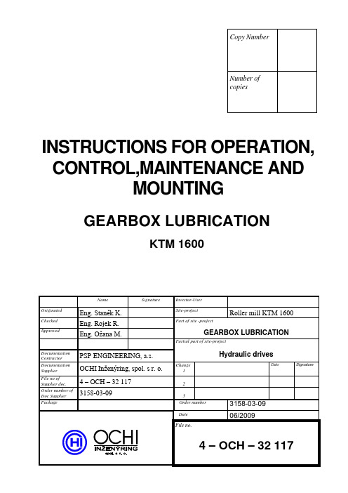
INSTRUCTIONS FOR OPERATION, CONTROL,MAINTENANCE ANDMOUNTINGGEARBOX LUBRICATIONKTM 1600CONTENT0. INTRODUCTION 31. EQUIPMENT DESCRIPTION 3 1.1 Technical parameters 3 1.2 Packaging, transportation, conservation 3 1.3 Mounting 41.4 Documentation 42. DESCRIPTION OF FUNCTION 43. ELECTRIC CONTROL 4 3.1 Electric appliances 43.2 Interlocking, signaling, control 54. PUTTING INTO OPERATION 5 4.1 Oil filling of gearbox 5 4.2 Flushing and testing 5 4.3 Working pressure set up 6 4.4 Flow rate signaling 6 4.5 Pressure control 6 4.6 Oil filtration 6 4.7 Temperature control 64.8 Level control 65. EQUIPMENT OPERATION 66. EQUIPMENT MAINTENANCE 77. SPARE PARTS AND GASKETS 8 7.1 Instructions for spare parts and gaskets ordering 80. INTRODUCTIONWe provide you this accompanying documentation to supplied equipment. You will find technical parameters and instructions for correct putting the equipment into operation, for control and maintenance.1. EQUIPMENT DESCRIPTIONThe equipment consists of the following parts : - aggregate- pipe distributionLubrication aggregate is a source of lubrication oil. It consists of the frame on which lubrication unit is placed (pump and electric motor), filter, cooler, contact thermometer, safety valve and flow rate switch.Pipe distribution is made with the pipes connected with flat flanges and closing valves. Pipe distribution is connected to the gearbox with hoses or rubber compensators for vibration compensation. On the gearbox body there is a level gauge with level switch and ball valve for discharge.Lubrication function is shown on the functional diagram dr.no. 4-OCH-31 011.1.1 Technical parametersLubrication aggregate∙Tank capacity -∙Delivered quantity 43 dm3min-1∙Safety pressure 10 bar∙Max. input 1,5 kW∙Electric motor revolutions 1400 min-1∙Working liquid Mineral oil ISO VG 100 ( according to DIN 51 519 ) ∙Working temperature 20 - 55 °C.∙Filtration rate 25 μm∙Heating In gearbox – 2 x 750 W∙Cooling Water cooler, P CH=18 kWat ∆t=25°C∙Electric motors voltage ~400 V, 50 Hz∙Elements voltage 24 V DC1.2 Packaging, transportation, conservationAll the parts of lubrication system are conserved with the lubrication oil and the parts of pipe distribution and the outlets from the aggregate and separate elements are plugged for transportation. Lubrication aggregate is possible to replace only for the lower part of the frame.1.3 MountingEquipment mounting is performed by the specialists for lubrication equipment or by the staff properly trained. Mounting shall be done in accordance with attached technical documentation.All parts of the pipe distribution shall be properly cleaned prior to mounting.The lubrication aggregate is mounted to the machine prior to the assembly of pipe distribution and is fixed with anchor bolts to the footing. After proper cleaning of the inlets the lubric. aggregate is connected with the gearbox by means of pipe distribution. Connection spots are shown on the lubrication aggregate layout drawing dr.no. 3-OCH-31 128and piping distribution is connected according to the functional diagram dr.no. 4-OCH-31 011.Mounting shall be documented with the assembly book mentioning the firm that performed mounting.1.4 DocumentationThe lubrication aggregate is usually supplied with :∙The instructions for operation, control, maintenance and mounting∙functional diagram∙specification of elements∙layout drawing of lubrication aggregate∙motor list2. DESCRIPTION OF FUNCTIONLubrication liquid is sucked with gear hydrogenerator (pos. 103) from the gearbox housing. Liquid flows further under pressure about 1÷3 bar through double filter (pos. 107) and the cooler (pos. 119) back to the gearbox housing on three lubricated spots. Filter clogging signal is electric.Pressure part of lubrication circuit is secured with pressure about 10 bar by means of pressure valve mounted on gear hydrogenerator (pos. 103).Working pressure is possible to control visually by means of manometer (pos. 109).Flow rate of lubrication oil is controlled with flow rate switch (pos. 114).Liquid temperature in gearbox is remote controlled with temperature sensor (pos. 117).Minimal oil level in the gearbox is signaled with level switch (pos. 122) mounted on gearbox.Remote control of pickup values is terminated on control panel.3. ELECTRIC CONTROL3.1 Electric appliancesPos. 102 - electric motor FCPA 90 L-4, 1,5 kW, 1400 min-1, 400 VPos. 106 - terminal switch DIN EN 50 041 – A1 250 VPos. 107 - filter clogging indicator AE.70.P.-.B, 3 VA, 24 VPos. 114 - flow rate sensor SI5000, 0,4 A, 24 VPos. 117 - temperature sensor T1005, 4÷20 mA, 230 VPos. 119 - water valve AB 21-23 / G3/4-G24 Z4, 12W, 24 VDCPos. 122 - level switch SNK 176 V-C-O-12-R, 0,5A, 24 VPos. 124 - heating element type 14070, 750 W, 230 V3.2 Interlocking, signaling, control-oil level drop in the gearbox below MIN –level switch SL1=0(pos.122) –electric motor run interlock M1 (pos.102) – FAILURE-closed ball valve SQ1=0(pos.106) –electric motor run interlock M1(pos.102) –FAILURE-insufficient lubrication – flow rate switch SQ2=0(pos.114) for a period more than 2 min. – electric motor run interlock M1 (pos.102) – FAILURE-filter clogging SF1=1 (pos.107) – signaling-low oil temperature (<15︒C) – temperature sensor BT1 (pos.117) – electric motor run interlock M1 (pos.102) – FAILURE-high oil temperature (>55︒C) – temperature sensor BT1 (pos.117) – water valve Y1=1 switched (pos.119)-high oil temperature (=60︒C) –temperature sensor BT1(pos.117) - visualization - warning-very high oil temperature (>70︒C) –temperature sensor BT1(pos.117) - electric motor run interlock M1 (pos.102) – FAILURE-oil heating – is automatically on at electric motor start M1 (pos.102) in case that oil temperature in the gearbox BT1 < 25 °C. It is off at BT1 = 35 °C4. PUTTING INTO OPERATIONPutting into operation is performed at the customer after it is connected to the machine lubrication and electric circuit. After transportation it is necessary to check the assembly of the aggregate parts, especially seating of electric motors and pumps.Putting into operation shall be done only by the equipment fabricator or by the persons trained by the fabricator who will be approved by the fabricator in written.During putting into operation the whole course of putting into operation shall be documented in the book. Putting into operation shall be done in accordance with the following points:4.1 Oil filling of gearboxGearbox filling shall be done with filtration filling unit with possibility of filtration min. 25 μm. Prescribed liquid is mentioned in technical parameters p.1.1. Level shall be checked on the level indicator (pos. 122)4.2 Flushing and testingPrior to putting into operation it shall be checked, whether the direction of electric motor turning corresponds to the data on the pump plate, on right-handed pump the direction of turning is in clockwise direction, with a view from electric motor to the pump. Pressure valve is released. Having performed the check, start the pump and let it run without pressure. During commissioning check and refill working fluid.After flushing it is necessary to take off oil sample from the gearbox to estimate liquid purity. If oil meets purity class 9 according to NAS 1638, it is possible to start with the lubrication equipment testing.Flushing shall be done also after long shut-downs and bigger repairs that involve pipe distribution.4.3 Working pressure set upMax. working pressure in lubrication circuit shall be set up by means of safety valve to 10 bar. Pressure is adjusted with the screw turning ( supply – pressure raise).Maximal working pressure can be adjusted at closed closing valve (pos. 120) at the outlet from the lubrication aggregate.4.4 Flow rate signalingFlow rate switch (pos. 114) signals liquid flow rate at the outlet from the aggregate.4.5 Pressure controlPressure can be controlled by means of built-in pressure gauge (pos. 109).4.6 Oil filtrationOil filtration is assured with double outlet filter (pos. 117). Filter is equipped with electric sensor of clogging and by-pass valve in case of clogging. Filtration degree is mentioned in technical parameters.Filtration insert substitution shall be done in case of :- impurity indicator signal (for more than 2 minutes)- after the first 500 hours after putting equipment into operation or once a year (according to the laboratory oil analysis – performs specialized firm ) -oil substitution4.7 Temperature controlOil temperature is measured with temperature sensor (pos. 117). Oil temperature can be checked with thermometer (pos. 118) – only when the pump runs.4.8 Level controlOil level height is controlled with level switch (pos. 122) that sends electrical signal if oil level in the gearbox is minimal and interlocks the drive, when oil level drops below emergency level.5. EQUIPMENT OPERATIONThe equipment operators shall be familiar with:a) the work of lubrication circuit in accordance with the functional diagramb) have basic knowledge about maintenance of lubrication equipmentc) safety rules and principles of safe work during manipulation with mineral oilsd) the function of lubrication elements and the way of their controlThe operators duties are :-performance of preventive examinations of equipment-control of hydraulic elements at adjustment-determination of requirements for equipment maintenance-maintain the book documenting running of the lubrication equipment and performed repairs6. EQUIPMENT MAINTENANCEMaintenance is an important condition for operation of the lubrication equipment. Any interferences for the maintenance of equipment are performed when it is out of operation (without pressure) and by the workers specially assigned for this work who are responsible for this work and properly trained for this activity.A part of the equipment maintenance Is the implementation of so called inspection system, duly documented with the book and checked, in which the following data are especially mentioned :-examination of equipment, in particular connections of pipe distribution-record of finding the first drop or oil leakage and the way of removal-assignment of repair date and responsible worker-confirmation about performance of the repair and its control-parallel oil check performed by specialized firm at least once a month and oil refill, as requiredImplementation of the inspection system is a necessary presumption foreventual claim procedure.Prior to eventual repair all lubrication equipment shall be cleaned in order to prevent from dirty entry into oil during repair. All the repairs are performed when agreed with the equipment operators.Especially for the first 3 months after passing-over the equipment to the User it is necessary to follow-up leaks of the pipe distribution and the connections shall be regularly retightened.At each long equipment shut-down it is useful :-to check the level height, or refill oil (only assigned quality with auxiliary hydrogenerator through the filter 25 m)At each repeated start :-to check oil level-to check filter cloggingFurthermore, during operation it is necessary to follow-up :-operation oil temperature-equipment noise7. SPARE PARTS AND GASKETSFor the equipment it is possible to order from the firm OCHI –INŽENÝRING, s.r.o. any spare parts or gaskets in accordance with the specification of elements dr.no. 4-OCH-31 129.7.1 Instructions for spare parts and gaskets orderingWhen ordering the spare parts you must mention :-production number of aggregate and number of the order as per the plate-date of production-name and marking of the element or the gasket in accordance with the specification of elements-number of pieces。
齿轮箱基础知识培训讲义

技术协议常用知识
• 控制方式:
• 手动:一般采用推拉软绳实现远距离操 纵
• 电控:电磁阀型号:34E2-25BY, DC24V,I=0.94mA
• 气控:操纵空气压力0.5~1.0Mpa
注:电控和ቤተ መጻሕፍቲ ባይዱ控均带机旁应急手动装置
技术协议常用知识
• 仪器、仪表:
2.
FD06、FD16、FD40、J40、
FD120、J120、FD135、FD135A(仅此处
A代表出口用)、J135B、J135、FD300、
J300、D300、T300、J400A、JD400A、
JT400A、J600、JD600、JT600A、
JT600A/1、JT600A/2、JT700/1、
6.输入联轴器部件
齿轮箱输入端采用橡胶高弹联轴节,通过其内 齿圈用螺栓与主机飞轮相连,有与柴油机相配的 SAEJ617C NO.0和NO.1联接罩壳以及与SAEJ620d 16#、18#飞轮相联接的内齿圈可供用户选用。高弹 联轴器能有效减小和吸收震动,提高传递能力,延 长使用寿命。
7.冷却器部件
要求冷却水进水温度不大于32度,冷却水的流 向应与压力油的流向相反,以提高冷却效果。当环 境温度低于0度,齿轮箱不工作时,应将冷却水放 净。
NBC5700 (垂直异心)
PMG540 (水平异心)
NBC6000B (偏心)
YBF10-1470 (一进多出)
四 扭振计算需要参数
• 船舶参数: 船名、 船型、总长、总吨、设计、制造、 船东;
• 扭振减振器参数(若有,装在柴油机上): 型号、扭转刚度、阻尼(非硅油减振器)、 转动惯量(硅油减振器:减振器惯性轮和 壳体的转动惯量);
齿轮箱部分培训教材
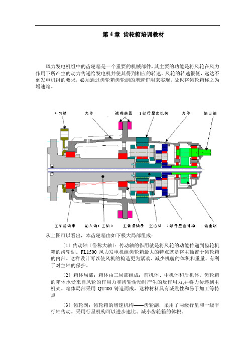
第4章齿轮箱培训教材风力发电机组中的齿轮箱是一个重要的机械部件,其主要的功能是将风轮在风力作用下所产生的动力传递给发电机并使其得到相应的转速。
风轮的转速很低,远达不到发电机组的要求,必须通过齿轮箱齿轮副的增速作用来实现,故也将齿轮箱称之为增速箱。
从上图可以看出,本齿轮箱由如下极大局部组成:〔1〕传动轴〔俗称大轴〕:传动轴的作用就是将风轮的动能传递到齿轮机箱的齿轮副。
FL1500风力发电机组齿轮箱最大的特点就是将主轴置于齿轮箱的内部。
这样设计可以使风机的构造更为紧凑、减少机舱的体积和重量、有利于对主轴的保护。
〔2〕箱体局部:箱体由三局部组成:前机体、中机体和后机体。
齿轮箱的箱体承受来自风轮的作用力和齿轮传动时产生的反作用力,并将力传递到主机架。
箱体局部采用QT400铸造而成,这种材料具有减震性和易于加工等特点〔3〕齿轮副:齿轮箱的增速机构——齿轮副,采用了两级行星和一级平行轴传动。
采用行星机构可以进步速比、减小齿轮箱的体积。
驱动端输出端从上图可知,齿轮箱主轴的前端法兰与风轮相连,风作用到叶片上驱动风轮旋转,风轮带动齿轮箱主轴旋转,从而主轴带动后面的增速机构开场运转。
这样齿轮箱就把风轮所吸收的低转速、大扭矩的机械能转化成高转速、小扭矩的机械能传递到齿轮箱的输出轴上。
齿轮箱的输出轴通过弹性联轴器与电机轴相连,驱动发电机的转子旋转,将能量输入给发电机。
发电机将输入的动能转化成电能并输送到电网上。
齿轮箱通过加紧法兰和楔块被固定到主机架上。
在齿轮箱与于加紧法兰、齿轮箱与主机架之间均有减噪板弹簧。
这使齿轮箱和主机架之间没有任何的刚性连接。
这种方式可以最大程度上吸收齿轮箱所产生的震动,减小振动对主机架的影响。
在齿轮箱的前端设有转子锁定装置,当对系统进展检修时可以通过此装置锁定风轮,确保风力发电机处于平安状态。
如下列图所示,当需要所定风轮时,用手将在齿轮箱的前部和后局部别设有三个加热器。
当齿轮箱工作环境温度较低时,为确保齿轮箱内部的光滑油保持在一定的粘度范围,可使用加热器对齿轮箱光滑油进展加热。
ZF-Duoplan 双速齿轮箱 2K450 2K600 操作手册说明书

ZF 股份公司版权所有 ©本文件受版权保护。
未经 ZF 股份公司许可不得对本文件的全部或摘选内容进行违法复制和传播。
违法行为将受到民事和刑事处罚。
本文件为德文原件的翻译版本。
操作手册2K450/2K600 目录1 前言 (5)1.1 安全规范 (5)1.2 ZF 规范 (5)1.3 消耗品 (6)2 应用与设计 (7)2.1 应用 (7)2.2 特点 (7)2.3 设计 (8)2.4 技术资料 (9)2.5 安装位置 (10)3 初次安装 (11)3.1 驱动电机径向跳动、轴向跳动和 长度公差 (11)3.2 动平衡 (12)3.2.1 半键动平衡 (12)3.2.2 全键动平衡 (12)3.3 电机与齿轮箱的配合 (13)3.3.1 开放式设计 (13)3.3.2 封闭式设计附轮毂轴承与轴封 (14)3.3.3 封闭式设计(附轴封) (15)3.3.4 开放式设计附接合环 (16)3.3.5 皮带轮驱动设计 (17)3.4 齿轮箱的安装 (18)3.5 输出 (19)3.5.1 皮带式输出 (19)3.5.2 轴式输出 (19)3.5.3 不带输出 (19)3.6 电气接线与换档 (19)3.6.1 换档机构 (19)3.6.2 换档逻辑 (22)3.7 润滑 (23)3.7.1 泼溅式润滑 (23)3.7.2 循环式润滑 (23)3.7.3 循环润滑的连接口 (25)ZH 4161.758.926c – 2015-10 3操作手册目录2K450/2K6004 运转 (28)4.1 运转前检查 (28)4.2 太阳轮安装位置检查 (28)5 保养 (28)5.1 换油 (28)6 维修 (29)6.1 齿轮箱故障检查表 (29)6.2 齿轮箱的分离 (30)6.3 轮毂 (30)7 常见问题与解决 (31)4 ZH 4161.758.926c – 2015-10操作手册2K450/2K600前言ZH 4161.758.926c – 2015-10 51 前言本手册专为有修理和维护经验的专业人士 提供。
- 1、下载文档前请自行甄别文档内容的完整性,平台不提供额外的编辑、内容补充、找答案等附加服务。
- 2、"仅部分预览"的文档,不可在线预览部分如存在完整性等问题,可反馈申请退款(可完整预览的文档不适用该条件!)。
- 3、如文档侵犯您的权益,请联系客服反馈,我们会尽快为您处理(人工客服工作时间:9:00-18:30)。
4.2 圆柱齿轮计算 关闭输出界面,选择“Detailing” “Machine elements”,显示出机械元件选择 框,点击齿轮对“Gear pair”.
通过数据窗口的显示,可以选择齿轮箱中的任一对齿轮。在此,选齿轮对 “Radpaar_01”分析,选择并点击“OK”按钮确定。弹出一个描述齿轮对剖面相关信息 的对话框。选择“Advanced parameters of the chosen variant” “Machine elements” “spur gears”下的 Reference profile 选定相关剖面 。这种情况下,也可以选择首 次输入。
在装配菜单,可以定义转速和转矩是否可计算。如下图选择
例子中,驱动转矩和转速是设定好的。所以选择默认值。转速前的数学符号可 以改变旋转防线,转矩必须要大于 0,X-offset 值必须是 30mm
在“Welle_02”右边定位输出,这时要设定转矩和转速状态为可计算。X-position 为 360mm。至此就完成了教程的图形输入部分。 按上面步骤,可得到如下一个齿轮箱。
这段轴是实体轴,所以内径为 0。第一段轴要通过快速端面定位空间位置,点 击 objects operation 里的 Move objects 按钮,按下鼠标拖动,可以看到快速定位表 面显示黄色,移动轴段,靠近黑色十字,当快速定位层颜色变蓝,松开鼠标, 轴与黑十字联在一起,就定义好了轴的空间位置 再加两段轴,将新加轴联靠在第一段轴的右边并输入如下参数:
轴的结果三维图看起来应如下
点击轴的进一步参数输入“Advanced parameters shaft”栏的十字按钮,离开细节 输入模式 4.4 轴承计算 选择进入“Choice bearing”,开始轴承“Lager_01”计算。 标注轴承的具体要求,Gearbox 通过内部数据库,会建议合适的轴承。对于这 个例子,可选择标准设置。在轴承参数“Bearing parameters”栏,可通过图形界面选 择轴承类型。点击“Tapered roller bearing”.
“Choice of elements for the calculation”选择所有元件“All elements”.
你可以得到一个所有计算结果的全览。
5.工程数据的保存 所有的这个计算的计算数据都被保存在一个工程文件夹。 在你的 PC 机上的初始文件夹时临时的。 建立一个新的计算文件, 临时夹里的数 据将会清除。所以直接选择一个新的保存地址很重要。假如你先做了计算,就要将 数据复制到新地址。 如下图选择一个地址并点击“yes”确认。然后再一次保存工程。通过接下来的软 件使用,所有数据将被重新保存。
建模开始前, 返回到输入界面。 在材料栏, 可通过这两个表格输入选定齿轮和轴的材料,
点 击 表 格 右 上 的 数 据 库 选 择 按 钮 , 可 以 选 择 数 据 来 源 , MDSIGN-database 或 者 user-database。
显示出一个标准材料菜单, 齿轮选择材料 16MnCr5, 轴选择材料 16MnCr5 和 E295。
如上方法建模另一个轴承,定位到另一边,X-offset 值为 379mm。 现在需要为轴“Welle_02”建模两个轴承,这两轴承有不同规格。
第二个轴上也要端面承压轴承。所以轴承类型也像前两个一样,X-offset 分别为 20mm 和 214mm
3.4 输入和输出建模 元件部分基本都装完了,定义好载荷就可以开始计算。在元件浏览框 “Force elements” “Drive”选择并放在第一根轴上,先是为一个绿色箭头
材料和润滑如前。移动齿轮可以看到齿轮和轴上都有一条黄色的快速定位线,移 动齿轮直到黄线变蓝松开鼠标,将齿轮定位到轴“Welle_01”
两元件可绕旋转轴旋转,但是 X 方向坐标是一定的。所以选择齿轮并确定 x 方向 值为 275,x 方向偏移量是指轴原点到齿轮中点的距离。
X-offset 值为 106mm 选择组建(“Welle_02” 和 “Rad_02”),按下 Alt-button 和鼠标,不要松开,否着 将断开齿轮和轴的联系,在两轴中间各有一条黄色快速定位线,移动组建直到两线
如下图,以毫米单位尺寸建模第二根轴。
第二段轴“Welle_02”可以放在屏幕的任意位置。在连接直齿轮时,定义这段轴 的空间位置。从左至右的构造轴可以更加容易的定位直齿轮。第二段轴的材料 E295. 3.2 直齿轮设计 直齿轮建模很容易。在元件浏览框“Gear” “Spur gear” “External gear”选 择并拖出一个三维模型,选择并指定斜角。
用户得到一个完整的最优化的齿轮箱模型, 并基于精确建模的基础上研究所有机械 元件的灵敏度。
打开 MDESIGN 右边的菜单文件夹 MDESIGN gearbox 双击进入. 点击 data→new→ reset开始一个新的工程.所有输入界面数据将被重置. 选择”choice calculation”→”calculation”. 将数据保存为后缀(*.xml)文件存入新文件夹。 你就可以对这组数据进行操作修改。
4.1 动力学计算 回到输入界面,从下拉菜单选择(the entry calculation)进入计算。软件提供三 种可用的计算,可以在“choice of level of detail of the gearbox”栏或者工具条 actions 中选择
材料栏下,加载数据,安全性,使用寿命都显示了数据。其他大多数值也已经 通过图形输入设置过了。唯一的报警数据是 “Advanced parameters of the chosen variant” “Joints” “Gear pairs”栏里的齿效。设置齿效值为 0.99。不需要更多 的输入,按 F10,开始计算 屏幕右边会给出输出界面。 其中包括了扭矩, 转速, 能量, 传动比等计算结果。 在“Document”栏可以整理输出结果。 输入和计算数据将列成一个清单, 编辑成 HTML, RTF,PDF 格式文本。文本语言可以选择
现在进入图形输入界面,选择下拉菜单。
图形输入工作条显示在工作框上面
图形输入有着不同的输入方法。坐标系统在工作框中间,是齿轮箱的设计区。左边菜单 时元件浏览框,可供选择你所需要的机械元件,左边菜单显示你所选择元件的属性。 底部时图形和文档帮助, 操作上手方便。 工作条上右边是对象操作 (objects operation) 按纽, 你可以由此选择零件并 3 维视角移动。 左边部分是模型选择对象 (model/select object) 按钮,由此可以详细说明零件的具体信息。
MDSIGN gearbox 模块推出了多级直齿和行星齿轮设计布局,这是 DriveConcepts 公司一项 全新发展.首先,用户得以有一个强大的设计工具,可以快速直观的进行齿轮箱的设计,接着又 能根据实际工程标准对齿轮箱各元件再计算 可帮助齿轮设计过程
在“再计算”模式下,必须选择一个优化方案。将自动对所有机械元件,如轴,轴 承和啮合等,进行应力地址
工程夹里的计算数据
“Choice of level of detail of the gearbox” “Choice of elements for the calculation” 下点击“User function”确定,也可以用工作条。
现在可以改变齿的参数。首先设置中心距 “Centre distance”为 218mm。“Input method topland shortening”栏下拉菜单选择“No input”。如果这些系数都设为 0,工 程将按标准方法计算。在下一行(基于 DIN3992/3993 标准齿顶面修形)(“Addendum modification according to DIN 3992/3993”)再次选择输入方法为“No input”并优化“平 衡齿” (“Balanced toothing”) 。按 F10 计算,几秒就可以计算出轴承的安全性.如果安 全系数比要求低,输出也上部会以红色字体给出警报. 另外,可以看所有的计算步骤,在图像菜单,可以看到齿轮的不同图形,而且这些图 形都可以容易的备份保存,如齿轮剖面图,点蚀和点蚀轴承允许值图形
变蓝,就连接上了两个齿轮,
3.3 轴承建模 图形输入模式下,能够直接定义轴承规格,后面可能还有特别说明。如前定位 轴承并定义参数如下图
轴承类型可通过图形选择按钮。 在弹出窗口选择左边已安装好的轴承的类型图。 轴承同样需要选择润滑油。 像齿轮一样,轴承也是靠快速定位线定位,X-offset 值为 171mm。
可以通过点击鼠标“Strg”和左键选择整段轴。
可通过中键移动组件组合体计连着的坐标系统,还可以滚动中键缩放。选定整 轴后,可选定轴的材料。点击 model / select object 栏 Selection 并在属性里标记输入 材料。就可以选择一个定义好的材料。 “ Welle_01”是一个斜角轴,所以需选材料 16MnCr5. 双击,可进入 2 维轴的计算编辑页面。这里可以添加和移除轴段以及外加载荷和 槽口。
通过表格顶部的图形帮助按钮,可检查所有参数是否正确。右边的图形应显示 为一个带扭矩,轴承和键槽的 3 维轴 。点击按钮 F10 开始计算。
输出界面显示设计的最终安全系数和中间变量值,可整理为文档文件
另外,图形输出可显示转矩,应力和弯曲程度等曲线图,例如:
“Welle_02”的计算,在如下表格中选择两个槽口的数据输入
如果齿轮箱要求得是一个特殊轴承,就需要标注输入轴承参数, 这个例子不需 要。按 F10 开始计算。
一个符合工作寿命要求的 tapered roller bearing 表格如下,选择 32316A 轴承 输出页上将显示一个符合寿命要求的轴承,也有所选轴承的参数
重复上述过程选择其它轴承。选择轴承类型如下: Lager_02:Tapered roller bearing-32316A Lager_03:Tapered roller bearing-30224A Lager_04:Tapered roller bearing-33024 现在,你已经建造了一个完整的齿轮箱,具体要求也详细输入了。但是,这个 例子只是给你一个粗略的齿轮箱设计,好让你理解使用这个模块设计齿轮箱的每一 个步骤。 4.5 所有元件的计算 所有机械零件都详细说明了,你可以对所有零件进行计算。在计算元件的选择