压力释放阀说明书中英
压力释放阀说明书[中英]
![压力释放阀说明书[中英]](https://img.taocdn.com/s3/m/2e96aecc76c66137ef06192d.png)
压力释放阀PRESSURE RELEASE VALVE使用说明书OPERATION INSTRUCTION明远电器设备SHENYANG MINGYUAN ELECTRIC EQUIPMENT CO., Ltd.本说明书适用于我公司生产的系列变压器用压力释放阀,阐述其用途、性能、规格、技术参数、使用及安装,供用户参考。
The Operation Instruction is applicable to pressure release valve of a series of transformers manufactured by our company, indicating its application, performances, specifications, technical parameters, usage and installation for uses’ reference.1. 压力释放阀用途和性能压力释放阀适用于油浸式电力变压器、电力电容器及有载分接开关等,用来保护油箱。
当油浸式变压器在运行中出现故障时,由于线圈过热,使一部分变压器油汽化,变压器油箱中压力迅速增加,这时压力释放阀在2ms迅速动作,释放压力,保护油箱不致变形或爆裂。
油箱的压力再升高而达到开启压力时,压力释放阀应再次动作,直到油箱的压力降到正常值。
由于压力释放阀动作后能可靠关闭,油箱外的水和空气不能进入油箱,变压器部不会受大气污染。
1.Application and performancePressure release valves play a vital role in the protection of oil-immersed electrical equipments, such as transformers, high voltage switch gears, capacitor and on load tap-changers, etc. This device can prevent the oil-immersed electrical equipment from deformation or rupture. Should a fault occur in such electrical equipment, from deformation of rupture? Should a fault occurring in such electrical equipment, they are instantaneously vaporize the oil causing extremely rapid build-up of gaseous pressure? If mounting this type pressure release device on the oil-tank, when the pressure reaches to its opening pressure, it opens automatically within 2ms and relieves the pressure.2.型号、规格及基本参数Type, specification and technical parameters2.1 型号的含义 Meaning of typeY S F□—□ / □□□特殊环境代号(Special environment)带机械信号标“J”(“J”:mechanical signal)带信号开关标“K”(“K”:electrical signal)两者都带标“KJ”(“KJ”:Both with signal)喷油有效口径(Caliber of oil-gushing tube)mm开启压力(Opening pressure)kPa设计序号(Design serial number)阀(valve)释放(release)压力(pressure)注:特殊环境代号 note: special environment:TA: 干热带地区 dry tropicTH: 湿热带地区 humid tropicT: 干、湿热带地区 dry、humid tropic例:YSF16-55/130KKJT开启压力为55kPa,喷油口径为φ130mm,带电信号、机械信号。
Marsh Hawk TRV 1系列4000压力释放阀说明书

v e n t i n g| g a u g e h atc h e sS E R I E S4000 M A R S H H AW K T RVFeatures• Premium deep-set gauge hatch with integral pressure & vacuum relief offers superior performance in normal and cold conditions.• reliable, bubble-tight sealing with standard Fkm ( viton) seal and stainless steel spring.• Field adjustable pressure settings, from 2 ozsi to 32 ozsi.• manual relief, inconel trim, alternative seals and various coatings optionally available.F E AT U RE SDeep-set venting gauge hatch• the series 4000 marsh hawk trv offers tank access combined with pressure and vacuum reliefin a deep-set design.• situating valve seats below the tank roof permits latent heat from the product to keep the seals ice-free.Reliable, bubble-tight sealing• the series 4000 has class-leading sealperformance as compared to any other premium or economy venting gauge hatch currently available.• improved sealing performance eliminates flutter and periodic small-scale venting which can cause frost closure in competitor top-mount hatches.Variety of pressure settings• the series 4000 marsh hawk pressure relief is adjustable between 2 ozsi and 16 ozsi in 2 ozsi increments.• the optional double-weight spring allows relief pressure between 18 and 32 ozsi, in 2 ozsiincrements.• 1 ozsi increments optionally available.• vacuum relief is fixed at 0.4 ozsi.Suitable for Sour Service• the series 4000 is ready for sour service out of the box with Fkm ( viton) seals and stainlesssprings.• For more adverse applications, alternative seal and spring materials are available, along withhard anodization or fusion-bond epoxy coatings.S P E C I F I C AT I O NS¹temperatures provided are continuous service temperatures for the indicated seal materials. see the short term extended service temperatures below in “seal materials and configuration” section.D I M E N S I O NSFalse-colour cutaway of a series 4000 marsh hawk trv showing the deep-set seal (orange), pressure spacers(blue) and springs (red).F LOW C H A R AC T E R I S T I C-3.2-3-2.8-2.6-2.4-2.2-2-1.8-1.6-1.4-1.2-1-0.8-0.6-0.4-0.20T A N K V A C U U M , V (O Z S I )024681012141618202224262830323436384042444648505254565860626401234567891011121314151617181920212223242526272829303132333435T A N K P R E S S U R E , P (O Z S I )FL OW RA T E T H R O UG H M A R S H H AW K, Q , X 1000 SCF H (AIR)O P T I O N S A N D AC C E S S O R I E SManual Reliefthe manual relief option allows an operator to manu-ally activate the vent.Pressing the hatch cover’s large red button on the actu-ates the vacuum pallet, relieving pressure in the tank to allow safe removal of the spider cage assembly for tank gauging or hatch maintenance. the button and actuating poppet are supported independently of the vacuum disc, and do not interfere with normal relieving operation.Hard Anodized (Type III)For situations requiring improved corrosion resistance over the standard marsh hawk, a hard anodization option is available. this electrochemical process in-creases the thickness and durability of the ceramic-like natural aluminum oxide layer.all aluminum components are anodized to meet miL-a-862F type iii engineering hardcoat. the anodization slightly darkens the cast components and imparts a slight bronze tinge to the machined components.anodization improved performance in moderate brines, as well as acetic, boric and nitric acid. For prolonged exposure to concentrated brines, or strong mineral acids, consider the severe service coating.Severe Service CoatingFor situations demanding the highest corrosion resis-tance, consider the severe service coating.the body of the marsh hawk is coated with a red Fusion Bond epoxy (FBe) for resistance to mineral acids,(including sulphuric and hydrochloric acids up to 15%) high-chloride ion solutions (including alumi-num chloride, potassium chloride and brine) as well as many other petrochemicals.the marsh hawk internals are coated in a proprietary black PFa (teFLOn) providing the same excellent fluo-ropolymer chemical resistance as the FBe above.series 4000 marsh hawk trv with manual relief Optionseries 4000 marsh hawk trv with hard anodizationseries 4000 marsh hawk trv with severe service coatingO P T I O N S A N D AC C E S S O R I E S (C O N T I N U E D )S E A L C O N F I G U R AT I O N A N D M AT E R I A L S the series 4000 marsh hawk combines the pressure and vacuum valve in an innovative design that requires only one shared gasket.to improve valve sealing performance, gaskets are factory coated with a pliable silane-based sealant. an optional oil-based sealant for use in sour gas applica-tions is also available. Both sealants are available in small packages for maintenance and reapplication.hawkeye offers three material options for the pressure / vacuum seal, beyond the standard Fkm (viton®) seal.• For applications where sealing is the first priority and the vent is not expected to operate often and has low set pressures (under 4 ozsi), eFkm (sponge viton®) can be supplied.• For higher temperature, minimally freezing conditions and acid service FePm (aflas®) is available.• For extreme applications FFkm (kalrez®) is also available.the use of ePDm seals in any hawkeye vent is contra-indicated due to its unsuitability in common petrochem-ical applications.hawkeye does not offer or recommend using solid fluoropolymer (PtFe, PFa, FeP, etc.), nor expanded flu-ropolymer (gOre-tex®) as a gasket material and any venting device. although the material may be chemi-cally suitable, the harder crystalline polymer structure of these materials impedes sealing at the typically low interfacial pressures found in the marsh hawk, as well as other low-pressure (i.e. <15 psi) vents.GENE R A L FLU OROEL A STOM E R CHEM ICA L C OM PATI BI LI T Y¹FKM / VI TON N.B.¹ THIS CHART I S F OR R EFE REN CE ONLY. ALT HOUG H HAWKEYE STRI VES TO E NSU RE P RE SE NTE D I NF OR MATI ON I S ACCURATE, A QUALIF I ED PE RSON SHO ULD EN SURE TH E SUI TABILI T YO F A S E LECTED MATER IA L I N T HE SPECIF IC CHEMI CAL, TEMP ERATURE A ND PRE SSU RE C O NTE XT O F TH EI R APPLI CATIO N.² SH OWN F OR COMPA RI SON PURPOSE S ON LY, NOT AVA ILABLE AS A SEAL M ATE RIAL O N H AW KE YE VE N TS60330OPE R AT I NG TE M PE R ATU R E , °CNOR MA L RAN G EVITON IDHOLE AFLAS IDHOLES KALREZ ID HOLESID E N T IF Y IN G M AR S H H AWK GAS K E T M AT E R I A LMesh Hata formed 10 mesh 304 stainless steel cover to keep insects and debris from interfering with the marsh hawk internals.De-icing Systemallows direct injection of a seal-appropriate de-icing solution onto the marsh hawk internals from ground level. includes spray nozzle and hose assembly.PA RTS L I S T&M AT E R I A L S O F C O N S T R U C T I ONPAC K AG I N Gseries 4000 marsh hawks are shipped complete and boxed. in addition to the marsh hawk itself,the car-ton contains bolt kit(s), tank gasket(s) and installation instructions.weight is approximately 28 lb [12.7 kg].P R E S S U R E T E S T I N G series 4000 marsh hawks are tested prior to packaging to ensure pressure-tightness and relief setting accuracy. items passing the quality control measures are marked with the label at right.•P A S S•P R E SS UR E T ES T E DV E N T M A R K I N Gthe spider cage assembly of the series 4000 marsh hawk is tagged with the initial factory confi guration of the valve. as the relief pressure is fi eld-adjustable, space is left on the tag to record future set pressures,should they change.C E RT I F I C AT I O Nthe pressure and vacuum relief settings of the series 4000 marsh hawk can be factory certifi ed at an addi-tional expense. certifi ed hatches are accompanied by a certifi cate stating the relief pressure of the hatches.R I S E RS & S P O O L SBolt-on risers account for the slope of the tank roof ensuring the series 4000 marsh hawk sits level for trouble-free operation. adapter spools allow installa-tion of a marsh hawk or other 8” aPi 12B/F device onto an ansi B16.5 fl at-face fl ange or other aPi man-way or tank opening. see the “risers, spools & rings” brochure for more information. 12:1 Bolt-on Hatch Riserthe most popular riser used with the series 4000 marsh hawk, the HRSP-0800, ensures a vertical gauge hatch orientation on a 12:1 sloped tank roof with an existing 8” aPi 12B/F fl at-face connection.[in.][mm.]rh riser height (max) 4.2107rcmin minimum fl ange gap2.563.5P Pitch12:1 4.8°rd Outisde Diameter 12.0305riinside Diameter8.0203the series 4000 marsh hawk is just one part of tank-age product lines from hawkeye industries, that also includes:Vapor Controlseries 5000 ePrv series 6000 Pvrv Mechanical Level Indicationmodel 1000 Redtail & model 1500 Roadside Dry seal Zero emission Level gauging systems model 2000 Goshawk Level transmitter for Dry seal Zero emission Level gauging systemsR E L AT E D P R O D U C TScontents © 2006 - 2021 hawkeye industries inc. this document is uncontrolled, and is subject to change without notice. Please refer to for the most up-to-date product information. 2110 70 ave nwedmonton, aB, canada t6P 1n6toll Free: (800) 910-4295Phone: (780) 490-4295Fax: (780) venting - series 4000 marsh hawk trv 01Jun2021Printed in canada.O R D E R I N G I N F O R M AT I O Nstandard series 4000 marsh hawk configurations are stocked ready to ship. Other configurations are typically assemble-to-order and available in under two weeks. configure your desired series 4000 marsh hawk trv us-ing the part number legend below. items in bold are standard items and have fastest lead times. all series 4000 marsh hawks ship complete with a gr. 5 Bolt kit and cr (neoprene) Base gasket, both upgradable (see below). For project quantities, contact your hawkeye sales rep for delivery schedules.Relief & MaterialOptionsMHMSMesh ScreenMHKD De-icing System0000Accessories Base GasketBolting KitSeries 6000 PVRV。
压力释放阀使用说明书(沈阳金钟)

YSF压力释放阀YSF Pressure release valve使用说明书Instructions沈阳市金钟电器厂Shenyang Jinzhong electrical appliance factoryYSF Pressure release valve带防护罩的YSF4,5型压力释放阀定向喷油螺纹安装的YSF6型压力释放阀With a protective hood Specify the direction of Spray oil , Thread Installed定向喷油法兰安装的YSF7型压力释放阀定向导油法兰安装的YSF8,9型压力释放阀Specify the direction of Spray oil , Flange Installation Specify the direction of Oil Guide,Flange Installation YSF7 Pressure release valve YSF8,9 Pressure release valve- 1 -二, 型号、规格与基本技术参数Models, specifications and basic technical parameters:1, 型号Model :Y S F / D(S)KJTHB压力释放阀Pressure release valve 型号举例Model example: YSF 5 –55 / 130 D(S)KJTHBYSF 代表压力释放阀, 5 代表设计序号, 55 代表开启压力, 130 代表有效口径,YSF On behalf of pressure release valve,5 Serial number of Design,55 Opening pressure,130 Effective aperture D ( S ) 代表开关数量单( 双 ), K 代表电信号, J 代表机械信号, TH 代表湿热带地区,B 代表闭锁装置 D(S) -Switch amount one(two), K -Electric Signal, J - Mechanical signal, TH -Humid Tropics, B-Locking Device 2, 使用条件:-30℃至+100℃ 如遇寒带地区,采用特殊密封圈可满足-45℃Exploitation conditions -30℃ to +100℃ In case the frigid zone area, uses the special seal packing collar to be possible to satisfy -45℃3, 基本技术参数Basic technical parameters :有效口径Effective aperture (mm) 开启压力Opening pressure(KPa)关闭压力(不小于)Close Pressure (Not less than)(KPa)∮25∮5015±58 25 13.5 35 19 55 29.5 ∮80 ∮1303519 55 29.5 70 37.5 85 45.5 13874.5三, 带有电信号的输出接线线路图With electrical signal output wiring circuit diagram:a, 单开关接线线路图 b, 双开关接线线路图 C,双开关接线线路图Single-switch Two-switch Two-switch wiring circuit diagram wiring circuit diagram wiring circuit diagram信号开关接点容量Signal switch contact capacity :AC 220V 5A DC 220V 0.3A(电阻负载Resistive load )- 2 -。
压力放流3口阀门与锁定孔商品说明书

Doc. No. VH*-OMX0068-APressure Relief 3 Port Valve with Locking HolesVHS20-(F,N)01~(F,N)02(-R,Z)-DVHS30-(F,N)02~(F,N)03(-R,Z)-DVHS40-(F,N)02~(F,N)04(-R,Z)-DPage 1. Safety Instructions 1~52. Application 63. Specifications 64. How to Order 7~85. Construction / Parts List 96. Dimensions10with Locking Holes Safety InstructionsThese safety instructions are intended to prevent hazardous situations and/or equipment damage.These instructions indicate the level of potential hazard with the labels of “Caution,” “Warning” or “Danger.”They are all important notes for safety and must be followed in addition to International Standards (ISO/IEC)*1) , and other safety regulations.*1) ISO 4414: Pneumatic fluid power -- General rules relating to systems. ISO 4413: Hydraulic fluid power -- General rules relating to systems.IEC 60204-1: Safety of machinery -- Electrical equipment of machines .(Part 1: General requirements)ISO 10218: Manipulating industrial robots -Safety. etc.Caution Caution indicates a hazard with a low level of risk which, if not avoided, could resultin minor or moderate injury.Warning Warning indicates a hazard with a medium level of risk which, if not avoided, could result in death or serious injury.DangerDanger indicates a hazard with a high level of risk which, if not avoided, will resultin death or serious injury.Warning 1. The compatibility of the product is the responsibility of the person who designs theequipment or decides its specifications.Since the product specified here is used under various operating conditions, its compatibility with specific equipment must be decided by the person who designs the equipment or decides its specifications based on necessary analysis and test results.The expected performance and safety assurance of the equipment will be the responsibility of the person who has determined its compatibility with the product.This person should also continuously review all specifications of the product referring to its latest catalog information, with a view to giving due consideration to any possibility of equipment failure when configuring the equipment.2. Only personnel with appropriate training should operate machinery and equipment.The product specified here may become unsafe if handled incorrectly.The assembly, operation and maintenance of machines or equipment including our products must be performed by an operator who is appropriately trained and experienced.3. Do not service or attempt to remove product and machinery/equipment until safety is confirmed.1.The inspection and maintenance of machinery/equipment should only be performed after measures to prevent falling or runaway of the driven objects have been confirmed.2.When the product is to be removed, confirm that the safety measures as mentioned above are implemented and the power from any appropriate source is cut, and read and understand the specific product precautions of all relevant products carefully.3. Before machinery/equipment is restarted, take measures to prevent unexpected operation and malfunction.4. Contact SMC beforehand and take special consideration of safety measures if the product is to be used in any of the following conditions.1. Conditions and environments outside of the given specifications, or use outdoors or in a place exposed to direct sunlight.2. Installation on equipment in conjunction with atomic energy, railways, air navigation, space, shipping, vehicles, military, medical treatment, combustion and recreation, or equipment in contact with food and beverages, emergency stop circuits, clutch and brake circuits in press applications, safety equipment or other applications unsuitable for the standard specifications described in the product catalog.3. An application which could have negative effects on people, property, or animals requiring special safety analysis.e in an interlock circuit, which requires the provision of double interlock for possible failure by using a mechanical protective function, and periodical checks to confirm proper operation.with Locking HolesSafety InstructionsCautionThe product is provided for use in manufacturing industries.The product herein described is basically provided for peaceful use in manufacturing industries.If considering using the product in other industries, consult SMC beforehand and exchange specifications ora contract if necessary.If anything is unclear, contact your nearest sales branch.Limited warranty and Disclaimer/Compliance RequirementsThe product used is subject to the following “Limited warranty and Disclaimer” and “Compliance Requirements”. Read and accept them before using the product.Limited warranty and Disclaimer1.The warranty period of the product is 1 year in service or 1.5 years after the product is delivered,whichever is first.∗2)Also, the product may have specified durability, running distance or replacement parts. Please consult your nearest sales branch.2. For any failure or damage reported within the warranty period which is clearly our responsibility,a replacement product or necessary parts will be provided.This limited warranty applies only to our product independently, and not to any other damage incurred due to the failure of the product.3. Prior to using SMC products, please read and understand the warranty terms and disclaimersnoted in the specified catalog for the particular products.∗2) Vacuum pads are excluded from this 1 year warranty.A vacuum pad is a consumable part, so it is warranted for a year after it is delivered.Also, even within the warranty period, the wear of a product due to the use of the vacuumpad or failure due to the deterioration of rubber material are not covered by the limitedwarranty.Compliance Requirements1. The use of SMC products with production equipment for the manufacture of weapons of massdestruction(WMD) or any other weapon is strictly prohibited.2. The exports of SMC products or technology from one country to another are governed by therelevant security laws and regulation of the countries involved in the transaction. Prior to the shipment of a SMC product to another country, assure that all local rules governing that export are known and followed.CautionSMC products are not intended for use as instruments for legal metrology.Measurement instruments that SMC manufactures or sells have not been qualified by type approval tests relevant to the metrology (measurement) laws of each country.Therefore, SMC products cannot be used for business or certification ordained by the metrology (measurement) laws of each country.Warning1. Please consult with SMC if the intended application calls for absolutely zero leakage due tospecial atmospheric requirement, or if the use of a fluid other than air is required.2. Do not apply negative pressure, as may cause malfunction.3. Do not supply air pressure from ports other than the 1(P) port, as may cause malfunction.4. When lockout is to be used, recommend using a lock with a shackle diameter of φ5 or more.Less than φ5 is to be used, please test it on the actual machine.Warning1. In some cases, mineral oil grease used for internal parts and sealant may be carried todownstream side. Please consult with SMC if this causes any inconvenience in use.Warning1. Do not drop or apply impact during transportation or installation, as may cause breakageor malfunction.2. Do not install in locations of high humidity or high temperature. Operation outside of theproduct specification range may cause breakage, malfunction, or shorten life performance.3. Connect the product ensuring the direction of "1"(IN) and "2"(OUT) for air direction andindicated arrow. Reverse connection may cause malfunction.Caution4. The valve must be switched to each position instantly and securely. Stopping the handlebetween the extreme positions may cause malfunction.Warning1. Before piping is connected, it should be thoroughly blown out with air (flushing) or washed to remove chips, cutting oil and other debris from inside. Should they remain, they could cause malfunction.2. When screwing piping or fittings into ports, ensure that chips from the pipe threads or sealing material do not enter the piping. Also, if sealant tape is used, leave 1.5 to 2 thread ridges exposed at the end of threads.3. When screwing piping into a component, hold female threaded side and apply the recommended tightening torque. Insufficient tightening torque may cause loosening or sealing failure and excess tightening torque may cause damage to threads. Tightening without holding female threaded side, excess force is applied to the bracket directly, and may cause breakage.4. Do not apply torsion or bending moment other than the product's own weight. Support external piping separately as it may cause breakage. Non-flexible piping, such as steel tube piping, are prone to be affected by excess moment load or vibration. Use flexible piping in between to avoid such affects.5. For piping into the exhaust port, it is recommended to use a resin silencers (AN series). After tightening the silencer by hand, use a suitable wrench on the hexagonal flats to tighten an additional 1/4 turn. When installing one-touch fittings (KQ2 series) or the piping, add 1/2 turn after tightening by hand. Excess tightening torque may cause damage to threads.Warning1. Use clean air. Do not use compressed air which contains chemicals, organic solvent, synthetic oil or corrosive gas, etc., as it may cause breakage or malfunction.2. Install an air dryer or after cooler on upstream side. Air containing excess drainage may cause malfunction.Caution3. Install an air filter of 5 µm filtration on upstream side.4. Install a mist separator on upstream side to remove carbon powder from the compressor or other equipment. Excess carbon dust may cause malfunction.Refer to SMC’s “Air Cleaning Equipment” catalog for further details on compressed air quality.Recommended tightening torque Unit: N-m Thread size 1/8 1/4 3/8 1/2Torque 7 to 912 to 1422 to 2428 to 30Warning1. Do not use in atmospheres contacting corrosive gases, chemicals, sea water, water,water steam, or where there is direct contact with any of these.2. Do not use in explosive atmosphere.3. Do not use in locations subject to vibration or impact.4. Do not expose to direct sunlight for an extended period of time. Protective cover should beused to shield.5. Do not mound in locations where is nearby heat source. Radiated heat should be alsoprevented.6. Implement suitable protective measures in locations where there is contact withwater droplets, oil, or welding spatter.7. Install a silencer into exhaust port to prevent the dust ingress if there is a lot of dust inatmosphere, as dust may cause air leakage.Warning1. When equipment is to be removed, first confirm that measures are in place to preventworkpieces from dropping, run-away of equipment, etc.. Then cut off the supply air pressure and electric power, and exhaust all compressed air from the system using its residual pressure release function.When the equipment is to be restarted after remounting or replacement, first confirm that measures are in place to prevent lurching of actuators and then confirm that equipment operates normally.2. Do not disassemble. Improper handling may cause malfunction or breakage of themachinery or equipment.2. ApplicationsThis product is a residual pressure release valve which is switched by hand.3. Specifications(1) Standard specifications (2) Flow characteristics-6- Model VHS20VHS30 VHS40FluidAirAmbient and fluid temperature -5 to 60o C (No freezing)Proof pressure1.5MPa Maximum operating pressure 1.0MPa Handle operation Switching angle 90o Rotating torque Note1)0.8N-m or less 1.0N-m or less 3.0N-m or less Weight95g 181g400gNote 1) Supply pressure: 1.0 MPaModelPort size Supply (IN →OUT) Exhaust (OUT →EXH) IN, OUT EXH C(dm 3/s-bar)b Cv C(dm 3/s-bar)b Cv VHS201/8 1/84.0 0.41 1.1 3.7 0.42 1.1 1/45.8 0.31 1.4 3.8 0.42 1.1 VHS30 1/4 1/48.8 0.44 2.4 8.0 0.46 2.3 3/8 14.1 0.28 3.5 7.8 0.46 2.2 VHS401/43/8 9.5 0.49 2.8 13.3 0.47 3.6 3/8 17.2 0.47 4.8 13.6 0.47 3.7 1/226.70.296.313.40.433.74. How to Order- - - VHS 30 03 D❶❷❸❹# A spacer or spacer with bracket is required if the valve is combined with modular F.R.L. Please order it separately.VHS type can be ordered from How to Order of modular F.R.L. combination.Spacer (Y □-D)Spacer with bracket(Y □T-D)Pressure relief 3 port valve Spacer part no. Spacer with bracketpart no. Applicable F.R.L. combinationVHS20 Y200-D Y200T-D AC20-D VHS30 Y300-D Y300T-D AC30-D VHS40Y400-DY400T-DAC40-D* New VHS series compatible with previous model spacer Y200(T)-A to Y400(T)-A.Pressure relief 3 port valve5. Construction/ Parts list-9-No.DescriptionStandard specificationsMaterial Note 1 Body ADC12 White 2 Body cover POM White 3 Handle POM Red 4 Bonnet PBT- 5Valve guideFlame resistant PBT (UL94 standard V-0 equivalent )White 6 Cam ring POM - 7 Sleeve POM - 8 Spool PBT - 9 O-ring H-NBR - 10Spring Stainless steel-# The VHS series cannot be disassembled. Parts cannot be shipped separately.6. Dimensions-10-Model Standard specifications P1 P2 A B C D E F G H VHS20 1/8, 1/4 1/8 71.5 23 40 37 28 42 17.5 40 VHS30 1/4, 3/8 1/4 873253 49 38 53 20 53 VHS401/4, 3/8, 1/23/8111 42.3706352712970Padlock mounting position(Port size)(Port size)Rev. A - Safety Instructions (Piping) corrected.- How to Order added *2 and *3.4-14-1, Sotokanda, Chiyoda-ku, Tokyo 101-0021 JAPANTel: + 81 3 5207 8249 Fax: +81 3 5298 5362© 2019 SMC Corporation All Rights Reserved。
万花器公司的比例压力释放阀说明书

Wandfluh AG Tel. +41 33 672 72 72 E-mail: ******************Illustrations not obligatoryData sheet no.PostfachFax +41 33 672 72 12 Internet: Data subject to change 2.3-562E 1/4 CH-3714 Frutigen Edition 17 01TYPE CODEB D IPM22 --/ M E-#Pressure relief valve Direct operated Proportional, inverse Screw-in cartridge M22x1,5Nominal pressure rang p N 20 bar 20 200 bar 200 100 bar 100 315 bar 315160 bar 160 350 bar 350Nominal voltage U N 12 VDC G1224 VDCG24Slip-on coilMetal housing, square Execution connectionIntegrated electronicsHardware configurationWith analog signal (0…+10 V factory set)A1With CANopen acc. to DSP-408C1With Profibus DP in accordance Fluid Power Technology P1With CAN J1939 (on request) J1Function AmplifierController with current feedback signal (0...20 mA / 4...20 mA) R1Controller with voltage feedback signal (0...10 V) R2Sealing material NBRFKM (Vitron)D1Design-Index (Subject to change)Proportional pressure relief valve inverse Screw-in cartridge• Integrated amplifier or controller electronics • Direct operated• Q max = 20 and 25 l/min • p max = 400 bar • p N max = 350 barDESCRIPTIONDirect operated proportional pressure relief valve with integrated electronics and inverse function. Thread M22x1,5 for cavity according to ISO 7789. These plug & play valves are factory set and adjusted. High valve-to-valve reproducibility. Housing for electronics with protection class IP67 for harsh environment. As standard versions, 6 pressure ranges are available: 20, 40, 63, 100, 160, 200, 315 and 350 bar. Good flow performance due to the differential area principle. Small leakage along the poppet guide. Adjustment by a Wandfluh (VDE-Norm 0580) proportional solenoid. The cartridge and the solenoid made of steel are zinc coated and therefore rust-protected.FUNCTIONThe valve limits the pressure in the port P (1) and reliefs the volume flow to tank port T (2). The back pressure in T (2) influences the pressure in P (1). The reliefed pressure drops with rising solenoid current (inverse function), and the with deenergised solenoid, a maximum pressure is present. The control connection is provided by an analog interface or a fieldbus interface (CANopen or Profibus DP). Parameter setting and diagnosis with the free-of-charge software «PASO» or via fieldbus interface. After taking off the cover of the electronic housing, the serial interface to adjust the settings is accessible. The menu controlled Windows program «PASO» allows easy adjustment of all variable settings. Data are stored in a non-volatile memory. Even after an electric power failure settings can easily be reproduced and transmitted.APPLICATIONProportional pressure relief valves with inte-grated electronics are well suited for demanding applications, in which the pres-sure frequently has to be changed. They are implemented in systems calling for good valve-to-valve reproducibility, easy installati-on, comfortable operation and high precision in industrial hydraulics as well as in mobile hydraulics. The proportional pressure relief catridge is very suitable for mounting in control blocks, flange bodies and sandwich plates size NG4-Mini and NG6. (Please note the separate data sheets in register 2.3). Cavity tools are available for machining the cavities in steel and aluminium (hire or purchase). Please refer to the data sheets in register 2.13.M22x1,5ISO 7789Wandfluh AG Tel. +41 33 672 72 72 E-mail: ******************Illustrations not obligatory Data sheet no.Postfach Fax +41 33 672 72 12 Internet: Data subject to change 2.3-562E 2/4CH-3714 FrutigenEdition 17 01SYMBOL37s3M22x1.5T(2)X1X2X4 (nur Regler)(controller only)35.583X1X3X225,30501821, 2240706s613M DELECTRICAL SPECIFICATIONSProtection class IP 67 acc. to EN 60 529with suitable connector and closedelectronics housingSupply voltageRampsParameterisationInterfaceAnalog interface:Mating connectorPreset value signalFieldbus interface:Device receptaclesupply (male)Mating connectorDevice receptacleCANopen (male)Mating connectorDevice receptacleProfibus (female)Mating connectorPreset value signalFeedback signal interface (Sensor):(controller only)Device receptacle (female) M12, 5-polesMating connector Plug (male), M12, 5-poles(not incl. in delivery)Feedback signal:: Voltage / current state when orderingCONNECTOR WIRING DIAGRAMAnalog interface:Supply voltage +Supply voltage 0 VDCStabilised output voltagePreset value voltage +Preset value voltage -Preset value current +Preset value current -Reserved for extensionsReserved for extensionsEnable control (Digital input)Preset value voltage (PIN 4/5) resp. current (PIN 6/7) are selected withV), (PIN 4/5)Parameterisation interface (USB, Mini B) X2Under the closing screw of the housing coverFeedback signal interface (Sensor)Device receptacle (female) X4 (only controller)1 = Supply voltage (output) +2 = Feedback signal +3 = Supply voltage 0 VDC4 = not connected5 = stab. output voltage2 = Reserved for extensionsDevice receptacle Device receptacleCANopen (male) X3 Profibus (female) X3CAN PROFIBUS1 = not connected 1 = VP2 = not connected 2 = RxD / TxD - N3 = CAN Gnd 3 = DGND4 = CAN High 4 = RxD / TxD - P5 = CAN Low 5 = Shield31452123543145212354123451234123431452HYDRAULIC SPECIFICATIONSFluid Mineral oil, other fluids on requestContamination ISO 4406:1999, class 18/16/13efficiency (Required filtration grade ß 6…10≥75)see data sheet 1.0-50/2Viscosity range 12 mm2/s…320 mm2/sFluid temperature -20…+70°CPeak pressure pmax= 400 barNominal pres. ranges pN= 20 bar, 100 bar, 160 bar, 200 bar,315 bar, 350 barMin. volume flow Qmin= 0,1 l/minMax. volume flow Qmax= 25 l/min for pN=20 bar / 100 bar /160 bar / 200 barQmax= 20 l/min for pN= 315 barQmax= 5 l/min for pN= 350 barLeakage volume flow see characteristicsRepeatability ≤ 3 %Hysteresis ≤ 5 %GENERAL SPECIFICATIONSDescription Direct operated proportional pressure reliefvalve with integrated electronics inverse functionConstruction Screw-in cartridge for cavity acc. to ISO 7789Operations Proportional solenoid wet pin push type,pressure tightMounting Screw-in thread M22x1,5Ambient temperature -20…+65°C (typical)(The upper temperature limit is a guideline value for typicalapplications, in individual cases it may also be higher or lower.The electronics of the valve limit the power in case of a toohigh electronics temperature. More detailed information can beobtained from the operating instructions «DSV».)Mounting position any, preferably horizontalFastening torque MD= 50 Nm for screw-in cartridgeMD= 5 Nm for knurled nutWeight m = 1,0 kgWandfluh AG Tel. +41 33 672 72 72E-mail: ******************Illustrations not obligatoryData sheet no.PostfachFax +41 33 672 72 12 Internet: Data subject to change 2.3-562E 3/4 CH-3714 FrutigenEdition 17 01CHARACTERISTICS Oil viscosity υ = 30 mm 2/s p = f (Q) Pressure volume flow characteristics (Maximum adjustable pressure)p= f (Q) Pressure volume flow characteristics (Minimum adjustable pressure)Q L = f (p)Leakage volume flow characteristicsp red = f (l) Pressure adjustment characteristics[at Q = 10 l/min] / (s corresponds to preset value signal)p = f (l) Pressure adjustment characteristics [at Q = 5 l/min] /(s corresponds to preset value signal)NOTE!Detailed electrical characteristics and description of «DSV » electronics are shown on data sheet 1.13-76.START-UPFor DSV amplifiers as a rule no parameter settings by the customer are required. The plugs have to be connected in accordance with the chapter «Pin assignment».Controllers are supplied configured as amplifiers. The setting of the mode of control and the setting of the controller are done by the customer by software setting (USB interface, Mini B).Additional information can be found on our website:«»Free-of-charge download of the «PASO»-software and the instruction manual for the «DSV » hydraulic valves as well as the operation instruc-tion CANopen eg.Profibus DP protocol with device profile DSP-408 for «DSV ».NOTE!The mating connectors and the cable to adjust are settings is not part of the delivery. Refer to chapter «Accessories».Factory settings:Dither set for optimal hysteresis= Deadband: Solenoid switched offwith command preset value signal <5 % p Nmechanicallly pre-set at Q = 5 l/min= Limited pressure in port P (1) at 70 % of preset value signal: 95 bar with pressure range 350 bar 65 bar with pressure range 315 bar 56 bar with pressure range 200 bar 32 bar with pressure range 160 bar 25 bar with pressure range 100 bar 4 bar with pressure range 20 bar0 10 20 30 40 50 60 70 80 90 100s [%]p [bar]4003002001000 10 20 30 40 50 60 70 80 90 100s [%]p [bar]1209060300p = f (l) Pressure adjustment characteristics [at Q = 5 l/min] / (s corresponds to preset value signal)40030020010000 5 10 15 20 25Q [l/min]p [bar]N = 200 bar N = 160 bar N = 100 bar N= 20 bar504030201000 5 10 15 20 25Q [l/min]403020100 50 100 150 200 250 300 350 p [bar]Q [cm 3/min]0 10 20 30 40 50 60 70 80 90 1001251007550250I [%]p [%]Wandfluh AG Tel. +41 33 672 72 72 E-mail: ******************Illustrations not obligatoryData sheet no.PostfachFax +41 33 672 72 12 Internet: Data subject to change 2.3-562E 4/4 CH-3714 Frutigen Edition 17 01Cavity drawing according to ISO 7789–22–02–0–98For detailed cavity drawing and cavity toolssee data sheet 2.13-1003With fieldbus interface Amplifier With fieldbus interface ControllerDIMENSIONS / SECTIONAL DRAWINGS*Adjusting screw for setting the nominal pressure (-20 % / +30 %)With analog interface Amplifier and ControllerACCESSORIES • Cartridge built in:flange and sandwich bodies see register 2.3• Set-up softwaresee start-up• Cable to adjust the settings through interface USB (from plug type A to Mini B, 3 m) article no. 219.2896• Cable connector for analog interface: – straight, soldering contact article no. 219.2330 – 90°, soldering contact article no. 219.2331Recommended cable size: – Outer diameter 9…10,5 mm – Single wire max. 1 mm 2 – Recommended wire size: 0…25 m = 0,75 mm 2 (AWG18) 25…50 m = 1 mm 2 (AWG17)Technical explanation see data sheet 1.0-100PARTS LIST Position Article Description17160.2187O-ring ID 18,72 x 2,62 (NBR)18160.2170O-ring ID 17,17 x 1,78 (NBR)20154.2700Knurled nut21223.1317Dummy plug M16 x1,522160.6131O-ring ID 13,00 x1,525062.0102Cover square 30072.0021Gasket 33,2 x 59,9 x 240208.0100Socket head cap screw M4 x1050160.2188160.6188O-ring ID 18,77 x 1,78 (NBR)O-ring ID 18,77 x 1,78 (FKM)60160.2140160.6141O-ring ID 14,00 x 1,78 (NBR)O-ring ID 14,00 x 1,78 (FKM)70049.3177Back-up ring RD 14,6 x 17,5 x 1,4353790.2s 30M 22x 1.5T(2)X2X1X3X4172.4P(1).5(1)E: Venting。
YSF6型系列压力释放阀说明书
技术支持:024-89378958 89368080
网 址:
E-mail:sales@
service@
4
_____________________________________________________________________________________
沈阳沈变所电气科技有限公司(原沈阳变压器研究所实验厂)
公司地址:沈阳浑南新区世纪路 39 号
邮 编:110179
销售热线:024-89368025 传 真:024-89368108
1
结构及安装尺寸
(a)YSF6Ⅱ型不带开关外形及结构图
(b)YSF6Ⅱ型带开关外形及结构图
(c)YSF6Ⅲ-/25 型压力释放阀外形及结构图
产品外形及安装尺寸
(d)YSF6-/25 型压力释放阀外形及结构图
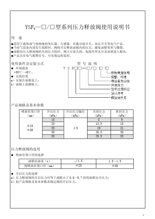
有效喷油口径 (mm)
Φ25(a,b,c 型) Φ25(d 型) Φ50(a,b 型)
D1 (mm) Φ40 Φ40 Φ67
密封压力 (kPa)
9 15 21 30 33
压力释放阀的选用
● 喷油有效口径的选择 油箱内油重(t)
阀喷油有效口径(mm)
∠1.5 Φ25
1.5~4.5 Φ50
● 开启压力的选择 a)压力释放阀的开启压力应等于或略小于 0.6~0.7 倍的油箱安全压力; b)按产品规格及基本参数表确定阀的开启压力。
重要提示
●闭锁装置应在变压器运行前拆除,确保压力释放阀的正常运行。 ●安装时压力释放阀各零、部件不可随意拆卸。 ●设备运行时,如释放阀开启使标志杆跳起,在查明原因后将标志杆手动复位,解除
报警。
维护与检修
利用电气设备每次停电检修的机会对压力释放阀进行下列检修: ●开启动作是否灵敏,如有卡堵现象应排除。 ●密封胶圈是否已老化、变形或损坏。 ●零部件是否变形或损坏。 ●信号开关动作是否灵活。
Armstrong Delta2 - DRP SERIES 自动压力减小 释放控制阀门说明说明书

DRP SELF REGULA TING SERIESDRP Series - Control ValvesProduct FeaturesArmstrong Delta2 - DRP SERIES is a globe self actuated pressure reducing/relief Control Valve for a wide range of process applications.• available size from DN15 to DN100 and from 1/2" to 4".• available pressure rating DIN from PN10 to PN40.• available pressure rating ANSI from 150lbs to 300lbs.MaterialsFull range of materials and special alloys are available for valve body and trim including hardening treatment. Special NACE design andmaterial construction for Sour Service with a Compliance Declaration in accordance to NACE regulations. GuidingValve guiding is top for standard disk plug and is made directly on plug shaft to guarantee a larger guiding and plug stability for accurate control application.TrimStandard construction includes disk plug and threaded replaceable seat.Stem SealStandard stem seal for DRP - Pressure Reducing valves up to 50 barg is full Stainless Steel Bellow seal for zero leakage in case of Higher class or Pressure Relief applications a Standard Low Emission packing and the integral diaphragm is used.SPECIAL DESIGNDRP Series - Control Valves Standard Part List1918DRP Series - Control ValvesFunctioning of pressure reducing valves on steamSteam enters through port 1 (valve is normally open but flow direction close the plug), flowing through seat 2 and plug 3 and reduces its pressure moving out through port 4.The piping 5 connect the condensation pot 6 with the control area 7 andtransmits the variation of reduced pressure at the bottom of Diaphragm 8.Example given is supposing that the reduced pressure exceeds thevalue of valve spring range setted up.Then the control spring 9 will be compressed by the higher force present in the control area 7 and therefore the plug will close slicely to valveseat causing an higher pressure drop that in a short time will results in a downstream pressure balanced according to the spring set range.In fact an opposite action happens when the downstreampressuretend to decrease: the pressure of controlarea 7 decreases, allowing to control spring 9 tomove the plug in opening direction and therefore the downstream pressure will be re-established.The value of reduced pressure can be change by operating on thespring range setting with the apposite key.(1)ANSI / ISA 75.08.01 or ISA S75.03 on request(2) Special high capacity trim are available on request.(3) Standard rangeability 30:1. Optional higher rangeabilities can be provided.Valve SpecificationValve ConnectionsStandard Facing according to EN 1092-1 Form B1 up to PN40 and Form B2 above.Standard Facing according to ASME B16.5 Form RF (Ra 125-250 AARH Smooth Finish).Materials of Construction(1)= Special materials available on request.Materials of ConstructionPressure and Temperature Ratings(*)= Maximum allowable temperature of Gases without Condensation Pot is 120°C.Pressure and Temperature CurvesFlow Coefficient TableOptions:- Full Hard Facing through Overlaying or Treatments available for all Port Size. Actuators Down Pressure Range Table113/8"Designs, materials, weights and performance ratings are approximate and subject to change without notice.Visit armstrong for up-to-date information.North America • Latin America • India • Europe / Middle East / Africa • China • Pacific Rimarmstrong international.euValve Dimensions1) DIN PN10 to PN40 Face to Face lenght according to EN 558-1 serie 1, DIN 3202 F1 (ANSI/ISA 75.08.01 on request)Actuators Dimensions 1) ED = Envelope Diameter is the minimum horizontal space necessary for valve maintenence.2) EH = Envelope Height is the minimum vertical space necessary for valve maintenence.Condensate Pot DimensionsValve Condensate PotActuatorINTELLIGENT SOLUTIONS IN STEAM, AIR, AND HOT WATERarmstrong international.eu。
CROSBY 800和900 OMNI-TRIM 系列压力释放阀 安装及维修说明书

CROSBY 800 和 900 OMNI-TRIM ® 系列压力释放阀安装及维修说明书1概述Crosby 阀门已在出厂前进行了测试和调整。
当使用条件有变化时可能还需要作少量的调整。
只要遵循本文的指示,进行调整是很容易的。
警示为达到无故障运行,应确保在安装阀门前彻底清洁阀门的进口和出口。
2存放和搬运阀门在安装之前通常会在工作现场保存几个月。
如果存放和防护不当,阀门性能可能造成不利影响。
粗鲁的搬运和污物可能损伤阀门或造成阀门零件的对正性。
建议将阀门留在原包装箱内,并存放在仓库里,或者至少要放置在干燥的表面并加防护罩,直到阀门使用。
压力释放阀必须小心搬运,不得遭受剧烈冲击载荷。
它们不应遭受冲击、颠簸和坠落。
粗鲁的搬运可能改变阀门的整定压力,使阀门零件变形,从而对阀门密封和性能造成不利的影响。
注对于配有D 型和E 型保护罩的带扳手阀门,不可利用扳手来提升或搬运阀门。
在阀门准备好进行系统安装之前,不应去掉阀门进口和出口的防护罩盖。
警示确保材料及产品对买方预期用途的适应性是买方的责任。
储藏、安装和适当的使用也是买方自己的责任。
Emerson 不承担由此产生的任何和所有责任。
注意生命和财产安全常常有赖于压力释放阀的正常工作。
因此,阀门应保持清洁并应定期进行测试和检修,以确保压力释放阀正常的工作。
工程文档编号IS-V3117对压力释放阀的任何安装、维护、调整、修理和测试按相关规范和标准的要求进行。
按照这些要求执行此类工作的人员应从相应的管理机构得到适当的授权。
任何由本公司之外人员进行的修理、装配和测试工作均不在本公司对用户担保的范围内。
你对你的工作承担全部责任。
在维修本公司产品时,应当只使用本公司制造的零件。
如果需要现场协助,请联系离您最近的Emerson 区域销售办公室或代表。
目录1. 概述 ...............................................................12. 存放和搬运 ...................................................13. 安装 ...............................................................24. 试验 ...............................................................35. 整定压力 .......................................................36. 维修-解体......................................................37. 清洁 ...............................................................48. 密封面研磨-仅对金属密封阀门...................49. 维修-装配......................................................410. 保护罩和提升扳手的装配 ............................511. 更换用备件 (6)800系列螺纹连接铅封O 型圈O 型圈软密封金属对金属密封阀座固定螺钉阀杆保护罩调整螺杆调节螺栓螺母上弹簧座弹簧下弹簧座阀瓣座导向套固定螺钉垫片阀瓣调节圈阀体罩盖弹簧垫片(顶部)调节螺栓主轴900系列螺纹连接调节螺栓螺母阀芯基座气缸阀板固定器密封件和线材O 形圈引导O 形环柔性阀座金属对金属阀座弹簧弹簧垫片(底部)3安装• 进口管道压力释放阀应以垂直向上的位置直接安装于压力容器的接管嘴上,或安装于容器的短的连接附件上。
- 1、下载文档前请自行甄别文档内容的完整性,平台不提供额外的编辑、内容补充、找答案等附加服务。
- 2、"仅部分预览"的文档,不可在线预览部分如存在完整性等问题,可反馈申请退款(可完整预览的文档不适用该条件!)。
- 3、如文档侵犯您的权益,请联系客服反馈,我们会尽快为您处理(人工客服工作时间:9:00-18:30)。
压力释放阀适用于油浸式电力变压器、电力电容器及有载分接开关等,用来保护油箱。
当油浸式变压器在运行中出现故障时,由于线圈过热,使一部分变压器油汽化,变压器油箱中压力迅速增加,这时压力释放阀在2ms内迅速动作,释放压力,保护油箱不致变形或爆裂。油箱内的压力再升高而达到开启压力时,压力释放阀应再次动作,直到油箱内的压力降到正常值。由于压力释放阀动作后能可靠关闭,油箱外的水和空气不能进入油箱,变压器内部不会受大气污染。
The Operation Instruction is applicable to pressure release valve of a series of transformers manufactured by our company, indicating its application, performances, specifications, technical parameters, usage and installation for uses’ reference.
阀(valve)
释放(release)
压力(pressure)
注:特殊环境代号note: special environment:
TA: 干热带地区dry tropic
TH: 湿热带地区 humid tropic
T: 干、湿热带地区dry、humid tropic
例:YSF16-55/130KKJT开启压力为55kPa,喷油口径为φ130mm,带电信号、机械信号。适用于干、湿热带地区的压力释放阀。
1.Application andperformance
Pressure release valves play avital role in the protection of oil-immersed electrical equipments, such as transformers, high voltage switch gears, capacitor and on load tap-changers, etc. This device can prevent the oil-immersed electrical equipment from deformation or rupture. Should a fault occur in such electrical equipment, from deformation of rupture?Should a fault occurring in such electrical equipment, they are instantaneously vaporize the oil causing extremelyrapid build-up of gaseous pressure?If mounting this type pressure release device on the oil-tank, when the pressure reaches to its opening pressure, it opens automatically within 2ms and relieves the pressure.
Example: YSF16-55/130KKJTin which, opening pressure is 55kPa,caliber of oil-gushing tube isφ130mmand flange erection, with electrical and mechanical signal and waterproof, use in dry、humid tropic。
带信号开关标“K”(“K”:electrical signal)
两者都带标“KJ”(“KJ”:Both withsignal)
喷油有效口径(Caliber of oil-gushing tube)mm
开启压力(Opening pressure)kPa
设计序号(Design serial number)
表2 单位:kPa Table Ⅱ unit:kPa
开启压力
opening pressure
15
25
35
55
70
85
开启压力偏差
deviation of openingpressure
±5
关闭压力≥
closing pressure
8
13.5
19
29.5
37.5
45.5
密封压力≥
seal pressure
2.2 规格(见表1)Specifications(given in Table Ⅰ)
表1Table Ⅰ
喷油有效口径
effective caliber(mm)
开启压力
opening pressure(Kpa)
φ20
15,25,35,55
φ25
φ50
φ80
35,55,70,85
φ130
2.3 基本参数(见表2)Basic technical data(given in Table Ⅱ)
9
21
33
42
51
3.安装尺寸Installation dimensions
3.1 法兰安装尺寸(见表3)Flange installation dimensions(given in Table Ⅲ)
2.型号、规格及基本参数Type,specification and technicalparameters
2.1 型号的含义Meaning of type
Y S F□ — □ / □ □ □
特殊环境代号(Special environment)
带机械信号标“J”(“J”:mechanical signal)
压力释放阀说明书中英
压 力 释 放 阀
PRESSURE RELEASE VALVE
使 用 说 明 书
OPERATIONINSTRUCTION
沈阳明远电器设备有限公司
SHENYANG MINGYUAN ELECTRIC EQUIPMENT CO.,Ltd.
本说明书适用于我公司生产的系列变压器用压力释放阀,阐述其用途、性能、规格、技术参数、使用及安装,供用户参考。