MAX811TEUS-T_电压检测器
高精度电压电流检测模块产品说明书

高精度电压电流检测模块产品说明书CAN PMU连接示意图软件设置ArduPilot 固件(飞行控制器的固件)PX4固件(飞行控制器的固件)在Mission planner 的全部参数表设置以下参数并在写入后重启:在QGroundControl 参数列表中设置以下参数并在写入后重启:CAN_P1_DRIVER=1CAN_P2_DRIVER=1BATT_MONITOR=8(如果使用监视器1)Uavcan_enble 设置为sensors Automatic config(自动配置)注意:请使用AC3.6/AP3.9(含)以上版本的固件注意:PX4固件在1.10或更高版本中支持UAVCAN电源检测模块规格参数基本参数处理器输入电压最大电流电压准确度*电流准确度分辨率STM32F412 100Mhz 512K Flash 256K RAM 6-62V(2-15S)110A±0.05V±0.1A0.01A/V6000W/90S 5000W 5.4V/5A UAVCAN -20℃ ~ +100℃支持工厂校准,用户无需校准最大输出功率最大稳定输出功率稳压输出(Power)通信协议工作温度固件升级校准设置IN/OUTPowerXT90(线材端)/Amass 8.0(模块端)5025850670接口类型尺寸重量CAN PMU 电调连接线X7系列飞控电源线v5系列飞控电源线Pixhawk 飞控连接线X1X1X1X1产品外观46.5mm×38.5mm×22.5mm 76g 配件清单- 请仔细阅读产品的使用说明书- 连接电池前,请仔细检查连线- 请在额定的电压、电流、功率下使用- 请阅读文档中心进行配置和使用- 严禁自行拆装固件升级教程请访问CUAV 文档中心: 注意事项固件升级关于产品的更多信息,请访问CUAV 官方文档中心: 及官方网站:更多资料Thank you for choosing CAN PMU ! CAN PMU interface definition Please read this guide before using!Battery + Battery -ESC + ESC -Status lightCAN PMU connection schematic diagram 5V +5V +C A N _H C A N _L G N D G N D 5T R D I C GCAN PMU connection schematic diagramSoftware settingsArduPilot firmware (flight controller firmware)Set the following parameters in the Mission planner's full parameter list and restart after writing:CAN_P1_DRIVER=1CAN_P2_DRIVER=1BATT_MONITOR=8 (If using monitor 1)Note: Please use the firmware of AC3.6/AP3.9 (included) or higher.PX4 firmware (flight controller firmware)Set the following parameters in the QGroundControl parameter list and restart after writing:Uavcan_enble set to sensors Automatic configNote: PX4 firmware supports UAVCAN power detection module in 1.10 or higher.Specifications Basic parametersProcessor Voltage input Max current Voltage accuracy Current accuracy Resolution STM32F412 100Mhz 512K Flash 256K RAM 6-62V(2-15S)110A±0.05V±0.1A0.01A/V6000W/90S 5000W 5.4V/5A UAVCAN -20℃ ~ +100℃Support No need Max output powerMax stable powerPower port outputprotocolOperating tempFirmware upgradeCalibrationIN/OUTPowerXT90(Cable end)/Amass 8.0(Module end)5025850670Interface TypeSizeWeightCAN PMUX7 series power cableV5 Series Power Cable X1X1X1Appearance46.5mm×38.5mm×22.5mm 76g Packing ListNotes- Please read the product manual carefully.- Please check the connection carefully before connecting the battery- Please use at rated voltage, current and power- Please read the documentation center for configuration and use- Do not disassembleFirmware upgradePlease visit the CUAV Documentation Center for a firmware upgrade tutorial: More infoFor more information on the product, please visit the CUAV Official Documentation Center:And official website:。
华为客户可靠性检验测试规范标准

1测试标准框架 (15)1.1整体框架 (15)1.2测试样品数 (15)1.3不同工艺测试项选择 (18)2外观等级面划分 (18)2.1外观等级面定义 (18)3测量条件及环境的要求 (19)3.1距离 (19)3.2时间 (19)3.3位置 (19)3.4照明 (19)3.5环境 (19)4表面处理可靠性测试方法 (19)4.1膜厚测试 (19)4.1.1试验目的 (19)4.1.2试验条件 (19)4.1.3合格判据 (19)4.2抗MEK(丁酮)测试 (19)4.2.1试验目的 (19)4.2.2试验条件 (20)4.2.3程序 (20)4.2.4合格判据 (20)4.3附着力测试 (20)4.3.1试验目的 (20)4.3.2试验条件 (21)4.3.3程序 (21)4.3.4合格判据 (22)4.3.5等级描述说明 (22)4.3.6测试工具 (23)4.4RCA纸带耐磨测试 (23)4.4.1试验目的 (23)4.4.3程序 (24)4.4.4合格判据 (24)4.5酒精摩擦测试 (24)4.5.1试验目的 (24)4.5.2试验条件 (24)4.5.3程序 (24)4.5.4合格判据 (25)4.6橡皮摩擦测试 (25)4.6.1试验目的 (25)4.6.2试验条件 (25)4.6.3程序 (25)4.6.4合格判据 (25)4.7振动摩擦测试 (26)4.7.1试验目的 (26)4.7.2试验条件 (26)4.7.3程序 (26)4.7.4合格判据 (27)4.7.5说明 (28)4.8铅笔硬度测试 (28)4.8.1试验目的 (28)4.8.2试验条件 (28)4.8.3程序 (28)4.8.4合格判据 (30)4.8.5测试工具 (30)4.9抗脏污测试 (30)4.9.1试验目的 (30)4.9.2试验条件 (30)4.9.3程序 (31)4.9.4合格判据 (31)4.10牛顿笔测试 (31)4.10.1试验目的 (31)4.10.2试验条件 (31)4.10.3程序 (31)4.10.5说明 (31)4.11显微维氏硬度测试 (32)4.11.1试验目的 (32)4.11.2试验条件 (32)4.11.3程序 (32)4.11.4合格判据 (32)4.12耐化妆品测试 (32)4.12.1试验目的 (32)4.12.2试验条件 (32)4.12.3程序 (33)4.12.4合格判据 (33)4.13耐手汗测试 (33)4.13.1试验目的 (33)4.13.2试验条件 (33)4.13.3程序 (33)4.13.4合格判据 (34)4.13.5说明 (34)4.14低温存储 (34)4.14.1试验目的 (34)4.14.2试验条件 (34)4.14.3程序 (34)4.14.4合格判据 (35)4.15高温存储 (35)4.15.1试验目的 (35)4.15.2试验条件 (35)4.15.3程序 (35)4.15.4合格判据 (35)4.16交变湿热 (35)4.16.1试验目的 (35)4.16.2试验条件 (35)4.16.3程序 (36)4.16.4合格判据 (36)4.17温度冲击 (36)4.17.2试验条件 (36)4.17.3程序 (36)4.17.4合格判据 (36)4.18太阳辐射 (37)4.18.1试验目的 (37)4.18.2试验条件 (37)4.18.3程序 (37)4.18.4合格判据 (37)4.18.5说明 (37)4.19盐雾测试 (38)4.19.1试验目的 (38)4.19.2试验条件 (38)4.19.3程序 (38)4.19.4合格判据 (39)4.20水煮测试 (40)4.20.1试验目的 (40)4.20.2试验条件 (40)4.20.3程序 (40)4.20.4合格判据 (40)4.20.5说明 (40)4.21切片测试 (40)4.21.1试验目的 (40)4.21.2试验条件 (41)4.21.3程序 (41)4.21.4合格判据 (42)4.22内部件附着力测试 (42)4.22.1试验目的 (42)4.22.2试验条件 (42)4.22.3程序 (43)4.22.4合格判据 (43)4.23内部件交变湿热 (43)4.23.1试验目的 (43)4.23.2试验条件 (43)4.23.4合格判据 (43)4.23.5说明 (43)4.24内部件温度冲击 (43)4.24.1试验目的 (43)4.24.2试验条件 (43)4.24.3程序 (44)4.24.4合格判据 (44)4.25内部五金件阻抗测试 (44)4.25.1试验目的 (44)4.25.2试验条件 (44)4.25.3程序 (44)4.25.4合格判据 (44)4.26内部五金件高温高湿 (45)4.26.1试验目的 (45)4.26.2试验条件 (45)4.26.3程序 (45)4.26.4合格判据 (46)4.27钢丝绒测试 (46)4.27.1试验目的 (46)4.27.2试验条件 (46)4.27.3程序 (46)4.27.4合格判据 (46)4.283D涂层及小部件验证策略 (46)4.28.13D涂层 (46)4.28.2小部件 (46)5结构件强度测试方法 (47)5.1强度测试位置识别方法 (47)5.1.1试验目的 (47)5.1.2试验条件 (47)5.2落锤测试 (48)5.2.1试验目的 (48)5.2.2试验条件 (48)5.2.3程序 (49)5.3弯折测试 (50)5.3.1试验目的 (50)5.3.2试验条件 (50)5.3.3程序 (52)5.3.4合格判据 (52)5.4拉力测试 (53)5.4.1试验目的 (53)5.4.2试验条件 (53)5.4.3程序 (54)5.4.4合格判据 (54)5.5NMT粘合质量初判 (54)5.5.1试验目的 (54)5.5.2试验条件 (54)5.5.3程序 (54)5.5.4合格判据 (55)5.6NMT剪切强度测试 (56)5.6.1试验目的 (56)5.6.2试验条件 (56)5.6.3程序 (56)5.6.4合格判据 (56)5.7NMT定向跌落测试 (56)5.7.1试验目的 (56)5.7.2试验条件 (57)5.7.3程序 (57)5.7.4合格判据 (58)5.8按键手感 (58)5.8.1试验目的 (58)5.8.2试验条件 (58)5.8.3合格判据 (58)5.9按键弹力曲线测试 (58)5.9.1试验目的 (58)5.9.2试验条件 (58)5.9.3资源要求 (58)5.9.5合格判据 (60)5.10USB/耳机/卡托模拟插拔测试 (60)5.10.1试验目的 (60)5.10.2试验条件 (60)5.10.3程序 (61)5.10.4合格判据 (61)5.11表面能测试 (61)5.11.1试验目的 (61)5.11.2试验条件 (61)5.11.3程序 (62)5.11.4合格判据 (62)5.11.5说明 (62)5.11.6附OWENS 计算方法 (63)5.12装饰件拉拔力测试 (63)5.12.1试验目的 (63)5.12.2试验条件 (63)5.12.3程序 (63)5.12.4合格判据 (63)5.13卡托三杆弯测试 (64)5.13.1试验目的 (64)5.13.2试验条件 (64)5.13.3程序 (64)5.13.4合格判据 (64)5.14卡托横梁正向挤压测试 (65)5.14.1试验目的 (65)5.14.2试验条件 (65)5.14.3程序 (65)5.14.4合格判据 (65)5.15卡托横梁侧向挤压测试 (65)5.15.1试验目的 (65)5.15.2试验条件 (66)5.15.3程序 (66)5.15.4合格判据 (66)5.16卡托扭曲测试 (67)5.16.1试验目的 (67)5.16.2试验条件 (67)5.16.3程序 (67)5.16.4合格判据 (67)5.17卡托钢片推出力测试 (68)5.17.1试验目的 (68)5.17.2试验条件 (68)5.17.3程序 (68)5.17.4合格判据 (68)5.18卡托弯折测试 (68)5.18.1试验目的 (68)5.18.2试验条件 (68)5.18.3程序 (69)5.18.4合格判据 (69)5.19螺钉防松扭力测试 (69)5.19.1试验目的 (69)5.19.2试验条件 (69)5.19.3程序 (69)5.19.4合格判据 (70)5.20螺钉破坏扭力测试 (70)5.20.1试验目的 (70)5.20.2试验条件 (70)5.20.3程序 (70)5.20.4合格判据 (70)6非功能类镜片可靠性测试方法 (71)6.1抗化学试剂测试 (71)6.1.1试验目的 (71)6.1.2试验条件 (71)6.1.3程序 (71)6.1.4合格判据 (71)6.2附着力测试 (71)6.2.1试验目的 (71)6.2.2试验条件 (71)6.2.4合格判据 (71)6.2.5说明 (71)6.3铅笔硬度测试 (72)6.3.1试验目的 (72)6.3.2试验条件 (72)6.3.3程序 (72)6.3.4合格判据 (72)6.3.5测试工具 (72)6.4显微维氏硬度测试 (72)6.4.1试验目的 (72)6.4.2试验条件 (72)6.4.3程序 (72)6.4.4合格判据 (73)6.5耐化妆品测试 (73)6.5.1试验目的 (73)6.5.2试验条件 (73)6.5.3程序 (73)6.5.4合格判据 (73)6.6耐手汗测试 (74)6.6.1试验目的 (74)6.6.2试验条件 (74)6.6.3程序 (74)6.6.4合格判据 (74)6.6.5说明 (74)6.7低温存储 (74)6.7.1试验目的 (74)6.7.2试验条件 (74)6.7.3程序 (74)6.7.4合格判据 (74)6.8高温存储 (75)6.8.1试验目的 (75)6.8.2试验条件 (75)6.8.3程序 (75)6.9交变湿热 (75)6.9.1试验目的 (75)6.9.2试验条件 (75)6.9.3程序 (75)6.9.4合格判据 (75)6.10温度冲击 (76)6.10.1试验目的 (76)6.10.2试验条件 (76)6.10.3程序 (76)6.10.4合格判据 (76)6.11酒精摩擦 (76)6.11.1试验目的 (76)6.11.2试验条件 (76)6.11.3程序 (76)6.11.4合格判据 (76)6.12钢丝绒测试 (77)6.12.1试验目的 (77)6.12.2试验条件 (77)6.12.3程序 (77)6.12.4合格判据 (77)6.13盐雾试验 (77)6.13.1试验目的 (77)6.13.2试验条件 (77)6.13.3程序 (77)6.13.4合格判据 (78)6.14水煮测试 (78)6.14.1试验目的 (78)6.14.2试验条件 (78)6.14.3程序 (78)6.14.4合格判据 (78)6.14.5说明 (78)6.15太阳辐射 (78)6.15.1试验目的 (78)6.15.3程序 (78)6.15.4合格判据 (79)6.15.5说明 (79)6.16背面油墨阻抗测试 (79)6.16.1试验目的 (79)6.16.2试验条件 (79)6.16.3程序 (79)6.16.4合格判据 (79)6.17挤压测试 (79)6.17.1试验目的 (79)6.17.2试验条件 (80)6.17.3程序 (80)6.17.4合格判据 (80)6.18镜片推脱力测试 (81)6.18.1试验目的 (81)6.18.2试验条件 (81)6.18.3程序 (81)6.18.4合格判据 (81)6.19镜片背面贴膜拉拔力 (81)6.19.1试验目的 (81)6.19.2试验条件 (81)6.19.3合格判据 (81)6.20四杆弯折(强化指标)测试 (81)6.20.1试验目的 (81)6.20.2试验条件 (81)6.20.3程序 (82)6.20.4合格判据 (82)6.21落球测试 (83)6.21.1试验目的 (83)6.21.2试验条件 (83)6.21.3程序 (83)6.21.4合格判据 (84)6.22环对环挤压测试 (84)6.22.2试验条件 (84)6.22.3程序 (84)6.22.4合格判据 (84)6.23透光率 (85)6.23.1试验目的 (85)6.23.2试验条件 (85)6.23.3合格判据 (85)6.23.4说明 (85)6.24水滴角 (85)6.24.1试验目的 (85)6.24.2试验条件 (85)6.24.3合格判据 (86)6.25表面能测试 (86)7特殊工艺测试方法 (86)7.1贴片logo附着力测试 (86)7.1.1试验目的 (86)7.1.2试验条件 (86)7.1.3程序 (86)7.1.4合格判据 (86)7.2贴片logo拉拔力测试 (86)7.2.1试验目的 (86)7.2.2试验条件 (86)7.2.3判定依据 (86)7.3贴片logo环境测试 (87)7.3.1试验目的 (87)7.3.2试验条件 (87)7.3.3合格判据 (87)7.4PET板材电池盖拉拔力测试 (87)7.4.1试验目的 (87)7.4.2试验条件 (87)7.4.3程序 (87)7.4.4合格判据 (87)7.5屏蔽罩性能测试 (88)7.5.2吃锡测试 (88)7.5.3绝缘电阻测试 (88)7.5.4耐电压测试 (88)8供应商ORT测试要求 (88)8.1应用说明 (88)错误!未找到引用源。
HG811系列低电压复位检测器说明书

低电压复位检测器
■产品简介
HG811系列是一款具有电压检测功能的微处理器复位芯片,它带有使能控制端,用于监控微控制器或其他逻辑系统的电源电压。
它可以在上电掉电和节电情况下,或在电源电压低于预设的检测电压V th时,向系统提供复位信号。
同时,在上电或电源电压恢复到高于预设的检测电压V th时,或使能MR
�����电压由低电平变为高电平时,V RESET���������输出将延时T rp时间后输出变为高电平。
HG811系列芯片当输入电压低于检测电压V th时,V RESET
���������输出为低电平;当使能控制端MR�����电压为低电平时,V RESET
���������输出也为低电平。
应用简单,无需外部器件。
■产品特点
■ 产品用途
■ 封装形式和管脚定义功能
■ 型号选择
V th容差封装形式
+2.5%
■ 应用电路 ■ 上电复位时间
■ 极限参数
■ 电学特性
HG811 (Ta=25℃,除非特别指定)
■ 封装信息
重要声明:
华冠半导体保留未经通知更改所提供的产品和服务。
客户在订货前应获取最新的相关信息,并核实这些信息是否最新且完整的。
客户在使用华冠半导体产品进行系统设计和整机制造时有责任遵守安全标准并采取安全措施,以避免潜在风险可能导致人身伤害或财产损失情况的发生。
华冠半导体产品未获得生命支持、军事、航空航天等领域应用之许可,华冠半导体将不承担产品在这些领域应用造成的后果。
华冠半导体的文档资料,仅在没有对内容进行任何篡改且带有相关授权的情况下才允许进行复制。
华冠半导体对篡改过的文件不承担任何责任或义务。
max811原理

max811原理Max811原理Max811是一种监控和复位电路,用于监测微处理器和其他数字系统的电源电压,并在电源电压低于一定阈值时对系统进行复位。
它是由Maxim Integrated公司设计和生产的一款芯片,被广泛应用于各种电子设备中。
Max811通过监测供电电源的电压来实现对系统的复位功能。
当电源电压低于Max811设定的阈值时,Max811会产生一个复位信号,将整个系统复位到初始状态。
这个阈值可以通过外部电阻来调整,以适应不同系统的需求。
Max811的原理基于电压比较器和RC延迟网络。
电压比较器用于监测电源电压,当电压低于设定的阈值时,比较器会输出一个低电平信号。
这个信号经过RC延迟网络后,延迟一段时间后再传递给复位输出引脚。
延迟时间由RC网络的参数确定,可以根据系统需求进行调整。
Max811还具有一个手动复位输入引脚,用于在系统需要手动复位时触发复位操作。
当手动复位引脚被拉低时,Max811会立即产生一个复位信号,将系统复位到初始状态。
这个手动复位功能可以提高系统的可靠性,确保系统在出现异常情况时能够及时复位。
除了上述功能,Max811还具有电源监测输出引脚,用于提供电源电压状态的指示。
当电源电压低于设定的阈值时,该引脚会输出一个低电平信号,表示电源电压不稳定。
这个功能可以帮助系统监测电源状态,及时采取措施防止电源故障导致系统崩溃。
Max811的工作电压范围广泛,可以适应不同的系统需求。
它还具有低功耗特性,可以在待机模式下工作,降低系统的功耗。
此外,Max811还具有短路保护功能,可以防止复位信号被短路引脚误触发。
Max811作为一款监控和复位电路芯片,通过监测电源电压并根据设定的阈值进行复位操作,能够提高系统的稳定性和可靠性。
它的原理基于电压比较器和延迟网络,在满足系统需求的同时,减少了系统的功耗。
Max811在各种数字系统中被广泛应用,为系统的正常运行提供了保障。
安柏精密仪器有限公司AT527系列电池测试仪用户手册说明书

用户手册User’s GuideRev.A9固件说明:适用于主程序Rev.C1.02及以上的版本AT527系列电池测试仪安柏精密仪器有限公司电话:0512-********©2005-2018 Applent InstrumentsLtd..产品咨询联系电话:0512-63976842 AT527系列用户手册安全须知当你发现有以下不正常情形发生,请立即终止操作并断开电源线。
立刻与安柏科技销售部联系维修。
否则将会引起火灾或对操作者有潜在的触电危险。
●仪器操作异常。
●操作中仪器产生反常噪音、异味、烟或闪光。
●操作过程中,仪器产生高温或电击。
●电源线、电源开关或电源插座损坏。
●杂质或液体流入仪器。
安全信息为避免可能的电击和人身安全,请遵循以下指南进行操作。
免责声明用户在开始使用仪器前请仔细阅读以下安全信息,对于用户由于未遵守下列条款而造成的人身安全和财产损失,安柏科技将不承担任何责任。
仪器接地为防止电击危险,请连接好电源地线。
不可在爆炸性气体环境使用仪器不可在易燃易爆气体、蒸汽或多灰尘的环境下使用仪器。
在此类环境使用任何电子设备,都是对人身安全的冒险。
不可打开仪器外壳非专业维护人员不可打开仪器外壳,以试图维修仪器。
仪器在关机后一段时间内仍存在未释放干净的电荷,这可能对人身造成电击危险。
不要使用已经损坏的仪器如果仪器已经损害,其危险将不可预知。
请断开电源线,不可再使用,也不要试图自行维修。
不要使用工作异常的仪器如果仪器工作不正常,其危险不可预知,请断开电源线,不可再使用,也不要试图自行维修。
不要超出本说明书指定的方式使用仪器超出范围,仪器所提供的保护措施将失效。
产品咨询联系电话:0512-63976843安装和设置向导有限担保和责任范围常州安柏精密仪器有限公司(以下简称Applent )保证您购买的每一台AT527在质量和计量上都是完全合格的。
此项保证不包括保险丝以及因疏忽、误用、污染、意外或非正常状况使用造成的损坏。
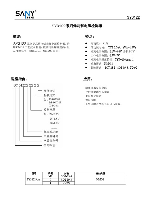
低功耗电压检测器
¾ 在 VIN 脚和输入间接一个电阻,由于 IC 的工作电流流过 VIN 脚,会导致检测和释放电压升高。
¾ 为使用SY3122A系列 IC 稳定工作,应确保 VIN 脚输入频率的上升和下降时间大于几个 u Sec/V。
注意:1、VDF(T) :额定检测电压值 2、释放电压:VDR=VDF+VHYS
VDF*0.99 VDF*0.02
0.7 1.0 3.0 5.0 6.0 7.0
VDF
VDF*0.05 0.7 0.8 0.9 1.0 1.1
2.2 7.7 10.1 11.5 13.0 ±100
VDF*1.01
VDF*0.08
选型指南:
应用:
微处理器复位电路 存贮器电池后备电路 上电复位电路 掉电检测 系统电池寿命和充电电压监视
型号
Hale Waihona Puke 后缀M3SY3122Axx
P
T
封装
SOT-23-3 SOT-89-3
TO-92
输出类型
NMOS
引脚排列图:
SY3122
引脚分配:
SY3122Axx
引脚号
SOT-23 2
SOT-89 TO-92(T)
极限值
8 50 Vss-0.3~Vin+0.3 150 500 300 -40~+85 -40~+125 260℃, 10s
SY3122
单位 V mA V mW mW mW ℃ ℃
主要参数及工作特性: (VDF(T)=2.1V to 3.0V±1% TA=25℃)
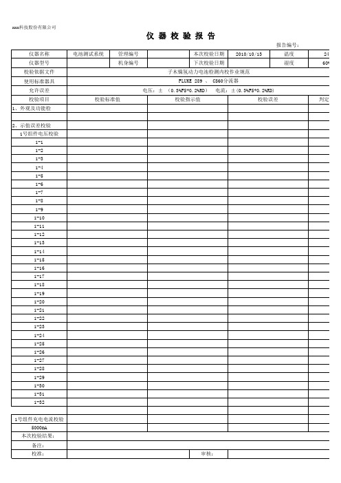
仪器校验报告
本次校验结果: 备注: 校准: 审核:
MF/C 7600 005/ xx科技股份有限公司
仪 器 校 验 报 告
报告编号: 仪器名称 仪器型号 校验依据文件 使用标准器具 允许误差 校验项目 2-29 2-30 2-31 2-32 2号组件充电电流校验 5000mA 10000mA 20000mA 40000mA 2号组件放电电流校验 5000mA 10000mA 20000mA 40000mA 以下空白 校验标准值 电池测试系统 管理编号 机身编号 本次校验日期 下次校验日期 子木镍氢动力电池检测内校作业规范 FLUKE 289 、 CS60分流器 电压:± (0.3%FS+0.2%RD) 校验指示值 电流:±(0.3%FS+0.2%RD) 校验误差 判定结果 2010-10-13 温度 湿度 24℃ 60%RH
子木镍氢动力电池检测内校作业规/C 7600 005/A
xxx科技股份有限公司
仪 器 校 验 报 告
报告编号: 仪器名称 仪器型号 校验依据文件 使用标准器具 允许误差 校验项目 1、外观及功能检 2、示值误差校验 1号组件电压校验 1-1 1-2 1-3 1-4 1-5 1-6 1-7 1-8 1-9 1-10 1-11 1-12 1-13 1-14 1-15 1-16 1-17 1-18 1-19 1-20 1-21 1-22 1-23 1-24 1-25 1-26 1-27 1-28 1-29 1-30 1-31 1-32 1号组件充电电流校验 5000mA 本次校验结果: 备注: 校准: 审核: 校验标准值 电池测试系统 管理编号 机身编号 本次校验日期 下次校验日期 子木镍氢动力电池检测内校作业规范 FLUKE 289 、 CS60分流器 电压:± (0.3%FS+0.2%RD) 校验指示值 电流:±(0.3%FS+0.2%RD) 校验误差 判定结果 2010-10-13 温度 湿度 24℃ 60%RH
MAX811 MAX812 4-Pin μP电压监视器带手动复位输入说明书

MAX811/MAX8124-Pin μP Voltage Monitorswith Manual Reset InputGeneral DescriptionThe MAX811/MAX812 are low-power microprocessor (µP) supervisory circuits used to monitor power sup-plies in µP and digital systems. They provide excellent circuit reliability and low cost by eliminating external components and adjustments when used with 5V-powered or 3V-powered circuits. The MAX811/MAX812 also provide a debounced manual reset input.These devices perform a single function: They assert a reset signal whenever the V CC supply voltage falls below a preset threshold, keeping it asserted for at least 140ms after V CC has risen above the reset thresh-old. The only difference between the two devices is that the MAX811 has an active-low RESET output (which is guaranteed to be in the correct state for V CC down to 1V), while the MAX812 has an active-high RE SE T out-put. The reset comparator is designed to ignore fast transients on V CC. Reset thresholds are available for operation with a variety of supply voltages.Low supply current makes the MAX811/MAX812 ideal for use in portable equipment. The devices come in a 4-pin SOT143package.ApplicationsComputersControllersIntelligent InstrumentsCritical µP and µC Power MonitoringPortable/Battery-Powered Equipment Benefits and Features•Integrated Voltage Monitor Increases System Robustness with Added Manual Reset•Precision Monitoring of 3V, 3.3V, and 5VPower-Supply Voltages•140ms Min Power-On-Reset Pulse Width- RESET Output (MAX811), RESET Output (MAX812)•Guaranteed Over Temperature•Guaranteed RESET Valid to V CC= 1V (MAX811)•Power-Supply Transient Immunity•Saves Board Space•No External Components•4-Pin SOT143 Package•Low Power Consumption Simplifies Power-Supply Requirements•6µA Supply Current1243V CCMR(RESET) RESETGNDMAX811MAX812SOT143TOP VIEW( ) ARE FOR MAX812NOTE: SEE PACKAGE INFORMATION FOR MARKING INFORMATION.Pin ConfigurationTypical Operating CircuitRESET THRESHOLDSUFFIX VOLTAGE (V)L 4.63M 4.38T 3.08S 2.93R 2.63Absolute Maximum RatingsElectrical Characteristics(V CC = 5V for L/M versions, V CC = 3.3V for T/S versions, V CC = 3V for R version, T A = -40°C to +85°C, unless otherwise noted. Typical values are at T= +25°C.) (Note 1)Stresses beyond those listed under “Absolute Maximum Ratings” may cause permanent damage to the device. These are stress ratings only, and functional operation of the device at these or any other conditions beyond those indicated in the operational sections of the specifications is not implied. Exposure to absolute maximum rating conditions for extended periods may affect device reliability.Terminal Voltage (with respect to GND)V CC ......................................................................-0.3V to 6.0V All Other Inputs.......................................-0.3V to (V CC + 0.3V)Input Current, V CC,MR .......................................................20mA Output Current, RESET or RESET .......................................20mAContinuous Power Dissipation (T A = +70°C)SOT143(derate 4mW/°C above +70°C).......................320mW Operating Temperature Range ...........................-40°C to +85°C Storage Temperature Range.............................-65°C to +160°C Lead Temperature (soldering, 10sec).............................+300°CElectrical Characteristics (continued)(V CC= 5V for L/M versions, V CC= 3.3V for T/S versions, V CC= 3V for R version, T A= -40°C to +85°C, unless otherwise noted.Note 1:Production testing done at T A= +25°C, over temperature limits guaranteed by design using six sigma design limits.Note 2:RESET output for MAX811, RESET output for MAX812.Note 3:“Glitches” of 100ns or less typically will not generate a reset pulse.190POWER-UP RESET TIMEOUTvs. TEMPERATURE230TEMPERATURE (°C)P O W E R -U P R E S E T T I M E O U T (m s )210200220-408535-151060RESET THRESHOLD DEVIATIONvs. TEMPERATURE0.99951.00001.0005M A X 811/12-T O C 6TEMPERATURE (°C)N O R M A L I Z E D T H R E S H O L D (V )0.99850.99800.9990-408535-1510600POWER-DOWN RESET DELAY vs. TEMPERATURE(MAX81_L/M)200TEMPERATURE (°C)P O W E R -D O W N R E S E T D E L A Y (μs )10050150-408510-156035Typical Operating Characteristics(T A = +25°C, unless otherwise noted.)0-4085SUPPLY CURRENT vs. TEMPERATURE(MAX81_R/S/T)2.02.53.0TEMPERATURE (°C)S U P P L Y C U R R E N T (μA )101.00.5-15601.535SUPPLY CURRENT vs. TEMPERATURE(MAX81_L/M)8TEMPERATURE (°C)S U P P L Y C U R R E N T (μA )426-408510-1560350POWER-DOWN RESET DELAY vs. TEMPERATURE(MAX81_R/S/T)80100TEMPERATURE (°C)P O W E R -D O W N R E S E T D E L A Y (μs )402060-408510-156035Pin DescriptionDetailed DescriptionReset OutputA microprocessor’s (µP’s) reset input starts the µP in a known state. These µP supervisory circuits assert reset to prevent code execution errors during power-up,power-down, or brownout conditions.RESET is guaranteed to be a logic low for V CC > 1V.Once V CC exceeds the reset threshold, an internal timer keeps RESET low for the reset timeout period;after this interval, RESET goes high.If a brownout condition occurs (V CC dips below the reset threshold), RESET goes low. Any time V CC goes below the reset threshold, the internal timer resets to zero, and RESET goes low. The internal timer starts after V CC returns above the reset threshold, and RESET remains low for the reset timeout period.The manual reset input (MR ) can also initiate a reset.See the Manual Reset Input section.The MAX812 has an active-high RE SE T output that is the inverse of the MAX811’s RESET output.Manual Reset InputMany µP-based products require manual reset capabil-ity, allowing the operator, a test technician, or external logic circuitry to initiate a reset. A logic low on MR asserts reset. Reset remains asserted while MR is low,and for the Reset Active Timeout Period (t RP ) after MR returns high. This input has an internal 20k Ωpull-up resistor, so it can be left open if it is not used. MR can be driven with TTL or CMOS-logic levels, or with open-drain/collector outputs. Connect a normally open momentary switch from MR to GND to create a manual-reset function; external debounce circuitry is not required. If MR is driven from long cables or if the device is used in a noisy environment, connecting a 0.1µF capacitor from MR to ground provides additional noise immunity.Reset Threshold AccuracyThe MAX811/MAX812 are ideal for systems using a 5V ±5% or 3V ±5% power supply with ICs specified for 5V ±10% or 3V ±10%, respectively. They are designed to meet worst-case specifications over temperature. The reset is guaranteed to assert after the power supply falls out of regulation, but before power drops below the minimum specified operating voltage range for the system ICs. The thresholds are pre-trimmed and exhibit tight distribution, reducing the range over which an undesirable reset may occur.Manual Reset Input. A logic low on MR asserts reset. Reset remains asserted as long as MR is low and for 180ms after MR returns high. This active-low input has an internal 20k Ωpull-up resistor. It can be driven from a TTL or CMOS-logic line, or shorted to ground with a switch.Leave open if unused.33+5V, +3.3V, or +3V Supply Voltage44Active-High Reset Output. RESET remains high while V CC is below the reset threshold or while MR is held low. RESET remains high for Reset Active Timeout Period (t RP ) after the reset condi-tions are terminated.2—Active-Low Reset Output. RESET remains low while V CC is below the reset threshold or while MR is held low. RESET remains low for the Reset Active Timeout Period (t RP ) after the reset conditions are terminated.—2Ground11FUNCTIONPINMRV CCRESETRESETGND NAME MAX811MAX812Applications InformationNegative-Going V CC TransientsIn addition to issuing a reset to the µP during power-up, power-down, and brownout conditions, the MAX811/ MAX812 are relatively immune to short duration nega-tive-going V CC transients (glitches).Figure 1 shows typical transient durations vs. reset comparator overdrive, for which the MAX811/MAX812 do not generate a reset pulse. This graph was generat-ed using a negative-going pulse applied to V CC, start-ing above the actual reset threshold and ending below it by the magnitude indicated (reset comparator over-drive). The graph indicates the typical maximum pulse width a negative-going V CC transient may have without causing a reset pulse to be issued. As the magnitude of the transient increases (goes farther below the reset threshold), the maximum allowable pulse width decreases. Typically, a V CC transient that goes 125mV below the reset threshold and lasts 40µs or less (MAX81_L/M) or 20µs or less (MAX81_T/S/R) will not cause a reset pulse to be issued. A 0.1µF capacitor mounted as close as possible to V CC provides addi-tional transient immunity.Ensuring a Valid RESET OutputDown to V CC= 0VWhen V CC falls below 1V, the MAX811 RESET output no longer sinks current—it becomes an open circuit. Therefore, high-impedance CMOS-logic inputs con-nected to the RESET output can drift to undetermined voltages. This presents no problem in most applica-tions, since most µP and other circuitry is inoperative with V CC below 1V. However, in applications where the RESET output must be valid down to 0V, adding a pull-down resistor to the RESET pin will cause any stray leakage currents to flow to ground, holding RESET low (Figure 2). R1’s value is not critical; 100kΩis large enough not to load RESET and small enough to pull RESET to ground.A 100kΩpull-up resistor to V CC is also recommended for the MAX812 if RESET is required to remain valid for V CC< 1V.Interfacing to μPs with Array Bidirectional Reset PinsµPs with bidirectional reset pins (such as the Motorola 68HC11 series) can contend with the MAX811/MAX812 reset outputs. If, for example, the MAX811 RESET out-put is asserted high and the µP wants to pull it low, indeterminate logic levels may result. To correct such cases, connect a 4.7kΩresistor between the MAX811 RESET(or MAX812 RESET) output and the µP reset I/O (Figure 3). Buffer the reset output to other system com-ponents.Chip InformationTRANSISTOR COUNT: 341Package InformationFor the latest package outline information and land patterns (footprints), go to /packages. Note that a “+”, “#”, or “-” in the package code indicates RoHS status only. Package drawings may show a different suffix character, but the drawing pertains to the package regardless of RoHS status.Revision HistoryFor pricing, delivery, and ordering information, please contact Maxim Direct at 1-888-629-4642, or visit Maxim Integrated’s website at . Maxim Integrated cannot assume responsibility for use of any circuitry other than circuitry entirely embodied in a Maxim Integrated product. No circuit patent licenses are implied. Maxim Integrated reserves the right to change the circuitry and specifications without notice at any time. The parametric values (min and max limits) shown in the Electrical Characteristics table are guaranteed. Other parametric values quoted in this data sheet are provided for guidance.。
- 1、下载文档前请自行甄别文档内容的完整性,平台不提供额外的编辑、内容补充、找答案等附加服务。
- 2、"仅部分预览"的文档,不可在线预览部分如存在完整性等问题,可反馈申请退款(可完整预览的文档不适用该条件!)。
- 3、如文档侵犯您的权益,请联系客服反馈,我们会尽快为您处理(人工客服工作时间:9:00-18:30)。
________________________________________________________________ Maxim Integrated Products 1
For free samples & the latest literature: , or phone 1-800-998-8800. For small orders, phone 1-800-835-8769.
o Precision Monitoring of 3V, 3.3V, and 5V Power-Supply Voltages
o 6µA Supply Current o 140ms Min Power-On Reset Pulse Width;
RESET Output (MAX811), RESET Output (MAX812) o Guaranteed Over Temperature o Guaranteed RESET Valid to VCC = 1V (MAX811) o Power-Supply Transient Immunity o No External Components o 4-Pin SOT143 Package
4-Pin µP Voltage Monitors with Manual Reset Input
MAX811/MAX812
ABSOLUTE MAXIMUM RATINGS
Terminal Voltage (with respect to GND) VCC ......................................................................-0.3V to 6.0V All Other Inputs.......................................-0.3V to (VCC + 0.3V)
4.30 4.38 4.46
TA = -40°C to +85°C 4.25
4.50
TA = +25°C
3.03 3.08 3.14 V
TA = -40°C to +85°C 3.00
3.15
TA = +25°C
2.88 2.93 2.98
TA = -40°C to +85°C 2.85
3.00
Reset Threshold Tempco
Continuous Power Dissipation (TA = +70°C) SOT143 (derate 4mW/°C above +70°C) 320mW
Operating Temperature Range ...........................-40°C to +85°C Storage Temperature Range .............................-65°C to +160°C Lead Temperature (soldering, 10sec) .............................+300°C
RESET THRESHOLD
SUFFIX
VOLTAGE (V)
L
4.63
M
4.38
T
3.08
S
2.93
R
2.63
___________________Pin Configuration
VCC
VCC
MAX811 MAX812
RD
PUSHBUTTON SWITCH
VCC
µP
ICC
MAX81_R/S/T, VCC = 3.6V, IOUT = 0
6
15
µA
2.7
10
MAX81_L
TA = +25°C
4.54 4.63 4.72
TA = -40°C to +85°C 4.50
4.75
Reset Threshold
MAX81_M VTH MAX81_T
MAX81_S
TA = +25°C
PARAMETER
SYMBOL
CONDITIONS
MIN TYP MAX UNITS
Operating Voltage Range Supply Current
VCC
TA = 0°C to +70°C TA = -40°C to +85°C
1.0
5.5
V
1.2
MAX81_L/M, VCC = 5.5V, IOUT = 0
VIH
VIL
VCC > VTH(MAX), MAX81_L/M
VIH
VCC > VTH(MAX), MAX81_R/S/T
VIL
VOH VOL
ISOURCE = 150µA, 1.8V < VCC < VTH(MIN)
MAX812R/S/T only, ISINK = 1.2mA, VCC = VTH(MAX)
These devices perform a single function: They assert a reset signal whenever the VCC supply voltage falls below a preset threshold, keeping it asserted for at least 140ms after VCC has risen above the reset threshold. The only difference between the two devices is that the MAX811 has an active-low RESET output (which is guaranteed to be in the correct state for VCC down to 1V), while the MAX812 has an active-high RESET output. The reset comparator is designed to ignore fast transients on VCC. Reset thresholds are available for operation with a variety of supply voltages.
Stresses beyond those listed under “Absolute Maximum Ratings” may cause permanent damage to the device. These are stress ratings only, and functional operation of the device at these or any other conditions beyond those indicated in the operational sections of the specifications is not implied. Exposure to absolute maximum rating conditions for extended periods may affect device reliability.
Low supply current makes the MAX811/MAX812 ideal for use in portable equipment. The devices come in a 4-pin SOT143 package.
________________________Applications
ELECTRICAL CHARACTERISTICS
(VCC = 5V for L/M versions, VCC = 3.3V for T/S versions, VCC = 3V for R version, TA = -40°C to +85°C, unless otherwise noted. Typical values are at TA = +25°C.) (Note 1)
Input Current, VCC, MR .......................................................20mA Output Current, RESET or RESET .......................................20mA
_______________Ordering Information
PART*
TEMP. RANGE PIN-PACKAGE
MAX811_EUS-T -40°C to +85°C 4 SOT143
MAX812_EUS-T -40°C to +85°C 4 SOT143
* This part offers a choice of five different reset threshold voltages. Select the letter corresponding to the desired nominal reset threshold voltage, and insert it into the blank to complete the part number.
MAX812L/M only, ISINK = 3.2mA, VCC = VTH(MAX)
2.3
0.7 x VCC
0.8 V
0.25 x VCC
Computers
Controllers
Intelligent Instruments
Critical µP and µC Power Monitoring