德国西门子D1设备中文WPC4
DVP-04AD
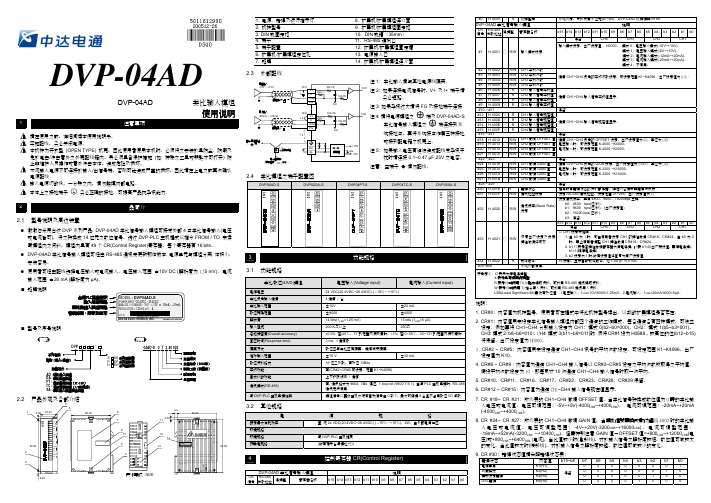
2.2 產品外觀及各部介紹
4
5
1
3.00 25.20
60.00
90.00 2
3
V+
I+
C H
COM 1
FG
V+
I+
C H
COM 2
FG
●
V+
I+
C H
COM 3
FG
V+
I+
C H
COM4
FG
●
序號
S SS 系列主機用 P EP 系列主機用 H EH 系列主機用
04AD-S 0 T 2 40 003
製造序號 生產週次 生產年份(2002年) 製造工廠(桃園廠) 版本序號 生產機種
COM V+ I+ COM
FG
3
3.1 功能規格
類比/數位(4A/D)模組
電源電壓 類比訊號輸入通道 類比輸入範圍 數位轉換範圍 解析度 輸入阻抗 總和精密度(Overall accuracy) 回應時間(Response time) 隔離方式 絕對輸入範圍 數位資料格式 平均功能 自我診斷功能
通訊模式(RS-485)
CH2 平均次數 CH3 平均次數 CH4 平均次數
通道 CH1~CH4 訊號的平均次數設定,可設定範圍 K1~K4096。出廠設定值為 K10。
CH1 輸入信號平均值
CH2 輸入信號平均值 CH3 輸入信號平均值
通道 CH1~CH4 輸入信號平均值顯示。
CH4 輸入信號平均值
保留。
CH1 輸入信號現在值
DVP-04AD
DVP-04AD
類比輸入模組
使用說明
西门子电力保护设备:高压冲击抵挡器产品指南说明书
/arrestersHP-AR 41 2017Siemens medium- and high-voltage surge arresters ensure optimal protection against lightning and switching overvol-tages in electrical power supply applications. Every single arrester incorporates the results of continuous research and development based on extensive know-how and worldwide experience since 1925. That’s why Siemens surge arresters are renowned for uncompromising quality and a long service life.Optimal solutions for rail systemsIn railway systems Siemens surge arresters help make sure that lightning overvoltages do not result in damage to the insulation in system components and the traction vehicles themselves. They protect traction substations, transmission lines, cables, and catenary systems as well as rail vehicles for local, long distance, and high speed services.Siemens surge arresters meet all worldwide requirements for the overvoltage protection of rail vehicles and railSiemens surge arresters for railway applications – reliable, stable and safe overvoltage protectionSiemens surge arresters for rail applications are per f ectly suited for every rail system, e.g.:• High-speed and intercity trains • Commuter and regional trains • Urban transport: Light rail, metros, streetcars, eBus • Locomotives • Propulsion systems • Rail electrification• Power supply for catenary systems • Substations• Surge arresters for A1 and A2 applicationsAnd for every rail power system, e.g.:• 12.5 kV, 25 Hz / 60 Hz • 15 kV, 16 2/3 Hz • 25 kV, 50 Hz / 60 Hz • 750 V DC • 1500 V DC • 3000 V DCelectrification. The comprehensive portfolio makes it pos-sible to find the ideal surge arrester for any conceivable application and meet even specific demands, such as:• high mechanical stability to withstand vibrations and high wind speeds• extremely reliable pressure relief behavior when special protection is required• excellent pollution layer characteristics for coastal and desert regions and areas with extreme air pollution Standards and testing – reliability you can count on Siemens surge arresters for rail applications comply with the latest versions of• IEC 60099-4, Metal-oxide surge arresters without gaps for AC systems• DIN EN 50526-1, Railway applications – DC surge arrest-ers and voltage limiting devices• DIN EN 45545-2, Railway applications – Fire protection on railway vehicles• IEC 61373, Railway applications – Rolling stock equip-ment – Shock and vibration tests(tests performed by independent laboratories, reports available on request)Every Siemens surge arrester for rail applications undergoes a routine test and comes with a routine test certificate.Siemens meets all requirements of ISO 9001:2008, ISO 14002:2004, and BS OHSAS 18001:2007. AllSiemens suppliers are certified according to ISO standards or audited by Siemens. Siemens’ corporate quality guide-lines ensure sustainable quality improvement.2Product rangeSiemens offers different surge arrester types for AC and DC applications.33EB4 Silicone rubber surge arrester with composite hollow core design6123451Silicone rubber sheds directly molded on FRP tube 2FRP tube3End fitting with directional pressure relief device and sealing system 4Directional pressure relief device 5Metal oxide resistors 6Arcing hornReliable and safe: 3EB4 railway surge arresters3EB4 railway surge arresters were designed to ensure outstanding safety and durability. They are hydrophobic and also withstand exposure to weather extremes, tem-peratures from –40 °C to +70 °C, and the effects of UV radiation. Resilient technology and durable materials ensure smooth operation under all conditions.Siemens’ reliable and innovative composite hollow core design uses silicone which is directly molded onto a fiber-glass reinforced plastic (FRP) tube. This ensures an enor-mous withstand capability against mechanical forces. An excellent special sealing of the flanges at both ends of the surge arrester prevents partial discharges and moisture ingress and ensures decades of trouble-free service.In the case of an overload or the extremely rare case of an arrester short circuit, the arc escapes directly through adirectional pressure relief device. This makes it possible to point the surge arrester in a direction that will minimize the risk of any damage to the equipment and passengersnearby. Internal parts are not ejected and the shatterproof housing does not break.3EB4 railway surge arresters are suitable for rail vehicles with speeds of up to 420 km/h (260 mph) and for station-ary applications in areas accessible to the public.45Surge arrester 3EB4 – characteristics673EB5 Surge arresters with silicone rubber housing and Cage Design™123 441Cage of FRP rods2Metal oxide resistors3Silicone rubber sheds directly molded on metal oxide resistors and on end-fittings4End-fittingsThe innovative Cage Design™ of Siemens 3EB5 rail surge arresters ensures high mechanical strength, safe overload performance, and maintenance-free, reliable service: The metal oxide resistors (MOVs) are enclosed by a cage made of fiber-glass reinforced plastic (FRP) rods. This rigid, rein-forced structure ensures high mechanical strength. The self-extinguishing and flame retardant silicone rubber housing is directly molded onto the MOVs and the FRP rods for excellent sealing. All components are completely em-bedded, inclusions and gaps are avoided, partial discharges and moisture are prevented. The hydrophobic silicone rubber is permanently water-repellent and stain-resistant, which results in high tracking and erosion resistance. Since the MOVs are not enclosed in a sealed mechanical shell, the arc can escape directly through the soft silicone housing in the extremely rare event of the MOVs being overloaded. Arcing cannot lead to critical internal pressure, the mechanical support structure of the enclosure remains unharmed, the ejection of internal parts that could damage other equipment nearby is prevented almost completely. 3EB5 railway surge arresters are suitable for rail vehicles with speeds of up to 320 km/h (200 mph) and for station-ary application in areas accessible to the public.89Surge arrester 3EB5 – characteristics10113EB2 and 3EB3 surge arresters for A1and A2 applicationsRecommendation for applications in DC systems according to VDV 525*• Rails of DC railway systems that are isolated from earth require low-resistance tower footings, driven piles, the reinforcements of concrete tracks, or separate earth rods for earth termination.• Rails without any additional isolation generally have a low leakage resistance and can be used as earth termina-tions. Surge currents will simply be discharged through the rails. However, this endangers electrical and elec-tronic equipment near or on the tracks. Additional surge arresters within such equipment provide an effective remedy in this case. Full protection for the catenary is provided by installing outdoor surge arresters with VDV 525 “A1” designation at:• every power feeding point• the ends of feeding sections and dead-end feeders • coupling points• current tapsAdditional “A1” surge arresters are recommended if sec-tions are often hit by lightning strikes, e.g. on bridges or on open stretches.12Lightning protection of supply and return lines at substa-tions requires:• “A1” type surge arresters connected between section circuit breakers/cable terminals and the return line.• “A2” type surge arresters between return line and struc-ture earth to limit the unavoidable potential rise in a return line caused by a lightning surge current.Even though MOV surge arresters have failure rates well below 0.1 percent per year, a failure may occur and lead to permanent conductivity of the “A1” type surge arresters, resulting in inadmissibly high fault voltage on the ground electrode for a long time. An additional “A2” type surge arrester with a low continuous operating voltage (120 V ≤ U c ≤ 300 V) connected between the ground electrode andthe return line is intentionally overloaded in this case to limit the fault voltage and trip the section circuit breaker due to feeding from the catenary system.* Publication No. 525 of the “Verband deutscher Verkehrsunterneh-men (VDV)” (Association of German Transportation Companies), which provides operators of DC railways with recommendations for effective overvoltage protection in case of lightning strikes.13Packing dimensionsAn overview of replacement types of phased-out surge arresters for rail systems is shown in the table below.Replacement ofphased-out surge arresters14Related catalogues and brochures15Published by and copyright © 2017: Siemens AGEnergy ManagementHigh Voltage Products Freyeslebenstrasse 191058 Erlangen, GermanySiemens AGEnergy ManagementHigh Voltage Products Nonnendammallee 10413629 Berlin, GermanyFor more information,please contact us atPhone: +49 30 386 33 222Fax: +49 30 386 26 721E-mail:*************************** /arrestersArticle No. EMHP-B10024-00-7600 Dispo 30002fb 7737 WS 08171.0Printed in GermanyAll rights reserved.Trademarks mentioned in this documentare the property of Siemens AG, its affiliates, or their respective owners.Subject to changes and errors. The information given in this document only contains general descriptions and/or performance features which may not always specifically reflect those descri-bed, or which may undergo modification in the course of further development of the products. The requested performance features are binding only when they are expressly agreed upon in theconcluded contract.。
西门子贴片机技术规范
5,GF的维护 1)SMT编程员在编制首次生产程序时,如发现有新器件则必须在标准GF库中给该器件选用一合适的 GF,如库中没有,则需新建。 2)工程师/技术员在首次试产调试中发现GF有问题,需确认是否是选错GF,如需要新建的GF,则按要 求命名,成熟后须纳入标准GF库中。 3)生产中为解决打翻、漏贴、侧立等问题及解决一些特殊器件的识别问题而建立的GF;需新命名且须 跟踪该GF的使用情况。,如应用成熟后须纳入标准GF库中覆盖原GF,然后删除临时建立的GF, 否则予以删除。并周知其他工程师/技术员 SMT编程员。 4)SMT编程员根据工程师/技术员的反馈情况对线控机GF 、BE、文件 检查确认并维护。
二、定义
• • • 1,元件方向的定义: 规则 1:元件定义时应俯视。 规则 2:长轴为X轴,短轴为Y轴。例外:图④元件顶面有一凹槽时,吸嘴无法放入,应旋转90度。
规则 2: 1号引脚应位于元件的左下角,如果是二极管,元件的正极必须指向X方向。
规则 3: 在宽度方向,引脚多的一边应指向底部。
规则 4: 当元件有特殊引脚时,比如有一个较宽的引脚,这个特殊引脚应位于元件底部。
检查真空值是否符合要求,检查真空发生器工作是否正常。 修改元件参数,亮度的调整以突出引脚的对比度为宜,以 使机器能较好的识别引脚。 IQC做好来料检测,跟元件供应商联系; 供料器调整,清扫供料器平台,更换已坏部件或供料器;
经验小结: 抛料原因从过程中分析可分为两大类,一为吸嘴可良好的吸取元件,二为吸嘴不能吸取元件。前者是参数等 设置不当,导致机器不能正确识别而抛料。 后者原因较多,可能为为架不良,参数设置不当,吸嘴不当等原因。 总之, 抛料的原因需要仔细的观察,通过现象寻找到真正的原因,同时在分析的过程中需要对整个机器原理及PRO里的参数有 较学的认识才能较好、快速的解决问题。
SMT贴片机基础培训
西门子贴片机简述(七)
SIEMENS貼片机的型号及含义﹕
2. HSxx
如﹕HS50 其中HS代表HIGH SPEED 超高速機 50代表理想狀態的关键技术——各种SMD的开发与制造技术 片时元器件
产品设计——结构设计,端子形状,尺寸精度,可焊型
包装——盘带式,棒式,华夫盘,散装式 焊锡膏与无铅焊料 黏接剂/贴片胶 助焊剂 导电胶
贴装材料
表 面 组 装 技 术
基板材料:有机玻璃纤维,陶瓷板,合金板 贴装印制板 电路图形设计:图形尺寸设计,工艺型设计 锡膏精密印刷工艺 涂布工艺 装联工艺 贴装方式 贴片胶精密点涂工艺及固化工艺 纯片式元件贴装,单面或双面 SMD与通孔元件混装,单面或双面
1)、机械对中调整位臵、吸嘴旋转调整方向,这种方法能达到的精度 有限,较晚的机型已再不采用。 2)、相机识别、X/Y坐标系统调整位臵、吸嘴自旋转调整方向,相机固 定,贴片头飞行划过相机上空,进行成像识别。
SMT 贴片机简述(三)
转塔型(Turret)
一般,转塔上安装有十几到二十几个贴片头,每个贴片头上安装2~4 个真空吸嘴(较早机型)至5~6个真空吸嘴(现在机型)。由于转塔的特 点,将动作细微化,选换吸嘴、送料器移动到位、取元件、元件识 别、角度调整、工作台移动(包含位臵调整)、贴放元件等动作都可 以在同一时间周期内完成,所以实现真正意义上的高速度。目前最 快的时间周期达到0.08~0.10秒钟一片元件 此机型在速度上是优越的,适于大批量生产,但其只能用带状包装 的元件,如果是密脚、大型的集成电路(IC),只有托盘包装,则无 法完成,因此还有赖于其它机型来共同合作。这种设备结构复杂, 造价昂贵,最新机型约在US$50万,是拱架型的三倍以上。
电路基板-----但(多)层PCB, 陶瓷,瓷釉金属板等
西门子股份公司 DIGSI CFC 说明书
CFC 使用手册 E50417-H115D-C098-A1
iii
目录
2.7 2.7.1 2.7.2 2.7.3 2.8 2.8.1 2.8.2 2.8.3 2.8.4 测量值处理实例..................................................................................................................35 连接输入信号 .....................................................................................................................36 连接功能块 .........................................................................................................................37 连接输出信号 .....................................................................................................................38 联锁实例 ............................................................................................................................39 连接输入信号 .....................................................................................................................40 增加输入信号的数目...........................................................................................................41 连接功能块 .........................................................................................................................42 连接输出信号 .....................................................................................................................43
西门子工控机
© Siemens AG 2013Answers for industry.SIMATIC IPC更强大的工业PC新品惠选,同赢之道SIMATIC IPC —更强大的工业PC 更加坚固耐用及长期可用性更加坚固耐用及长期可用性SIMATIC IPC是为了满足恶劣工业环境对工业PC产品可靠性的高要求而设计研发的。
其卓越的产品特性体现在如下方面:• 主板由西门子自主研发设计• 坚固的外壳设计,具有较高电磁兼容性,且防护等级可达IP65/NEMA4• 采用工业电源(基于NAMUR标准),冗余电源可在正常运行期间进行切换• 即使工作在有较大温差的环境下,也可确保很长的平均无故障时间• 特殊的硬盘安装方式保证了高抗震防冲击能力• 线缆连接头的卡扣设计和板卡固定架设计确保插接可靠性• 内置USB接口,可用于保护软件狗不被误拔• 已安装并激活的微软操作系统节省客户安装时间• 方便维护的模块化设计• 可使用恢复光盘将机器恢复至出厂状态更多系统可用性在评估一个自动化解决方案总体拥有成本 (TCO) 时,系统故障和停产造成的费用是最主要的部分。
SIMATIC IPC产品的高性能和大量可选附件可持续保证系统的长期可用性,从而在确保最大生产率的同时,减少因故障造成的费用。
通过SIMATIC IPC和系统可用组件降低总体拥有成本相对较低的费用实现最大系统可用性由于系统故障造成的停机费用用于以下各项的费用• 维护/支持• 更新/修改• 调试• 执行• 采购• 规划系统总拥有成本分析(TCO)SIMATIC IPC —更强大的工业PC/the-more-industrial-pcSIMATIC 机架式PC实例坚固的外壳设计,具有很高的电磁兼容性(EMC)板卡固定架设计,增强扩展卡在振动冲击情况下的连接可靠性带转速监控的系统风扇,实现机箱内部正向负压,有效防尘免工具更换过滤网采用工业电源(符合NAMUR标准),瞬时压降可达20毫秒,冗余电源可在机器正常运行期间进行切换特殊的硬盘托架设计增强硬盘抗震防冲击能力线缆卡扣设计确保线缆插接可靠性内置USB接口,可防止未经授权地拔出软件加密狗2更多产品型号与选择方案SIMATIC IPC产品类型丰富,提供多种设计和功能。
PSS-WD001A-EN-P-2004 电子输入输出引脚图说明书

PublicationPSS-WD001A-EN-P - September 2004Wiring DiagramsPinout Guide for Digital I/OPackage ContentsYour package contains:•one module•these pinout guide wiring instructionsInstallation instructions for the following modules are found in the publications listed below .Module Catalog Number PublicationNumber24V dc Output PSST8M8APSST8M12APSST8M23AE107P 24V dc Input PSSN8M12APSSN8M8APSSP8M12APSSP8M8AE106P 24V dc Input PSSN8M23APSSP8M23A E108P2 Pinout Guide for Digital I/OPublication PSS-WD001A-EN-P - September2004 PSST8M8A(view into connector)Pin 1 - 24V dcPin 3 - CommonPin 4 - Output 0 (M8-A)Output 1 (M8-B)Output 2 (M8-C)Output 3 (M8-D)Output 4 (M8-E)Output 5 (M8-F)Output 6 (M8-G)Output 7 (M8-H)24V dcOutput 1 (M12-A)Pin 4 -Output 0 (M12-A)Output 3 (M12-B)Output 2 (M12-B)Output 5 (M12-C)Output 4 (M12-C)Output 7 (M12-D)Output 6 (M12-D)CommonPin 5 -No Connect (view into connector)Pin 1 -Output 0Pin 7 -Output 6Pin 2 -Output 1Pin 8 -Output 7Pin 3 -Output 2Pin 9 -Return (Com)Pin 4 -Output 3Pin 10 - Return (Com)Pin 5 -Output 4Pin 11 - 24V dc Pin 6 -Output 5Pin 12 - ChassisPinout Guide for Digital I/O 3Publication PSS-WD001A-EN-P - September 2004PSSN8M8A and PSSP8M8A(view into connector)Pin 1 - 24V dcPin 4 - Input 0 (M8-A)Pin 3 - Common Input 1 (M8-B)Input 2 (M8-C)Input 3 (M8-D)Input 4 (M8-E)Input 5 (M8-F)Input 6 (M8-G)Input 7 (M8-H) 24V dcInput 1 (M12-A)Pin 4 -Input 0 (M12-A)Input 3 (M12-B)Input 2 (M12-B)Input 5 (M12-C)Input 4 (M12-C)Input 7 (M12-D)Input 6 (M12-D)CommonPin 5 -No Connect (view into connector)Pin 1 -Input 0Pin 7 - Input 6Pin 2 -Input 1Pin 8 - Input 7Pin 3 -Input 2Pin 9 - Return (Com)Pin 4 -Input 3Pin 10 - Return (Com)Pin 5 -Input 4Pin 11 - 24V dc Pin 6 -Input 5Pin 12 - Chassis4 Pinout Guide for Digital I/OPublication PSS-WD001A-EN-P - September2004Specifications Operating Temperature -20 to 60°C (-4 to 140°F)Operating Voltage 10-28.8V dc Output Current 1.0 A per output (not to exceed 3 A)Certifications:(when product is marked)CE European Union 89/336/EEC EMC Directive,compliant with:EN 61000-6-4; Industrial EmissionsEN 50082-2; Industrial ImmunityEN 61326; Meas./Control/Lab., Industrial RequirementsEN 61000-6-2; Industrial ImmunityC-TickAustralian Radiocommunications Act,compliant with: AS/NZS CISPR 11; Industrial Emissions This equipment is considered Group 1, Class A industrial equipment according to IEC/CISPR Publication 11.Without appropriate precautions, there may be potential difficulties ensuring electromagnetic compatibility in other environments due to conducted as well as radiated disturbance.Pinout Guide for Digital I/O 5 To avoid unpredictable system behavior that can causepersonal injury and property damage: •Disconnect electrical supply (when necessary) before installation, servicing, or conversion. •Disconnect air supply and depressurize all air linesconnected to this product before installation,servicing, or conversion.•Operate within the manufacturer's specified pressure, temperature, and other conditions listed in theseinstructions.•Medium must be moisture-free if ambienttemperature is below freezing.•Service according to procedures listed in theseinstructions.•Installation, service, and conversion of these products must be performed by knowledgeable personnelwho understand how pneumatic products are to be applied.•After installation, servicing, or conversion, air andelectrical supplies (when necessary) should beconnected and the product tested for proper function and leakage. If audible leakage is present, or theproduct does not operate properly, do not put into use.•Warnings and specifications on the product shouldnot be covered by paint, etc. If masking is notpossible, contact your local representative forreplacement labels.Publication PSS-WD001A-EN-P - September 20046 Pinout Guide for Digital I/OFAILURE OR IMPROPER SELECTION OR IMPROPER USEOF THE PRODUCTS AND/OR SYSTEMS DESCRIBEDHEREIN OR RELATED ITEMS CAN CAUSE DEATH,PERSONAL INJURY AND PROPERTY DAMAGE.This document and other information from Parker-Hannifin Corporation, its subsidiaries and authorizeddistributors provide product and/or system options forfurther investigation by users having technical expertise.It is important that you analyze all aspects of yourapplication, including consequences of any failure andreview the information concerning the product orsystems in the current product catalog. Due to the varietyof operating conditions and applications for theseproducts or systems, the user, through its own analysisand testing, is solely responsible for making the finalselection of the products and systems and assuring thatall performance, safety and warning requirements of theapplication are met.The products described herein, including withoutlimitation, product features, specifications, designs,availability and pricing, are subject to change by Parker-Hannifin Corporation and its subsidiaries at any timewithout notice.Publication PSS-WD001A-EN-P - September2004Pinout Guide for Digital I/O 7 Notes:Publication PSS-WD001A-EN-P - September 2004Parker and Parker-Hannifin are trademarks of Parker-Hannifin Corporation.Publication PSS-WD001A-EN-P - September 2004 PN 957928-42Printed in the U.S.A.。
Siemens DP880-1C1-2AB电动器产品说明书
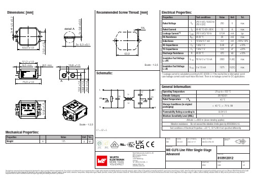
Dimensions: [mm]Scale - 1:2,5Würth Elektronik eiSos GmbH & Co. KGEMC & Inductive SolutionsMax-Eyth-Str. 174638 WaldenburgGermany810912012Würth Elektronik eiSos GmbH & Co. KGEMC & Inductive Solutions810912012 Max-Eyth-Str. 174638 WaldenburgGermanyTest Setup:1Port 11´ (GND)Port 33´ (GND)Würth Elektronik eiSos GmbH & Co. KG EMC & Inductive Solutions Max-Eyth-Str. 174638 Waldenburg Germany810912012Würth Elektronik eiSos GmbH & Co. KGEMC & Inductive Solutions810912012 Max-Eyth-Str. 174638 WaldenburgGermanyCautions and Warnings:The following conditions apply to all goods within the product series of WE-CLFS of Würth Elektronik eiSos GmbH & Co. KG:General:•This electronic component was designed and manufactured for use in general electronic equipment.•Würth Elektronik must be asked for written approval (following the PPAP procedure) before incorporating the components into any equipment in fields such as military, aerospace, aviation, nuclear control, submarine, transportation (automotive control, train control,ship control), transportation signal, disaster prevention, medical, public information network, etc. where higher safety and reliability are especially required and/or if there is the possibility of direct damage or human injury.•Electronic components that will be used in safety-critical or high-reliability applications, should be pre-evaluated by the customer. •The component is designed and manufactured to be used within the datasheet specified values. If the usage and operation conditions specified in the datasheet are not met, the wire insulation may be damaged or dissolved. •Do not drop or impact the components, the component may be damaged.•Würth Elektronik products are qualified according to international standards, which are listed in each product reliability report. Würth Elektronik does not guarantee any customer qualified product characteristics beyond Würth Elektroniks’ specifications, for its validity and sustainability over time.•The customer is responsible for the functionality of their own products. All technical specifications for standard products also apply to customer specific products.Product specific:Cleaning and Washing:•Washing agents used during the production to clean the customer application might damage or change the characteristics of the component. Washing agent may have a negative effect on the long-term functionality of the product.Storage Conditions:• A storage of Würth Electronik products for longer than 12 months is not recommended. Within other effects, the terminals may suffer degradation, resulting in bad solderability. Therefore, all products shall be used within the period of 12 months based on the day of shipment.•Do not expose the components to direct sunlight.•The storage conditions in the original packaging are defined according to DIN EN 61760-2.•The storage conditions stated in the original packaging apply to the storage time and not to the transportation time of the components.Packaging:•The packaging specifications apply only to purchase orders comprising whole packaging units. If the ordered quantity exceeds or is lower than the specified packaging unit, packaging in accordance with the packaging specifications cannot be ensured.Handling:•Violation of the technical product specifications such as exceeding the nominal rated current will void the warranty.•Only qualified personnel should work with the electronic component including, but not limited to, work such as planning, assembly,installation, operation, repair and maintenance considering the corresponding documentation.•The filter includes components storing an electric charge and dangerous voltage may remain at the filter terminals even after the power source has been disconnected even after five minutes.•In case temporary voltage is applied to the unassembled filter, the filter shall be discharged after the power source has been disconnected.•Avoid any overload or conditions that are not specified in the datasheet. •Do not exceed the specified temperature limits.•To maintain regular operation, the filters shall be protected within the application against inadmissible exceedance of the rated current. •The filter leakage current specified in the data sheet merely serves as a user information. For security reasons, the maximum leakage current of the entire electrical application has to be limited. The permissible limits for your application must be acquired from the relative and applicable regulations, provisions and standards.•The current derating must be observed. Disregarding the current derating might result in overheating and in a fire hazard as a consequence thereof.•Due to the heavy weight of the electronic component, strong forces and high accelerations might have the effect to damage the electrical connection and will void the warranty.•The temperature rise of the component must be taken into consideration. The operating temperature is comprised of ambient temperature and temperature rise of the component.The operating temperature of the component shall not exceed the maximum temperature specified.These cautions and warnings comply with the state of the scientific and technical knowledge and are believed to be accurate and reliable.However, no responsibility is assumed for inaccuracies or incompleteness.Würth Elektronik eiSos GmbH & Co. KG EMC & Inductive Solutions Max-Eyth-Str. 174638 Waldenburg GermanyCHECKED REVISION DATE (YYYY-MM-DD)GENERAL TOLERANCEPROJECTION METHODSBir001.0012023-07-17DIN ISO 2768-1mDESCRIPTIONWE-CLFS Line Filter Single-Stage AdvancedORDER CODE810912012BUSINESS UNITSTATUSPAGEImportant NotesThe following conditions apply to all goods within the product range of Würth Elektronik eiSos GmbH & Co. KG:1. General Customer ResponsibilitySome goods within the product range of Würth Elektronik eiSos GmbH & Co. KG contain statements regarding general suitability for certain application areas. These statements about suitability are based on our knowledge and experience of typical requirements concerning the areas, serve as general guidance and cannot be estimated as binding statements about the suitability for a customer application. The responsibility for the applicability and use in a particular customer design is always solely within the authority of the customer. Due to this fact it is up to the customer to evaluate, where appropriate to investigate and decide whether the device with the specific product characteristics described in the product specification is valid and suitable for the respective customer application or not.2. Customer Responsibility related to Specific, in particular Safety-Relevant ApplicationsIt has to be clearly pointed out that the possibility of a malfunction of electronic components or failure before the end of the usual lifetime cannot be completely eliminated in the current state of the art, even if the products are operated within the range of the specifications.In certain customer applications requiring a very high level of safety and especially in customer applications in which the malfunction or failure of an electronic component could endanger human life or health it must be ensured by most advanced technological aid of suitable design of the customer application that no injury or damage is caused to third parties in the event of malfunction or failure of an electronic component. Therefore, customer is cautioned to verify that data sheets are current before placing orders. The current data sheets can be downloaded at .3. Best Care and AttentionAny product-specific notes, cautions and warnings must be strictly observed. Any disregard will result in the loss of warranty.4. Customer Support for Product SpecificationsSome products within the product range may contain substances which are subject to restrictions in certain jurisdictions in order to serve specific technical requirements. Necessary information is available on request. In this case the field sales engineer or the internal sales person in charge should be contacted who will be happy to support in this matter.5. Product R&DDue to constant product improvement product specifications may change from time to time. As a standard reporting procedure of the Product Change Notification (PCN) according to the JEDEC-Standard inform about minor and major changes. In case of further queries regarding the PCN, the field sales engineer or the internal sales person in charge should be contacted. The basic responsibility of the customer as per Section 1 and 2 remains unaffected.6. Product Life CycleDue to technical progress and economical evaluation we also reserve the right to discontinue production and delivery of products. As a standard reporting procedure of the Product Termination Notification (PTN) according to the JEDEC-Standard we will inform at an early stage about inevitable product discontinuance. According to this we cannot guarantee that all products within our product range will always be available. Therefore it needs to be verified with the field sales engineer or the internal sales person in charge about the current product availability expectancy before or when the product for application design-in disposal is considered. The approach named above does not apply in the case of individual agreements deviating from the foregoing for customer-specific products.7. Property RightsAll the rights for contractual products produced by Würth Elektronik eiSos GmbH & Co. KG on the basis of ideas, development contracts as well as models or templates that are subject to copyright, patent or commercial protection supplied to the customer will remain with Würth Elektronik eiSos GmbH & Co. KG. Würth Elektronik eiSos GmbH & Co. KG does not warrant or represent that any license, either expressed or implied, is granted under any patent right, copyright, mask work right, or other intellectual property right relating to any combination,application, or process in which Würth Elektronik eiSos GmbH & Co. KG components or services are used.8. General Terms and ConditionsUnless otherwise agreed in individual contracts, all orders are subject to the current version of the “General Terms and Conditions of Würth Elektronik eiSos Group”, last version available at .Würth Elektronik eiSos GmbH & Co. KG EMC & Inductive Solutions Max-Eyth-Str. 174638 Waldenburg GermanyCHECKED REVISION DATE (YYYY-MM-DD)GENERAL TOLERANCEPROJECTION METHODSBir001.0012023-07-17DIN ISO 2768-1mDESCRIPTIONWE-CLFS Line Filter Single-Stage AdvancedORDER CODE810912012BUSINESS UNITSTATUSPAGE。
- 1、下载文档前请自行甄别文档内容的完整性,平台不提供额外的编辑、内容补充、找答案等附加服务。
- 2、"仅部分预览"的文档,不可在线预览部分如存在完整性等问题,可反馈申请退款(可完整预览的文档不适用该条件!)。
- 3、如文档侵犯您的权益,请联系客服反馈,我们会尽快为您处理(人工客服工作时间:9:00-18:30)。
WPC4
1,皮带张力
(1)L ift axis马达传送皮带:235+-10Hz
(2)F eed axis 马达传送皮带:265+-5Hz
(3)F eed axis 传送盘皮带:105+-5Hz.制具及方法如下图。
2,Feeder axis 钩子(catch unit)与皮带之间的间隙:0.5mm,如下图3的位置.并保证钩子与其他部位没有摩擦。
3,盘传送皮带的要求:
长度:2120mm.
齿数:424
安装如下图
4标准ma
如果上述参数均确定无误,WPC4仍然无法校正。
尝试将其MA修改为标准数据,数据如下:
修改须在操作系统中用notepad打开ma修改。
Sitest 中无法修改。
修改步骤:
(1),进入操作系统界面,找到已经存在的wpc.ma.
(2),用notepad打开文件,并找到相应的参数进行修改。
只需要修改不能校正的轴的参数,不需要全部修改。
(3),进入sitest将修改后的ma存入系统中。
Start SITEST.
Open the menu: SITEST Machine data.
Click on the selection button: Restore WPC machine data … .
Select the data folder.
Click on OK.
具体的标准ma参见附录。