Low-power DA-converters for display applications using stepwise charging and charge recovery
honeywelldc1020说明书
honeywelldc1020说明书Honeywell DC1020 Digital Controller User ManualTable of Contents1Introduction ................................................... ................................................................ . (1)2 ProductOverview ....................................................... (3)2.1 Product Features........................................................ (3)2.2 ProductSpecifications ................................................. . (4)3.1 Wiring andConnections .................................................... (7)DC1020 ......................................................... .. (10)4 Configuring theDC1020 ......................................................... (15)4.1 Setting the InputType ........................................................... (15)4.2 Setting the OutputType ........................................................... (17)4.3 Setting theFunction ....................................................... . (19)5 Operating theDC1020 ......................................................... .. (23)5.1 DisplaySetup .......................................................... .. (23)DC1020 ......................................................... (25)6 Troubleshooting andMaintenance .................................................... (30)6.1Troubleshooting ................................................ .. (30)6.2Maintenance .................................................... (3)27Glossary ....................................................... ................................................................ .. (34)1 IntroductionThe Honeywell DC1020 is a digital controller designed to provide precise control of a process variable such as temperature, pressure, flow, or level. It can be used in a wide range of applications such as HVAC, industrial process control, and chemical process control.The DC1020 features an easy-to-use interface, which allows you to quickly and accurately set up and adjust the controller. The controller features a large backlit LCD display, which makes the information easier to read in all lighting conditions.The DC1020 can be configured for a variety of input, output, and control functions. It can be used in single-loop (with one control output) or dual-loop (with two control outputs) applications. It also supports various control strategies including ON-OFF, PID, On-Shift, Pump Control, and Bang-Bang.The DC1020 has been designed to provide reliable performance, consistent measurements, and long-term stability. The controller features advanced self-diagnostics that helps you quicklypinpoint system problems.The Honeywell DC1020 is designed for use in hazardous areas and is approved for UL, CSA, and ATEX hazardous locations (Class I, Div 1, Group A).2 Product Overview2.1 Product Features• Intuitive user interface with menu-driven programming• 4-digit backlit LCD display for clear readability• Supports a variety of input, output, and control functions • Single-loop or dual-loop control• Advanced self-diagnostics for quick system problem pinpointing• Approved for hazardous areas (UL, CSA, ATEX, Class I, Div 1, Group A)• Includes self-diagnostics, limit alarms, and control output delay2.2 Product SpecificationsInputs• Thermocouple: Types J, K, L, N, S, R, B, T, E•RTD:Pt100,Pt100E,Pt100S,Pt1000• Voltage Input: 0-10V, 0-5V, 0-1V• Current Input: 4-20mA, 0-20mA• Differential Input: 0-20mA• Frequency Input: 0-5KHz• 2-Wire TransmitterOutputs• Relay: 240V AC, 5A•SSR:24VDC,100mA• Voltage: 0-10V, 0-5V, 0-1V• Current: 4-20mA, 0-20mA• Frequency: 0-5KHz• 2-Wire TransmitterControl• ON-OFF, PID, On-Shift, Pump Control, Bang-Bang Accuracy• ±0.1% of Full ScaleAmbient Temperature• 0 to 50°C (32 to 122°F)Power Supply• 100 to 240V AC, 50/60HzDisplay• 4-digit backlit LCDDimensions• W x H x D: 110 x 110 x 54mm (4.3" x 4.3" x 2.1")。
腾讯NDA限制-腾讯NDA限制-Jacinto6Eco SoC电源解决方案-DRA72 TDA2

TPS22965 + TPS51200
8
New PDN Concept
0.40 = $3.25
(3 AVS @ 1‐2.5A, Dual 1.8/3.3V IO, DDR3L)
18 + 4 + 4.6 + 4.6 + 4 + 9 = 44
$4.42 128 $2.53 74
$7.32 190 $4.64 119
5. “PDN’s AVS Capability” is the achievable power if all AVS power rails are increased to 90% of capacity while other power rails remain at typical Use Case modelled values.
(3 AVS @ 1‐3.5A, Dual 1.8/3.3V IO, DDR3L) (similar to EVM PDN #0)
49 + 9 + 4 = 62
#8.2 – LP87524 + LP5912 + TLV713 + LP5907 +
9.92
1.26 + 0.19 + 0.07 + 0.10 + 0.10 +
2. PDN Support component (Rs, Cs & Ls) pricing from Mouser Distribution website using single 4k – 10k/reel qty costs as of May 2016. Both PDN Support & PDN Total Costs have been provided for relative comparison only, individual customer volume pricing may vary.
AURATUS 数字混音台说明书
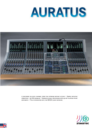
12 encoders on each channel strip for optimum instant access • Simple intuitive operation • 96-KHz enabled • Superior signal processing with 40-bit fl oating-point arithmetic • Fully integrated into the NEXUS audio networkAURATUSThe basic idea behind the AURATUS was to develop a compact digital con-sole suitable for predefi ned workfl ows in radio and TV production. Therefore AURATUS features not only a hardwired bus structure but also a user inter-face optimised for quick and simple operation. This ensures that new users will experience a shallow learning curve and secure operation. All relevant channel parameters are adjusted easily using the dual encoders in the chan-nel strip, or alternatively in the master section.The console dimensions are designed for optimal access to all controls and easy viewing of displays and indicators. AURATUS offers a very comfort a ble and convenient working depth. Furthermore, the meter bridge is ex t reme l y low due to the 16:10 screens employed. This provides excellent visual con-tact with the recording studio, video screens / or the stage.AURATUS has several features designed specifi cally for the broadcaster such as audio-follows-video features, remote-controlled fader (On/Off) function, two freely assignable function keys per channel, extensive cue-light signalling, customizable N-1 buses, and timers capable of counting down as well as up.The NEXUS XCMC plug-in card, which is just 3 U × 4 HP in size, handles all the AURATUS audio processing and control data. The card has full access to all audio resources on the NEXUS network and offers the full number of channels and buses even at a sampling rate of 96 KHz.AURATUS supports stereo and multichannel confi gurations. Depending on the actual confi guration, the following resources are available: 46 or 54 input channels, 4 stereo groups, 4 stereo sums, 2 stereo aux buses, 4 mono aux buses, 8 mono mix-minus (N–1) buses, stereo or 5.1 monitoring buses for monitoring the live mix- or playback.The AURATUS offl ine editor offers time and cost benefi ts on tight production schedules. The offl ine editor makes it possible to confi gure an AURATUS while it is still in use on another production. All preparatory work including channel assignments, channel confi gurations etc. are made in a stand-alone editor application running on a Windows PC. Projects are then loaded into the console from SD cards. It also works the other way round. Projects are imported from the console for further processing in the offl ine editor. Console•Modular, custom confi guration, up to 24 faders•Free assignment of audio channels to channel strips•8 operating layers, freely assignable•Instant access to 2 pre-selected layers per channel strip•Master section for monitoring, automation, Logic Control, and commu-nications•Ultra-low power consumption — 16 channel strips consume just86 watts•Console does not require a fan•Talkback-microphone port•Script rest (optional)•Gooseneck / console lamps (optional)User Interface•12 encoders with LED arcs and 14 illuminated keys per channel strip •OLED displays for channel name and layer assignment indication•Hi-res TFT modules for viewing meters and other parameters •Optional integrated NEXUS control PC with built in keyboard•Master section with dual concentric rotary encoders and graphical TFT displays for direct access to console functions such as:• Signal-processing modules• Monitoring path• Bus routing• Automation menu (snapshots)• Timer• TFT displayDisplays and Indicators•Hi-resolution level and dynamics meters on each channel strip:• G raphic EQ curve and panner position display• D ynamics module curve view• B us routing (including pre/post, mute and control groups)• T ouch-controlled information pop-up window for displaying numeric values of recently adjusted mixing parameters•Hi-resolution level and dynamics meters on the master TFT screen:• P ermanent level metering of all bus channels• F urther graphical display areas with characteristics curves• T imer view: 2 independent timers that can be controlled by internal or external eventsAdditional Functions•Stereo link: Input-channel stereo linking (including dynamics side-chain key signals)•Link groups: Audio parameters of multiple channels can be grouped for simultaneous control and adjustment•Master-slave groups: Link selected channels to any master channel •Spill: Instant access to audio parameters which are not available on the console surfaceInputs and outputs•Custom confi gurable I/O interfaces provided by the NEXUS audio network•Microphone inputs: 32-bit TrueMatch A/D converter, > 158 dB (A) dyna-mic range @ 24 dBu•Line inputs: 24-bit TrueMatch A/D converter, > 133 dB (A) dynamic range @ 24 dBu•Line outputs: 24-bit D/A converter, 131 dB (A) dynamic range (typical) @ 24 dBu•Digital audio formats: AES/EBU, AES 42 and S/PDIF, MADI, ADAT, TDIF, SD-SDI and HD-SDI, Dolby E®, Dante•Sample rates 44.1/48 kHz, 88.2/96 kHz•Sample-rate converters (either standard or optional depending on the card type)•XLR, BNC, RJ45, fi bre-optic, or D-Sub ports Console Ports•2x Headphones outputs (6.3 mm jack sockets)•Meter/Goniometer (8 channels): D-sub (15-pin)•1x Talkback microphone: XLR-3, female•Nearfi eld speakers: XLR-3, maleMonitoring Paths• 5.1 monitoring channel (2.0 monitoring channel in stereo mode)•Stereo channel (“Play Back Channel”)• 5.1 solo bus (stereo bus in stereo mode)•Stereo PFL busStatic Automation• A snapshot stores the audio parameters of all processing channels for later recall. Each project holds up to 99 snapshots.•Partial snapshots are also possible, storing only selected settings. Logic Control•Many AURATUS parameters are integrated into the fl exible and comprehensive NEXUS Logic Control system•Audio-follows-video function includes remote-controlled dynamics •Fader-On-backstop function can be queried•40 freely confi gurable user keys in the central master section •Freely confi gurable display areas on the central TFT screen SynchronisationThe NEXUS / AURATUS system synchronises to the following sources:•NEXUS XCPU controller cards with high-precision word clock generators as studio master clock•External word clock or video (requires NEXUS XSYNC card)•Digital audio inputs•Word-clock-failure auto detection and click-free switchover to different source in order of priorityAURUS, AURATUS, CRESCENDO, ON AIR fl ex, CANTUS, CINETRA, NEXUS, and TrueMatch RMC Series are developed and produced by Stage Tec Entwicklungsgesells-chaft in Germany.AURUS , AURATUS , CANTUS , NEXUS , and TrueMatch are national and international registered trademarks of Stage Tec Entwicklungsgesellschaft für professionelleAudiotechnik mbH, Berlin (Germany). Neither presence nor absence of trademark or brand designations or trade descriptions in this manual should be regarded as affecting the legal status of any trademark.The information given in this manual is subject to change without notice. Errors excepted.Stage TecEntwicklungsgesellschaft für professionelle Audiotechnik mbH Tabbertstraße 10-11D-12459 Berlin /G ermany Phone: +49 30 639902-0Telefax: +49 30 639902-32E-Mail: offi***************Signal Processing•40-bit fl oating-point format•Processor-card connection through a single RJ45 link carrying both control messages and the digital audio needed for talkback and moni-toringSignal-Processing Modules (per Channel)•Input Gain•Expander / Noise Gate•EQ & Filter (Multiband, High-Pass & Low-Pass Filter, High & Low Shelving)•Delay •Insert•Direct-Out (Pre/Post Fader)•Compressor / Limiter •Mute•Pre/post-fader bus routing (Aux, N–1)•Pre/post fader listening & metering •Pan (multichannel capable)Reliability•Redundant power supplies (AURATUS and NEXUS), fi bre-optic cables and cards•Automatic self-test and error-message routing via NEXUS •Hot-swap enabledVersions•Consoles available with 8, 16, or 24 channel strips •Custom master-section positioning •Variants: desktop, fi tted, or with console stand •Also available with narrow side panelsPhysical Dimensions•Control surface operating depth: 625 mm •Channel spacing: 38 mm •Console depth: 777 mm•Width (with standard side panels): 814 mm (8 faders), 1146 mm (16 faders), 1479 mm (24 faders)•Height: 313 mm (desktop variant), 1033 mm (with stand)。
ads7807_低功耗16位采样CMOS AD转换器
10kΩ R2IN CAP
Out Parallel Data Buffer 6kΩ Internal +2.5V Ref Reference Power Down 8
REF
International Airport Industrial Park • Mailing Address: PO Box 11400 • Tucson, AZ 85734 • Street Address: 6730 S. Tucson Blvd. • Tucson, AZ 85706 Tel: (520) 746-1111 • Twx: 910-952-1111 • Cable: BBRCORP • Telex: 066-6491 • FAX: (520) 889-1510 • Immediate Product Info: (800) 548-6132
®
ADS7807
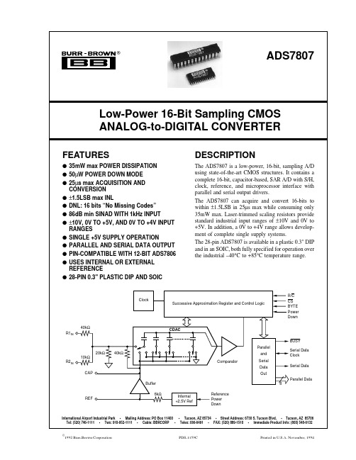
Low-Power 16-Bit Sampling CMOS ANALOG-to-DIGITAL CONVERTER
FEATURES
q 35mW max POWER DISSIPATION q 50µW POWER DOWN MODE q 25µs max ACQUISITION AND CONVERSION q ±1.5LSB max INL q DNL: 16 bits “No Missing Codes” q 86dB min SINAD WITH 1kHz INPUT q ±10V, 0V TO +5V, AND 0V TO +4V INPUT RANGES q SINGLE +5V SUPPLY OPERATION q PARALLEL AND SERIAL DATA OUTPUT q PIN-COMPATIBLE WITH 12-BIT ADS7806 q USES INTERNAL OR EXTERNAL REFERENCE q 28-PIN 0.3" PLASTIC DIP AND SOIC
Skyworks Solutions Si4844-B20 模拟调谐数字显示 AM FM SW 收音

SkyworksSolutions,Inc.•Phone[781]376-3000•Fax[781]376-3100•*********************•Si4844-B20模拟调谐数字显示 AM/FM/SW 收音机特性功能方框图⏹ 支持全球 FM 波段(64–109MHz)⏹支持全球 AM 波段(504–1750kHz)⏹支持 SW 波段(2.3–28.5MHz)⏹所有 AM/FM 地区波段可选⏹增强 FM/SW 波段覆盖范围⏹ 2 线控制接口⏹单声道/立体声和有效的电台指示器⏹数字音量支持⏹低音/高音支持⏹最少的 BOM 元件,无需手动校准⏹卓越的接收性能⏹FM 波段中国电视频道音频载波接收⏹EN55020 兼容⏹两节 AAA 电池,电源电压为 2.0 到 3.6V⏹支持宽波段铁氧体磁棒天线和空心环形天线⏹24 引脚 SSOP 封装⏹符合 RoHS该产品、其功能和/或其体系结构使用了以下一项或多项专利,以及其他正在申请或发布的国内外专利:7,127,217;7,272,373; 7,272,375; 7,321,324;7,355,476; 7,426,376; 7,471,940;7,339,503; 7,339,504.订购信息:请参阅第 21 页。
Si4844-B202SkyworksSolutions,Inc.•Phone[781]376-3000•Fax[781]376-3100•*********************•Si4844-B20SkyworksSolutions,Inc.•Phone[781]376-3000•Fax[781]376-3100•*********************• 3T ABLE OF C ONTENTSSectionPage1. Electrical Specifications . . . . . . . . . . . . . . . . . . . . . . . . . . . . . . . . . . . . . . . . . . . . . . . . . . .42. Typical Application Schematic . . . . . . . . . . . . . . . . . . . . . . . . . . . . . . . . . . . . . . . . . . . .123. Bill of Materials . . . . . . . . . . . . . . . . . . . . . . . . . . . . . . . . . . . . . . . . . . . . . . . . . . . . . . . . .134. Functional Description . . . . . . . . . . . . . . . . . . . . . . . . . . . . . . . . . . . . . . . . . . . . . . . . . . .144.1. Overview . . . . . . . . . . . . . . . . . . . . . . . . . . . . . . . . . . . . . . . . . . . . . . . . . . . . . . . . . .144.2. FM Receiver . . . . . . . . . . . . . . . . . . . . . . . . . . . . . . . . . . . . . . . . . . . . . . . . . . . . . . .154.3. AM Receiver . . . . . . . . . . . . . . . . . . . . . . . . . . . . . . . . . . . . . . . . . . . . . . . . . . . . . . .154.4. SW Receiver . . . . . . . . . . . . . . . . . . . . . . . . . . . . . . . . . . . . . . . . . . . . . . . . . . . . . . .154.5. Frequency Tuning . . . . . . . . . . . . . . . . . . . . . . . . . . . . . . . . . . . . . . . . . . . . . . . . . . .164.6. Band Select . . . . . . . . . . . . . . . . . . . . . . . . . . . . . . . . . . . . . . . . . . . . . . . . . . . . . . . .164.7. Bass and Treble . . . . . . . . . . . . . . . . . . . . . . . . . . . . . . . . . . . . . . . . . . . . . . . . . . . .164.8. Volume Control . . . . . . . . . . . . . . . . . . . . . . . . . . . . . . . . . . . . . . . . . . . . . . . . . . . . .164.9. Stereo Audio Processing . . . . . . . . . . . . . . . . . . . . . . . . . . . . . . . . . . . . . . . . . . . . . .164.10. Stereo DAC . . . . . . . . . . . . . . . . . . . . . . . . . . . . . . . . . . . . . . . . . . . . . . . . . . . . . . .174.11. Soft Mute . . . . . . . . . . . . . . . . . . . . . . . . . . . . . . . . . . . . . . . . . . . . . . . . . . . . . . . . .174.12. Reference Clock . . . . . . . . . . . . . . . . . . . . . . . . . . . . . . . . . . . . . . . . . . . . . . . . . . .174.13. Reset, Powerup, and Powerdown . . . . . . . . . . . . . . . . . . . . . . . . . . . . . . . . . . . . . .174.14. Memorizing Status . . . . . . . . . . . . . . . . . . . . . . . . . . . . . . . . . . . . . . . . . . . . . . . . .174.15. Programming with Commands . . . . . . . . . . . . . . . . . . . . . . . . . . . . . . . . . . . . . . . .175. Commands and Properties . . . . . . . . . . . . . . . . . . . . . . . . . . . . . . . . . . . . . . . . . . . . . . . .186. Pin Description: Si4844-B . . . . . . . . . . . . . . . . . . . . . . . . . . . . . . . . . . . . . . . . . . . . . . . . .207. Ordering Guide . . . . . . . . . . . . . . . . . . . . . . . . . . . . . . . . . . . . . . . . . . . . . . . . . . . . . . . . . .218. Package Outline: Si4844-B20 . . . . . . . . . . . . . . . . . . . . . . . . . . . . . . . . . . . . . . . . . . . . . .229. PCB Land Pattern: Si4844-B20 . . . . . . . . . . . . . . . . . . . . . . . . . . . . . . . . . . . . . . . . . . . . .2310. Top Marking: Si4844-B20 . . . . . . . . . . . . . . . . . . . . . . . . . . . . . . . . . . . . . . . . . . . . . . . . .2411. Additional Reference Resources . . . . . . . . . . . . . . . . . . . . . . . . . . . . . . . . . . . . . . . . . .25Document Change List . . . . . . . . . . . . . . . . . . . . . . . . . . . . . . . . . . . . . . . . . . . . . . . . . . . . .26Si4844-B204SkyworksSolutions,Inc.•Phone[781]376-3000•Fax[781]376-3100•*********************•1. Electrical SpecificationsTable 1. Recommended Operating Conditions 1,2ParameterSymbol Test ConditionMin Typ Max Unit Supply Voltage 3V DD 2— 3.6V Power Supply Powerup Rise TimeV DDRISE10——µsNotes:1.Typical values in the data sheet apply at V DD =3.3V and 25°C unless otherwise stated.2. All minimum and maximum specifications in the data sheet apply across the recommended operating conditions forminimum V DD =2.7V.3. Operation at minimum V DD is guaranteed by characterization when V DD voltage is ramped down to 2.0V. Partinitialization may become unresponsive below 2.3V.Table 2. DC Characteristics(V DD =2.7 to 3.6V, TA =–15 to 85°C)ParameterSymbolTest ConditionMinTypMaxUnitFM ModeSupply Current 1I FM —21.0—mA Supply Current 2I FMLow SNR level—21.5—mAAM/SW ModeSupply Current 1I AM—20.0—mASupplies and InterfaceV DD Powerdown CurrentI DDPD—10—µANotes:1.Specifications are guaranteed by characterization.2. LNA is automatically switched to higher current mode for optimum sensitivity in weak signal conditions.Si4844-B20SkyworksSolutions,Inc.•Phone[781]376-3000•Fax[781]376-3100•*********************• 5Figure 1.Reset TimingTable 3. Reset Timing Characteristics(V DD = 2.7 to 3.6V, TA = –15 to 85°C)ParameterSymbol Min Typ Max Unit RSTB Pulse Widtht PRST 100——µs 2-wire bus idle time after RSTB risest SDIO 100——µs 2-wire bus idle time before RSTB rises, and VDD valid time before RSTB risest SRST 100——µs RSTB low time before VDD becomes invalidt RRST——µsNotes:1.RSTB must be held low for at least 100µs after the voltage supply has been ramped up.2. RSTB needs to be asserted (pulled low) prior to the supply voltage being ramped down.RSTBVDDSDIOSCLKSi4844-B206SkyworksSolutions,Inc.•Phone[781]376-3000•Fax[781]376-3100•*********************•Table 4. 2-Wire Control Interface Characteristics 1,2,3(V DD =2.7 to 3.6V, T A =–15 to 85°C)ParameterSymbol Test ConditionMin Typ Max Unit SCLK Frequency f SCLK 0—400kHz SCLK Low Time t LOW 1.3——µs SCLK High Timet HIGH 0.6——µs SCLK Input to SDIO ↓ Setup (START)t SU:STA 0.6——µs SCLK Input to SDIO ↓ Hold (START)t HD:STA 0.6——µs SDIO Input to SCLK ↑ Setup t SU:DAT 100——ns SDIO Input to SCLK ↓ Hold 4,5t HD:DAT 0—900ns SCLK input to SDIO ↑ Setup (STOP)t SU:STO 0.6——µs STOP to START Time t BUF 1.3——µs SDIO Output Fall Timet f:OUT—250nsSDIO Input, SCLK Rise/Fall Timet f:IN t r:IN—300nsSCLK, SDIO Capacitive Loading C b ——50pF Input Filter Pulse Suppressiont SP——50nsNotes:1.When V D =0V, SCLK and SDIO are low impedance.2. When selecting 2-wire mode, the user must ensure that a 2-wire start condition (falling edge of SDIO while SCLK ishigh) does not occur within 300ns before the rising edge of RST.3. When selecting 2-wire mode, the user must ensure that SCLK is high during the rising edge of RST, and stays highuntil after the first start condition.4. The Si484x delays SDIO by a minimum of 300ns from the V IH threshold of SCLK to comply with the minimum t HD:DATspecification.5. The maximum t HD:DAT has only to be met when f SCLK =400kHz. At frequencies below 400kHz, t HD:DAT may beviolated as long as all other timing parameters are met.200.1C b1pF----------+200.1C b1pF----------+Si4844-B20SkyworksSolutions,Inc.•Phone[781]376-3000•Fax[781]376-3100•*********************• 7Figure 2.2-Wire Control Interface Read and Write Timing ParametersFigure 3.2-Wire Control Interface Read and Write Timing DiagramTable 5. FM Receiver Characteristics 1,2(V DD =2.7 to 3.6V, TA =–15 to 85°C)ParameterSymbol Test ConditionMin Typ Max Unit Input Frequencyf RF64—109MHz Sensitivity with Headphone Network 3(S+N)/N = 26 dB —2.2—µV EMFNotes:1.Additional testing information is available in “AN603: Si4822/26/27/40/44 DEMO Board Test Procedure.”Volume =maximum for all tests. Tested at RF =98.1MHz.2. To ensure proper operation and receiver performance, follow the guidelines in “AN602: Si4822/26/27/40/44 Antenna,Schematic, Layout, and Design Guidelines.” Skyworks will evaluate schematics and layouts for qualified customers.3. Frequency is 64~109MHz.4. Guaranteed by characterization.5. V EMF =1 mV.6. F MOD =1kHz, MONO, and L =R unless noted otherwise.7. ∆f =22.5kHz.8. |f 2 – f 1| > 2MHz, f 0=2x f 1 – f 2.9. B AF =300Hz to 15kHz, A-weighted.10. At L OUT and R OUT pins.11. ∆f =75 kHz.12. Tested in Digital Volume Mode.SCLK70%30%SDIO70%30%STARTSTOP t f:INt r:INt LOWt HIGHt HD:STAt SU:STA t t t SU:DATt r:INHD:DATf:IN, t f:OUTSi4844-B208SkyworksSolutions,Inc.•Phone[781]376-3000•Fax[781]376-3100•*********************•LNA Input Resistance 4,5—4—k ΩLNA Input Capacitance 4,5—5—pF AM Suppression 4,5,6,7m = 0.3—50—dB Input IP34,8—105—dBµV EMFAdjacent Channel Selectivity 4±200 kHz —50—dB Alternate Channel Selectivity 4±400 kHz —65—dB Audio Output Voltage 5,6,7,12—80—mV RMS Audio Mono S/N 5,6,7,9,10—55—dB Audio Stereo S/N 3,4,5,7,9,10—55—dB Audio Frequency Response Low 4–3dB ——30Hz Audio Frequency Response High 4–3dB 15——kHz Audio Stereo Separation 5,11—40—dB Audio THD 5,6,11—0.10.5%Audio Output Load Resistance 4,10R L Single-ended 10——k ΩAudio Output Load Capacitance 4,10C LSingle-ended——50pFTable 5. FM Receiver Characteristics 1,2 (Continued)(V DD =2.7 to 3.6V, TA =–15 to 85°C)ParameterSymbolTest ConditionMin Typ Max Unit Notes:1.Additional testing information is available in “AN603: Si4822/26/27/40/44 DEMO Board Test Procedure.”Volume =maximum for all tests. Tested at RF =98.1MHz.2. To ensure proper operation and receiver performance, follow the guidelines in “AN602: Si4822/26/27/40/44 Antenna,Schematic, Layout, and Design Guidelines.” Skyworks will evaluate schematics and layouts for qualified customers.3. Frequency is 64~109MHz.4. Guaranteed by characterization.5. V EMF =1 mV.6. F MOD =1kHz, MONO, and L =R unless noted otherwise.7. ∆f =22.5kHz.8. |f 2 – f 1| > 2MHz, f 0=2x f 1 – f 2.9. B AF =300Hz to 15kHz, A-weighted.10. At L OUT and R OUT pins.11. ∆f =75 kHz.12. Tested in Digital Volume Mode.Si4844-B20SkyworksSolutions,Inc.•Phone[781]376-3000•Fax[781]376-3100•*********************• 9Table 6. AM/SW Receiver Characteristics 1, 2(V DD = 2.7 to 3.6 V, TA = –15 to 85 °C)ParameterSymbol Test Condition Min Typ Max Unit Input Frequencyf RFMedium Wave (AM)504— 1750kHz Short Wave (SW)2.3—28.5MHz Sensitivity 3,4,5(S+N)/N = 26 dB — 30—µV EMF Large Signal Voltage Handling 5THD < 8%— 300— mV RMS Power Supply Rejection Ratio 5ΔV DD =100 mV RMS , 100 Hz— 40— dB Audio Output Voltage 3,6,8— 60— mV RMS Audio S/N 3,4,6— 55— dB Audio THD 3,6— 0.10.5%Antenna Inductance 5,7180—450µHNotes:1.Additional testing information is available in “AN603: Si4822/26/27/40/44 DEMO Board Test Procedure.”Volume =maximum for all tests. Tested at RF =520kHz and RF =6MHz.2. To ensure proper operation and receiver performance, follow the guidelines in ““AN602: Si4822/26/27/40/44 Antenna,Schematic, Layout, and Design Guidelines.” Skyworks will evaluate schematics and layouts for qualified customers.3. FMOD =1kHz, 30% modulation, 2kHz channel filter.4. B AF =300Hz to 15kHz, A-weighted.5. Guaranteed by characterization.6. V IN =5mVrms.7. Stray capacitance on antenna and board must be <10pF to achieve full tuning range at higher inductance levels.8. Tested in Digital Volume Mode.Si4844-B2010SkyworksSolutions,Inc.•Phone[781]376-3000•Fax[781]376-3100•*********************•Table 7. Reference Clock and Crystal Characteristics(V DD = 2.7 to 3.6V, T A = –15 to 85°C)ParameterSymbolTest Condition MinTypMaxUnitReference ClockXTALI Supported Reference Clock Frequencies *31.13032.76840,000kHz Reference Clock Frequency Tolerance for XTALI–100—100ppmREFCLK_PRESCALE 14095REFCLK31.13032.76834.406kHz Crystal OscillatorCrystal Oscillator Frequency —32.768—kHz Crystal Frequency Tolerance –100—100ppm Board Capacitance——3.5pF*Note: The Si4844-B20 divides the RCLK input by REFCLK_PROSCALE to obtain REFCLK. There are some RCLKfrequencies between 31.130kHz and 40MHz that are not supported. For more details, see Table 9 of “AN610: Si48xx ATDD Programming Guide.”Table 8. Thermal ConditionsParameterSymbol Min Typ Max Unit Thermal Resistance* JA —80—°C/W Ambient Temperature T A –152585°C Junction TemperatureT J——92°C*Note: Thermal resistance assumes a multi-layer PCB with the exposed pad soldered to a topside PCB pad.Si4844-B20Table 9. Absolute Maximum Ratings 1, 2Parameter Symbol Value UnitSupply Voltage V DD–0.5 to 5.8VInput Current3I IN10mAOperating Temperature T OP–40 to 95︒CStorage Temperature T STG–55 to 150︒CRF Input Level40.4V PKNotes:1.Permanent device damage may occur if the above Absolute Maximum Ratings are exceeded. Functional operationshould be restricted to the conditions as specified in the operational sections of this data sheet. Exposure beyond recommended operating conditions for extended periods may affect device reliability.2. The Si4844-B devices are high-performance RF integrated circuits with certain pins having an ESD rating of < 2kVHBM. Handling and assembly of these devices should only be done at ESD-protected workstations.3. For input pins RST, SDIO, SCLK, XTALO, XTALI, BAND, TUNE2, TUNE1, IRQ, and LNA_EN.4. At RF input pins, FMI, and AMI.Si4844-B202. Typical Application SchematicNotes:1.Place C4 close to V DD2 and DBYP pins.2. All grounds connect directly to GND plane on PCB.3. Pin 6 and 7 leave floating.4. To ensure proper operation and receiver performance, follow the guidelines in “AN602: Si4822/26/27/40/44 Antenna,Schematic, Layout, and Design Guidelines.” Skyworks will evaluate the schematics and layouts for qualified customers.5. Pin 8 connects to the FM antenna interface and pin 12 connects to the AM antenna interface.6. Place Si484x as close as possible to antenna jack and keep the FMI and AMI traces as short as possible.7. Recommend keeping the AM ferrite loop antenna at least 5cm away from the Si4844-B.8. Keep the AM ferrite loot antenna away from the MCU, audio amplifier, and other circuits which have AM interference.9. Place the transformer T1 away from any sources of interference and even away from the I/O signals of the Si4844-B.Si4844-B20 3. Bill of MaterialsTable 10. Si4844-B20 Bill of MaterialsComponent(s)Value/Description Supplier C1Reset capacitor 0.1µF, ±20%, Z5U/X7R MurataC4Supply bypass capacitor, 0.1µF, ±20%, Z5U/X7R MurataC5Coupling capacitor, 0.47µF, ±20%, Z5U/X7R MurataB1Ferrite bead 2.5k/100MHz MurataVR1Variable resistor (POT), 100k, ±10% KennonU1Si4844-B AM/FM/SW Analog Tune Digital Display Radio Tuner SkyworksANT1Ferrite stick,180–450μH JiaxinOptional ComponentsC2, C3Crystal load capacitors, 22pF, ±5%, COGVenkel(Optional: for crystal oscillator option)Y132.768kHz crystal (Optional: for crystal oscillator option)Epson or equivalentANT2Air loop antenna, 10-20μH variousS1Band switch Any, depends on customerR1Resistor, 203k, ±1%VenkelR2Resistor, 50k, ±1%VenkelR3Resistor, 180k, ±1%VenkelR4Resistor, 67k, ±1%VenkelSi4844-B204. Functional DescriptionFigure4.Si4844-B Functional Block Diagram4.1. OverviewThe Si4844-B is the analog-tuned digital-display digital CMOS AM/FM/SW radio receiver IC that integrates the complete receiver function from antenna input to audio output. Working with an external MCU with LCD/LED driver, Si4844-B can output the AM/FM/SW frequencies, band, Bass/Treble and stereo/mono information to display on LCD/LED, while using a simple potentiometer at the front end for analog-tune. Leveraging Skyworks' proven and patented digital low intermediate frequency (low-IF) receiver architecture, the Si4844-B delivers superior RF performance and interference rejection in AM, FM and SW bands. The Si4844-B is pin-to-pin compatible with the current Si484x-A tuning. The Si4844-B shares the advanced features of the Si484x-A and can support a wider range of FM and SW bands. It also supports China TV channels and audio reception in the FM band. The superior control algorithm integrated in Si4844-B provides an easy and reliable control interface while eliminating all the manually tuned external components used in traditional solutions.Like other successful audio products from Skyworks, Si4844-B offers unmatched integration and PCB space savings with minimum external components and small board area on a single side PCB. The high integration and complete system production test simplifies design-in, increases system quality, and improves manufacturability. The receiver has very low power consumption, runs off two AAA batteries, and delivers the performance benefits of high performance digital radio experience with digital display to the legacy analog-tuned radio market.The Si4844-B provides good flexibility in using the chip. The frequency range of FM/AM/SW bands, mono/stereo threshold, de-emphasis value, AM tuning step, AM soft mute level/rate, and Bass/Treble can be either configured by the MCU or by using external hardware to make a selection. The reference clock of the FM tuner can be provided either by the crystal or by the host MCU within tolerance.Si4844-B also has flexibility in selecting bands and configuring band properties, enabling masked Host MCU for multiple projects, and reducing the cost of development. Four tuning preferences are available tomeet different tuning preference requirements.4.2. FM ReceiverThe Si4844-B integrates a low noise amplifier(LNA) supporting the worldwide FM broadcast band (64to 109MHz) and the TV audio stations within the fre quency range in China are also supported. The FM band can also be configured to be a wider range such as 64–108 MHz in one band.Pre-emphasis and de-emphasis is a technique used by FM broadcasters to improve the signal-to-noise ratio of FM receivers by reducing the effects of high frequency interference and noise. When the FM signal is transmitted, a pre-emphasis filter is applied to accentuate the high audio frequencies. All FM receivers incorporate a de-emphasis filter which attenuates high frequencies to restore a flat frequency response. Two time constants are used in various regions. The de-emphasis time constant can be chosen to be 50 or 75μs. Refer to “AN602: Si4822/26/27/40/44 Antenna, Schematic, Layout, and Design Guidelines.”The Si4844-B also has advanced stereo blending that employs adaptive noise suppression. As a signal quality degrades, the Si4844-B gradually combines the stereo left and right audio channels to a mono audio signal to maintain optimum sound fidelity under varying reception conditions. The Si4844-B can output a stereo signal to MCU with LCD/LED driver to display on the LCD/LED so that the user can easily discern the signal quality.The stereo on signal is defined using both RSSI and the Left and Right separation levels as these two specifications are the primary factors for stereo listening. The criteria can be set between two conditions: the Left and Right channels are separated by more than 6dB with RSSI at >20dB or Left and Right channels are separated by more than 12dB with RSSI at >28dB. The selection can be set up using different values of the external resistor or configured by the host MCU. Refer to “AN602: Si4822/26/27/40/44 Antenna, Schematic, Layout, and Design Guidelines.”The user can also refer to the “AN610: Si48xx ATDD Programming Guide” for those who want to configure the value by host MCU.4.3. AM ReceiverThe highly integrated Si4844-B supports worldwide AM band reception from 504 to 1750kHz with five sub-bands using a digital low-IF architecture with a minimum number of external components and no manual alignment required. This patented architecture allows for high-precision filtering, offering excellent selectivity and SNR with minimum variation across the AM band. Similar to the FM receiver, the Si4844-B optimizes sensitivity and rejection of strong interferers, allowing better reception of weak stations.To offer maximum flexibility, the receiver supports a wide range of ferrite loop sticks from 180–450μH. An air loop antenna is supported by using a transformer to increase the effective inductance from the air loop. Using a 1:5 turn ratio inductor, the inductance is increased by 25 times and easily supports all typical AM air loop antennas, which generally vary between 10 and 20μH.A 9, 10kHz tuning step can be chosen by the external resistor or host MCU according to the different regions, and AM soft mute level can be programmed by the host MCU to have different tuning experiences. One of the AM bands can be configured as a universal AM band that simultaneously supports 9kHz and 10kHz channel spaces for all regional AM standards worldwide. Refer to “AN610: Si48xx ATDD Programming Guide” and “AN602: Si4822/26/27/40/44 Antenna, Schematic, Layout, and Design Guidelines”for more details.4.4. SW ReceiverThe Si4844-B supports short wave band receptions from 2.3 to 28.5MHz in 5kHz step size increments. It can also be configured to have a wide SW band that can be used in SW radio with 1 or 2 SW banks. Si4844-B supports extensive short wave features such as minimal discrete components and no factory adjustments. The Si4844 supports using the FM antenna to capture short wave signals. Refer to “AN610: Si48xx ATDD Programming Guide”and “AN602: Si4822/26/27/40/44 Antenna, Schematic, Layout, and Design Guidelines”for more details.4.5. Frequency TuningA valid channel can be found by tuning the potentiometer that is connected to the TUNE1 and TUNE2 pin of the Si4844-B chip.To offer easy tuning, the Si4844-B also outputs the tuned information to the MCU with LCD/LED driver to display. It will light up the icon on display if the RF signal quality passes a certain threshold when tuned to a valid station. Multiple tuning preferences are available. The user can choose to have the best performance (volume, stereo/mono effect) only at the exact channel, or the best performance in a larger range. Refer to "AN610: Si48xx ATDD Programming Guide" for more details. 4.6. Band SelectThe Si4844-B supports worldwide AM band with five sub-bands, US/Europe/Japan/China FM band with five sub-bands, and SW band with 16 sub-bands. Si4844-B provides the flexibility to configure the band and band properties at either the MCU side or the Tuner side, enabling masked MCU for multiple projects. For details on band selection, refer to “AN602: Si4822/26/27/40/44 Antenna, Schematic, Layout, and Design Guidelines”and "AN610: Si48xx ATDD Programming Guide".4.7. Bass and TrebleThe Si4844-B further supports Bass/Treble tone control for superior sound quality. The Si4844-B can be set to be default normal, or programmed by the host MCU I2C-compatible 2-wire mode. FM has nine levels Bass/Treble effect and AM/SW has seven levels Bass/Treble effect. For further configuration details, refer to "AN610: Si48xx ATDD Programming Guide." 4.8. Volume ControlThe Si4844-B not only allows users to use the traditional PVR wheel volume control through an external speaker amplifier, it also supports digital volume control programmed by the host MCU. Si4844-B can be programmed to be Bass/Treble mode only or digital volume mode only; it can also be programmed to have the digital volume coexist with Bass/Treble in two modes. Refer to "AN610: Si48xx ATDD Programming Guide" and “AN602: Si4822/26/27/40/44 Antenna, Schematic, Layout, and Design Guidelines” for more details.4.9. Stereo Audio ProcessingThe output of the FM demodulator is a stereo multiplexed (MPX) signal. The MPX standard was developed in 1961, and is used worldwide. Today's MPX signal format consists of left + right (L+R) audio, left – right (L–R) audio, a 19kHz pilot tone.Figure5.MPX Signal Spectrum4.9.1. Stereo DecoderThe Si4844-B's integrated stereo decoder automatically decodes the MPX signal using DSP techniques. The 0 to 15kHz (L+R) signal is the mono output of the FM tuner. Stereo is generated from the (L+R), (L–R), and a 19kHz pilot tone. The pilot tone is used as a reference to recover the (L–R) signal. Output left and right channels are obtained by adding and subtracting the (L+R) and (L–R) signals respectively.4.9.2. Stereo-Mono BlendingAdaptive noise suppression is employed to gradually combine the stereo left and right audio channels to a mono (L+R) audio signal as the signal quality degrades to maintain optimum sound fidelity under varying reception conditions. Three metrics, received signal strength indicator (RSSI), signal-to-noise ratio (SNR), and multipath interference, are monitored simultaneously in forcing a blend from stereo to mono. The metric which reflects the minimum signal quality takes precedence and the signal is blended appropriately.All three metrics have programmable stereo/mono thresholds and attack/release rates. If a metric falls below its mono threshold, the signal is blended from stereo to full mono. If all metrics are above their respective stereo thresholds, then no action is taken to blend the signal. If a metric falls between its mono and stereo thresholds, then the signal is blended to the level proportional to the metric’s value between its mono and stereo thresholds, with an associated attack and release rate.0575338231915Frequency (kHz)ModulationLevel4.10. Stereo DACHigh-fidelity stereo digital-to-analog converters (DACs) drive analog audio signals onto the LOUT and ROUT pins. The audio output may be muted.4.11. Soft MuteThe soft mute feature is available to attenuate the audio outputs and minimize audible noise in very weak signal conditions. An advanced algorithm is implemented to get a better analog tuning experience. The soft mute feature is triggered by the SNR metric. The SNR threshold for activating soft mute is programmable, as are soft mute attenuation levels and attack and decay rates.4.12. Reference ClockThe Si4844-B supports programmable RCLK input (to XTALI pin) with the spec listed in Table7. It can be shared with the host MCU to save extra crystal.An onboard crystal oscillator is available to generate the 32.768kHz reference when an external crystal and load capacitors are provided. Refer to "AN602: Si4822/26/27/40/44 Antenna, Schematic, Layout, and Design Guidelines" for more details.4.13. Reset, Powerup, and Powerdown Setting the RSTB pin low will disable analog and digital circuitry, reset the registers to their default settings, and disable the bus. Setting the RSTB pin high will bring the device out of reset.Figure1 shows typical reset, startup, and shutdown timings for the Si4844-B. RSTB must be held low (asserted) during any power supply transitions and kept asserted as specified in Figure1 after the power supplies are ramped up and stable. Failure to assert RSTB as indicated here may cause the device to malfunction and may result in permanent device damage.A powerdown mode is available to reduce power consumption when the part is idle. Putting the device in powerdown mode will disable analog and digital circuitry while keeping the bus active.4.14. Memorizing StatusThe Si4844-B provides the feature to memorize status from the last power down with a simple design on PCB, including frequency of the FM/AM/SW station. Refer to “AN602: Si4822/26/27/40/44 Antenna, Schematic, Layout, and Design Guidelines”for details.4.15. Programming with CommandsTo ease development time and offer maximum customization, the Si4844-B provides a simple yet powerful software interface to program the receiver. The device is programmed using commands, arguments, properties, and responses.To perform an action, the user writes a command byte and associated arguments, causing the chip to execute the given command. Commands control an action such as powerup the device, shut down the device, or get the current tuned frequency. Arguments are specific to a given command and are used to modify the command. Properties are a special command argument used to modify the default chip operation and are generally configured immediately after powerup. Examples of properties are de-emphasis and soft mute attenuation threshold.Responses provide the user information and are echoed after a command and associated arguments are issued. All commands provide a 1-byte status update, indicating interrupt and clear-to-send status information. For a detailed description of the commands and properties for the Si4844-B, see "AN610: Si48xx ATDD Programming Guide."。
电子密码锁中英文对照外文翻译文献
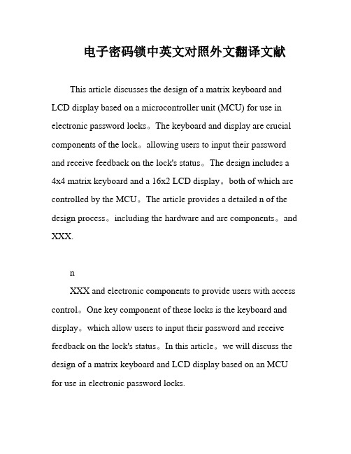
电子密码锁中英文对照外文翻译文献This article discusses the design of a matrix keyboard and LCD display based on a microcontroller unit (MCU) for use in electronic password locks。
The keyboard and display are crucial components of the lock。
allowing users to input their password and receive feedback on the lock's status。
The design includes a 4x4 matrix keyboard and a 16x2 LCD display。
both of which are controlled by the MCU。
The article provides a detailed n of the design process。
including the hardware and are components。
and XXX.nXXX and electronic components to provide users with access control。
One key component of these locks is the keyboard and display。
which allow users to input their password and receive feedback on the lock's status。
In this article。
we will discuss the design of a matrix keyboard and LCD display based on an MCU for use in electronic password locks.DesignThe design of the matrix keyboard and LCD display is based on an MCU。
ICL7116中文资料

Thermal Information
Thermal Resistance (Typical, Note 2) θJA (oC/W) PDIP Package . . . . . . . . . . . . . . . . . . . . . . . . . . . . . 50 MQFP Package . . . . . . . . . . . . . . . . . . . . . . . . . . . . 80 Maximum Junction Temperature . . . . . . . . . . . . . . . . . . . . . . . 150oC Maximum Storage Temperature Range . . . . . . . . . .-65oC to 150oC Maximum Lead Temperature (Soldering 10s) . . . . . . . . . . . . . 300oC (MQFP - Lead Tips Only)
Ordering Information
PART NUMBER ICL7116CPL ICL7116CM44 ICL7117CPL TEMP. RANGE (oC) 0 to 70 0 to 70 0 to 70 PACKAGE 40 Ld PDIP 44 Ld MQFP 40 Ld PDIP PKG. NO. E40.6 Q44.10x10 E40.6
元器件交易网
ICL7116, ICL7117
January 1998
3 1/2 Digit, LCD/LED Dis
Description
The Intersil ICL7116 and ICL7117 are high performance, low power, 31/2 digit, A/D converters. Included are seven segment decoders, display drivers, a reference, and a clock. The ICL7116 is designed to interface with a liquid crystal display (LCD) and includes a multiplexed backplane drive. The ICL7117 will directly drive an instrument size, light emitting diode (LED) display. The ICL7116 and ICL7117 have all of the features of the ICL7106 and ICL7107 with the addition of a HOLD Reading input. With this input, it is possible to make a measurement and retain the value on the display indefinitely. To make room for this feature the reference low input has been connected to Common internally rather than being fully differential. These circuits retain the accuracy, versatility, and true economy of the ICL7106 and ICL7107. They feature auto-zero to less than 10µV, zero drift of less than 1µV/oC, input bias current of 10pA maximum, and roll over error of less than one count. The versatility of true differential input is of particular advantage when measuring load cells, strain gauges and other bridge-type transducers. And finally, the true economy of single power supply operation (ICL7116) enables a high performance panel meter to be built with the addition of only eleven passive components and a display.
筋膜枪专用mos管AP15N10D_15A_100V_TO-252
TSTG
Storage Temperature Range
-55 to 150
TJ
Operating Junction Temperature Range
-55 to 150
RθJA
Thermal Resistance Junction-ambient 1
62
RθJC
Thermal Resistance Junction-Case1
Marking
Qty(PCS)
AP15N10D
TO-252
AP15N10D XXX YYYY
2500
Absolute Maximum Ratings (TC=25℃unless otherwise noted)
Symbol
Parameter
Rating
VDS VGS ID@TC=25℃ ID@TC=100℃ ID@TA=25℃ ID@TA=70℃ IDM
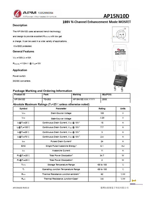
Description
AP15N10D
100V N-Channel Enhancement Mode MOSFET
The AP15N10D uses advanced trench technology and design to provide excellent RDS(ON) with low gat e charge. It can be used in a wide variety of applications. It is ESD protested.
2
AP15N10D RVE3.0
臺灣永源微電子科技有限公司
Typical Characteristics
25 20 15 10
AP15N10D
- 1、下载文档前请自行甄别文档内容的完整性,平台不提供额外的编辑、内容补充、找答案等附加服务。
- 2、"仅部分预览"的文档,不可在线预览部分如存在完整性等问题,可反馈申请退款(可完整预览的文档不适用该条件!)。
- 3、如文档侵犯您的权益,请联系客服反馈,我们会尽快为您处理(人工客服工作时间:9:00-18:30)。
LOW-POWER DA-CONVERTERS FOR DISPLAY APPLICATIONS USING STEPWISECHARGING AND CHARGE RECOVERYC.Saas,A.Wr´o blewski and J.A.NossekMunich University of Technology,Institute for Circuit Theory and Signal processingArcisstr.16,D-80298M¨u nchenchsa@nws.ei.tum.deABSTRACTThe application of adiabatic switching for driving high capaci-tive loads encountered on the column lines offlat panel displays is investigated.A new digital-to-analog converter using stepwise charging is proposed to minimize power dissipation.Most of the energy stored on the charged column lines can be recovered.The proposed DAC is capable of driving the high capacitive load with-out any bias current.Therefore,both dynamic and static power dissipation are reduced to a large extent.Simulations of the pro-posed architecture are compared with a lower bound for the power dissipation based on a simplified model of a conventional imple-mentation demonstrating the potential of the new approach.1.INTRODUCTIONIn applications where a back-light panel is not always required, the control and driving circuits of aflat panel display consume a significant part of the dissipated power[8].It has been shown[5], [9]that adiabatic switching provides promising results when used for high capacitive,simple logic and low speed applications.All of these requirements are fulfilled when driving column lines in a flat panel display.The investigations presented in this paper are applicable to most kinds offlat panel displays regardless of the ac-tual display element.Nevertheless,the obtained results are based on models for active matrix LCD and OLED displays.The principle of stepwise charging for driving displays has already been presented in[2],but its use was limited to the polarity change necessary in a LCD display.In this work stepwise charging is ap-plied to actually charge the capacitance to the desired voltage level. There are two distinct problems present in this application.First of all the row lines have to be charged to afixed supply voltage to open the pass transistors of a pixel row.This is comparable to driving the output pad of an integrated circuit[5,6]and will not be covered in this paper.Second,the charging of the column lines is a difficult task as a certain voltage level depending on the actual image content has to be reached.This voltage level represents the brightness of the pixel and therefore has to be maintained accu-rately.In Section2a conventional approach is described,which serves as a reference for comparison,while in Section3the new approach is outlined.In Section4simulation results are presented followed by a conclusive Section5.Stepwise chargingStepwise charging is a method to reduce the power dissipated dur-ing the charging of a capacitance.The voltage ramps required for adiabatic switching are approximated by a number of rectangular steps.When a linear capacitance C is charged by a voltage step U the dissipated energy isE=12CU2.(1)Using stepwise charging the voltage step is only UN,where N is the number of steps used.Of course this step occurs N times,but it can easily be calculated that this leads to a power reduction of 1Nwith respect to a full voltage swingE stepwise=N12C(UN)2=1NE.(2) Therefore the higher the number of steps the bigger the power sav-ings.The calculations made here are only valid if the time between the steps is long enough for the system to settle.Stepwise charg-ing involves like all adiabatic techniques a trade off between power and speed.2.CONVENTIONAL APPROACHThe architecture of a conventional column driver is depicted in Fig.1.It consists of a single DAC,an analog shift register ASR and analog drivers for each line.The digital pixel stream is decoded for the DAC in the decoder L.In this structure the DAC consumes only a small part of the area and the power.A lot of effort has to be made to realize the highly precise analog shift register.The main source for energy dissipation are the drivers.Fig.1.Architecture of a conventional column driverPower estimationDue to a large number of available operational amplifier designs simulations have not been performed on a reference design up tonow.Instead,we estimated the dissipated power by means of ana-lytical formulae.In the line driver there are two main sources for energy dissipation.The first one is rather obvious and results from the charging and discharging of the line capacitance.As there is no charge recovery the energy dissipated during one cycle is given byE dyn =CU 2(3)where C is the capacitance of the column line and U is the voltagedifference between the off level and the desired pixel value.All other parasitic capacitances can be considered to be small with regards to C and have been neglected.The second one results from the bias currents in the operational amplifiers.Their value can be estimated from the specifications regarding load and performance.For a Miller OTA the overdrive voltage is given by [7]u overdrive =SRGBW.The slew rate SR and the gain band width GBW are given by the performance requirements.The second pole has to be located at p 2=3·GBW to fulfill stability criteria for a full feedback configuration.The resulting transconductance g m is given by:g m =3·GBW ·C L .To obtain this transconductance a bias current ofI BIAS =g m ·u overdrive(4)is needed.Please note,that only the bias current for the last stage has been taken into account and the significantly smaller current for the input stage has been neglected.Both,P BIAS and P dyn are based on ideal models and therefore don’t take any leakage or resistive losses into account.All simpli-fications and assumptions made reduce the calculated power con-sumption.Therefore P BIAS and P dyn can be regarded as a lower bound for the dissipated energy.The calculated values for the re-garded environment can be seen in Table 1.V oltage4.2V number of rows 1200P dyn (010)2.88e −05W display-height 20cm P dyn (110)2.60e −04W line capacitance 1fFµm [4]P dyn (111)3.53e −04W image refresh 60Hz P Bias 4.80e −04Wrow clock100kHzTable 1.given and calculated values for the used environment3.PROPOSED APPROACHThe proposed architecture (Fig.2)implements as many compo-nents as possible in the digital domain as to minimize the effort in power and area for analog components.The presented DA con-verter is capable of driving the lines and therefore there is no need for analog line drivers.The digital registers consume significantly less energy than the analog counterpart.Although the new logic L is slightly more complicated and one DAC is needed at each line,the power consumption is negligible with respect to the bias currents of the conventional line drivers.Fig.2.Architecture of the proposed column driverTo keep the explanation simple only a 3bit DAC is evaluated,which is on no account a limitation.Improvements like cascading can be applied by introducing mere modifications to the logic L .Therefore it should be no problem to extend bit deptheven further on.Nevertheless when,as in most cases,more bits are required a multi stage hybrid DAC might be useful.Evaluations regarding this topic are currently going on.3.1.Stepwise charging with fixed reference voltageslreference voltage generationlocal driverFig.3.Schematic for FR-DACThe basic idea of stepwise charging is demonstrated on the ex-ample of the fixed reference DA converter (FR-DAC)in Fig.3.Itd 1d 2d 3d 4d 5d 6d 7Fig.4.Input bits for a digital value of 100a)charging b)discharg-ing of CR-DACis able to reduce dissipated energy and maintain high accuracy at the same time.To obtain the FR-DAC only small modifications to a standard resistor string DA converter is needed.Each line is driven by one FR-DAC in which the dynamic losses due to capaci-tive load are dissipated.Stepwise charging is realized by applying a digital control signal,which will switch the output to the next higher value for each time step until the desired voltage level is reached.An example for the control signal can be seen in Fig.4a.They are calculated by the logic block L from the digital pixel value obtained from the register.A similar decoder is also present in the conventional DAC.Both decoders have as many outputs as the DAC can produce voltage levels.In the FR-DAC however,in-stead of setting the pin corresponding to the desired voltage level to high all pins with lower values will be set to high one after an-other.This will result in a stepwise charging of the output up to the desired voltage level.To benefit from the possible power sav-ings it is important to ensure that an intermediate voltage level is almost reached before the next clock edge.The clock used in this domain of the circuit will be called DAC clock.It has to be at least N times faster than the row clock of the display where N is the number of voltage levels.This does not present any problems as the row clock is usually not time critical.The DAC clock can be derived from the pixel clock.This solution will generate an area overhead by introducing a DA converter for every line.The area overhead is reduced by avoid-ing the analog shift register and the output drivers at each column.Despite the area overhead there is a significant reduction in power consumption.The reduction is only achieved during charging of the output.All energy stored on the charged output capacitor is lost during discharging.No stepwise discharging has to be applied,a simple reset switch is enough to realize distinct voltage peaks.In certain cases some of the energy can be saved by not resetting the output,but starting at the voltage level of the last pixel.Most of the time this is not possible due to pixel inversion.3.2.Charge recovery during dischargingA significant part of the energy on the line can be recovered by ap-plying some technique of charge recovery.In several publications [1,3]charge recovery using resonant RLC circuits in a flat panel display is limited to recover energy during the change of polariza-tion.In this work large capacitors are used to temporarily deliver energy and to recover the charge when driving analog output volt-ages.In Fig.5a the schematic of the reference voltage generation cir-lreference voltage generationlocal driverFig.5.Schematic for CR-DACcuit for the charge recovery DA converter (CR-DAC)is shown.There is one large source capacitor C s per reference voltage.It is charged by reference voltage sources to the appropriate voltage level during the reset period.Afterwards the whole DAC is pow-ered from the capacitors.Connecting the line capacitance C l to the source capacitor C s 1−6will result in a voltage equalization.The line voltage will increase whereas the voltage of the source capacitor slightly decrease.As the resulting voltage level U is given byU =C s C l +C s U s +C lC l +C sU l(5)the source capacitances have to be large.The error of the line volt-age with respect to the desired voltage depends on the size of C s .Please note,that this is a systematic offset error which can easily be compensated by calibration.As there is only one reference volt-age generator per display,the source capacitors could be realized as external elements.During charging of the output the CR-DAC works like the FR-DAC.The reference voltages are connected one after another to the output thus charging it up in small steps.During discharging most of the energy can be transferred back onto the C s .The output is discharged stepwise by connecting the load to the appropriate reference voltages.Thus every clock cycle the output voltage isdecreased by UN.When the output is connected to the next lower reference voltage level some of the charge is transfered back to C s and the corresponding reference voltage across C s is nearly restor-ing the initial value.Of course,there can be no energy transferred to the highest voltage level.The amount of energy taken from this reference voltage is prorated on the charging and discharging of the single steps.In the following reset the losses are compen-sated by connecting C s to the appropriate reference voltage.It canFig.6.Output voltage and reference voltages of the CR-DAC easily be calculated that in theory all but the highest source capac-itors C smax recover charge up to their original voltage value.The energy which has been dissipated and thus has to be replaced in C smax is given byE smax=UN·U max·C l(6)where U max is the voltage the line was charged up to and C smax the corresponding source capacitor.Currently research is done on the realization of low impedance reference voltage sources.As afinal solution has not been chosen up to now power dissipation in the reference voltage generation has not been considered.Using the precharge already present on the line is investigated.We do not expect results in power dissipation to change significantly, as most of the charge is recovered in the CR-DAC.Anyhow this would only be applicable if it is compatible to the pixel inversion scheme.4.SIMULATION RESULTSFigure6shows the simulated output transition for a pixel value of 111.The operation of the circuit can clearly be observed.Step-wise charging is working as expected.The voltage drop on the reference voltages is very small.The simulation results given in table4demonstrate a significant reduction in energy dissipation. For a value of111the power consumption is reduced to only5%. As expected the dominant part of power dissipation occurs on the reference voltage corresponding to the desired output level as there is no charge recovery.The dissipated energy scales linearly with the pixel value.Therefore P dyn benefits more from the reduced voltage for lower pixel values,but even in the extreme case,where the pixel value is000,there is still a reduction to9%due to the reduction of bias currents.5.CONCLUSIONIn this work the concept of stepwise charging has been applied to thefield of display drivers.A novel digital analog converter has been proposed.It is capable of recovering most of the chargepixel value010110111P smax 1.44e-05 4.32e-05 5.04e-05P V1[W]-1.03e-08-1.51e-07-1.51e-07P V2[W] 1.45e-05 2.26e-08 2.27e-08P V3[W]-4.31e-10-1.16e-09-1.36e-09P V4[W]-4.55e-10-8.00e-08-9.29e-08P V5[W]8.61e-10 6.75e-07-4.71e-08P V6[W] 1.15e-09 4.35e-059.07e-07P V7[W]-8.72e-10-7.80e-10 5.06e-05P ges[W] 1.45e-05 4.39e-05 5.13e-05Table2.Simulated power dissipations for the CR-DAC stored on the line capacitance during discharge and can be directly connected to the line thus avoiding the need for power intensive operational amplifiers.The resulting new architecture may lead to some area overhead but consumes significantly less energy. Further work has to be done on increasing the bit depth by apply-ing a second DAC stage.Probably this second stage is also capable of correcting the small error introduced by the CR-DAC.Different realisations of low impedance reference sources have to be evalu-ated.Overall this concept seems to be very promising to dramatically reduce power consumption offlat panel display drivers with an acceptable overhead.6.REFERENCES[1] F.Devisch,J.Stiens,R.V ounckx,and M.Kuijk.Low PowerRLC-Resonant Method for Driving Liquid-Crystal Displays.SID DIGEST,pages594–597,2000.[2] A.Erhart and D.McCartney.Charge-Conservation Implemen-tation in an Ultra-Low-Power AMLCD Column Dirver Utiliz-ing Pixel Inversion.SID DIGEST,pages23–26,1997.[3]J.H.Kim,Y.C.Sung,D.U.Lee,and O.K.Kwon.Low-PowerData Driver for TFT-LCDs Using Energy Recovery Circuit.SID DIGEST,pages698–701,2002.[4]Ernst Lueder.Liquid Crystal Displays.2001.[5] C.Saas and J.A.Nossek.Resonant Multistage Charging ofDominant Capacitances.PATMOS,2002.[6] C.Saas,A.Schlaffer,and J.A.Nossek.An adiabatic multistage driver.ECCTD,2001.[7]W.Sansen and ker.Design of Analog Integrated Circuitsand Systems.1994.[8]M.Senda,Y.Tsutsui,R.Yokohama,K.Yoneda,S.Mat-sumoto,and A.Sasaki.Ultra-Low-Power Polysilicon AMLCD with Full Integration.SID DIGEST,pages790–793, 2002.[9] B.V oss and M.Glesner.Adiabatic Charging of Long Inter-connects.ICECS,pages853–838,2000.。