SP3D学习笔记(注释)word版本
高二化学苏教版选修3素材互动课堂专题4第一单元分子构型与物质的性质Word版含解析

互动课堂疏导引导知识点1:分子的空间构型1.杂化和杂化轨道杂化是指在形成分子时,由于原子的相互影响,若干不同类型能量相近的原子轨道混合起来,重新组合成一组新轨道。
这种轨道重新组合的过程叫做杂化,所形成的新轨道就称为杂化轨道。
2.杂化过程及杂化轨道类型(1)杂化过程杂化轨道理论认为在形成分子时,通常存在激发、杂化和轨道重叠等过程。
(2)杂化轨道的类型对于非过渡元素,由于ns、np能级比较接近,往往采用sp型杂化。
对于过渡元素,(n-1)d、ns、np能级比较接近,常常采用dsp型杂化。
sp型杂化,又分为sp杂化、sp2杂化、sp3杂化。
dsp型杂化分为dsp2、dsp3、d2sp2等。
3.典型分子的杂化过程及立体构型(1)sp型杂化:一个ns轨道和一个np轨道间的杂化,杂化后得到两个sp杂化轨道,且杂化轨道间的夹角是180°,呈直线形。
如BeCl2、CH≡CH分子的形成。
①BeCl2:Be原子的电子排布为1s22s2,从表面上看Be原子似乎不能形成共价键,但是在激发状态下,Be的一个2s电子可以进入2p轨道,经过杂化形成2个sp杂化轨道,与氯原子的具有一个单电子的3p轨道重叠形成两个σ键。
由于杂化轨道间的夹角为180°,所以形成的BeCl2分子的空间结构是直线形的。
请参看过程图:Be原子sp杂化过程两个sp杂化轨道BeCl2分子中σ键②CH≡CH:碳原子的电子排布为1s22s22p2,在形成CH≡CH分子时,碳原子2s轨道上的一个电子受激发跃迁到2p空轨道,一个2s轨道和一个2p轨道杂化形成2个sp杂化轨道,且各有一个单电子,呈直线形;剩余的2个各具有1个电子的2p轨道未参加杂化,则垂直于两个sp杂化轨道形成的直线,每个碳原子的两个sp杂化轨道分别与一个氢原子的1s轨道形成1个σ键,各自剩余的1个sp杂化轨道相互形成一个σ键,而各自没有参与杂化的2个2p轨道以垂直于前面3个σ键所在的直线“肩并肩”形成2个π键,从而形成CH≡CH分子。
高一化学《杂化轨道理论》知识要点精华

高一化学《杂化轨道理论》知识要点精华1.杂化轨道理论(1)杂化轨道理论要点为了解释分子或离子的立体结构,鲍林以量子力学为基础提出了杂化轨道理论。
我们不妨先以甲烷为例说明杂化轨道理论的出发点;甲烷分子实测的和VSEPR模型预测的立体结构都是正四面体。
若认为CH4里的中心原子碳的4个价电子层原子轨道一一2s和2 px,2py,2pz分别跟4个氛原子的Is原子轨道重叠形成。
键,无法解样甲烷的4个C-H 键是等同的,因为碳原子的3个2p轨道是相互垂直,而2s轨道是球形的.鲍林假没,甲烷的中心原子一一碳原子一一在形成化学键时,4个价电子层原子轨道并不维持原来的形状,而是发生所谓“杂化”,得到4个等同的轨道,总称sp3杂化轨道。
除sp3杂化,还有两种由s轨道和p轨道杂化的类型,一种是1个s轨道和2个p轨道杂化,杂化后得到平面三角形分布的3个轨道,总称sp2杂化轨道;另一种是1个s轨道和 1个P轨道杂化,杂化后得到呈直线分布的2个轨道,总称sp杂化轨道。
图2-6画出了sp3、s P2和sp三种杂化轨道在空间的排布。
在该图最右边画出了未参与sp2杂化和sp杂化的剩余p轨道与杂化轨道的空间关系一一未参与sp2杂化的1个p轨道垂直于杂化轨道形成的平面;未参与sp杂化的2个p轨道与sp杂化轨道形成的直线呈正交关系(即相互垂直)。
注意:杂化轨道总是用于构建分子的。
轨道,未参与杂化的p轨道才能用于构建n键,在学习杂化轨道理论时既要掌握杂化轨道的空间分布,也要掌握未杂化的p轨道与杂化轨道的空间关系,否则难以全面掌握分子的化学键结构。
f...芸厂……二IIIHS诿化Q+00(=>OO=—O—讨论分子中的中心原子的杂化轨道类型的基础是预先知道它的立体结构。
如果没有实验数据,可以借助VSEPR模型对分子的立体结构作出预沉这是我们为什么在讨论杂化轨道理论之前先讨论VSEPR的原因。
特别要注意的是.如果分子的中心原子上有采取。
SmartPlant3D_SP3D软件基础操作
SmartPlant3D_SP3D软件基础操作SmartMarine 3DCommon Applications LabsVersion 7.3October 2007CopyrightCopyright ? 2007 Intergraph Corporation. All Rights Reserved. Including software, file formats, and audiovisual displays; may be used pursuant to applicable software license agreement; contains confidential and proprietary information of Intergraph and/or third parties which is protected by copyright law, trade secret law, and international treaty, and may not be provided or otherwise made available without proper authorization.Restricted Rights LegendUse, duplication, or disclosure by the Government is subject to restrictions as set forth in subparagraph (c) of the Contractor Rights in Technical Data clause at DFARS 252.227-7013, subparagraph (b) of the Rights in Computer Software or Computer Software Documentation clause at DFARS 252.227-7014, subparagraphs (b)(1) and (2) of the License clause at DFARS 252.227-7015, or subparagraphs (c) (1) and (2) of Commercial Computer Software--Restricted Rights at 48 CFR 52.227-19, as applicable. Unpublished---rights reserved under the copyright laws of the United States. Intergraph Corporation Huntsville, Alabama 35894-0001Warranties and LiabilitiesAll warranties given by Intergraph Corporation aboutequipment or software are set forth in your purchase contract, and nothing stated in, or implied by, this document or its contents shall be considered or deemed a modification or amendment of such warranties. Intergraph believes the information in this publication is accurate as of its publication date. The information and the software discussed in this document are subject to change without notice and are subject to applicable technical product descriptions. Intergraph Corporation is not responsible for any error that may appear in this document. The software discussed in this document is furnished under a license and may be used or copied only in accordance with the terms of this license. No responsibility is assumed by Intergraph for the use or reliability of software on equipment that is not supplied by Intergraph or its affiliated companies. THE USER OF THE SOFTWARE IS EXPECTED TO MAKE THE FINAL EVALUATION AS TO THE USEFULNESS OF THE SOFTWARE IN HIS OWN ENVIRONMENT.TrademarksIntergraph, the Intergraph logo, SmartSketch, FrameWorks, SmartPlant, INtools, MARIAN, and PDS are registered trademarks of Intergraph Corporation. Microsoft and Windows are registered trademarks of Microsoft Corporation. MicroStation is a registered trademark of Bentley Systems, Inc. ISOGEN is a registered trademark of Alias Limited. Other brands and product names are trademarks of their respective owners.Table of ContentsTable of ContentsLAB-1: Session File, Tasks, View and Window Management.................................... 4 LAB-2A: Filter Management –System ....................................................................... 8 LAB-2B: Filter Management –Object type (15)LAB-2C: Filter Management –Volume Filter........................................................... 17 LAB-2D: Filter Management – Properties (Optional Lab) . (20)LAB-2E: Filter Management –Properties (Optional Lab) ........................................ 26 LAB-2F: Filter Management –Properties (Optional Lab)......................................... 31 LAB-2G: Filter Management – Properties (Optional Lab) . (34)LAB-3: Creating Surface Style Rule.......................................................................... 37 LAB-4: Work Break Down Structure ........................................................................ 40 LAB-5: Inserting Control Points ................................................................................42 LAB-6: Tool Tip Editing ( Optional lab)................................................................... 44 LAB-7: SQL Filter (This lab is for Advance users only). (47)SmartMarine 3D Common Applications Labs 3Common ApplicationsLAB-1: Session File, Tasks, View and Window Management ObjectiveAfter This Lab Students will be able to Create a session file, modify settings, setup views and move around in a model Lecture: Instructor Needs to explain session template, session file, tasks, options, views and view manipulations 1 2 Start SmartMarine 3D using Start –Programs –Intergraph SmartMarine 3D –SmartMarine 3D. From the New dialog box, select the Empty template and click OK3From the Tasks menu, select Configure Task List4 SmartMarine 3D Common Applications LabsCommon Applications4 5 6 7 8 9Select all tasks from the left side and click Add. Then click OK. Now select Common from the Tasks menu. From the Window menu, select New Window three times such that four windows are open. From the Window menu select Tile Horizontally. Activate GraphicView1 by clicking in its title bar. From the named views pulldown on the Common toolbar, select Front.10 Similarly set GraphicView2 to Top, GraphicView3 to Right and GraphicView4 to Isometric. 11 Select Tools , Options to bring up the Options dialog box. 12 On the units of measure tab, select ft-in for distance.SmartMarine 3D Common Applications Labs 5Common Applications13 On the SmartSketch tab, set the dwell time for stack = 0.1 Seconds 14 Select file, Save as and save the session file on your desktop For SmartMarine 3D Setup and Admin class: This session file can be saved as session template. To save this as template, Select File menu, Save As and save this session template in \ProductDir\CommonApp\SessionT emplates\General The location for the Session Templates can be changed using the Tools->Option dialog box. Open this dialog and select the File Locations Tab. You can change this location to a UNC path and store all your session templates there.6 SmartMarine 3D Common Applications LabsCommon Applications 15 Select File menu –> DefineWorkspace16 Select the available training Ship 17 Under filters, select more to open the Select Filter dialog 18 Expand the Ship Filters folder, Select all filter and Ok on the form19 Ok on the define Workspace Form and Fit all views 20 Practice Different View Manipulation CommandsSmartMarine 3D Common Applications Labs 7Common ApplicationsLAB-2A: Filter Management – SystemObjectiveAfter This Lab Students will be able to Create and or display different type of filters Lecture: Instructor Needs to explain filter creation, display, modify and selection. 1 Select File, Define Workspace2 3 4 5 6Select More… to open the Select Filter dialog Expand the Ship Filters folder, Select all filter and Ok on the form Ok on the define Workspace Form and Fit all views Select File, Define Workspace or CTRL W, select more… Select My Filters folder, Select the Simple Filter Icon to open The New Filter Properties dialog box.8 SmartMarine 3D Common Applications LabsCommon Applica tions 7 8 9 Name the filter “Unit 1” Select Area2 , Unit 1 on the System Tree to select objects Expand Coordinate Systems by clicking on the + sign. Note: Do NOT click the name ‘Coordinate System’10 Press and hold the Ctrl key on the keyboard and select Unit 1 CS. 11 Click OK to accept the filter definition.12 Select the filter “Unit 1” 13 Click OK to accept the selected filter 14 Click OK to bring all Unit1 objects into the workspace.SmartMarine 3D Common Applications Labs 9Common Applications 15 Your View should now resemble the following graphic.16 Select Define Workspace or CTRL W, select more (17)Select My Filters folder, Select the Simple Filter Icon to open The New Filter Properties dialog box. 18 Name the filter “Unit 2”. Select Unit 2 on the System Tree to select objects 19 Expand Coordinate Systems by clicking on the + sign. Note: Do NOT click the name ‘Coordinate System’ 20 Press and hold the Ctrl key on the keyboard and select Unit 2 CS. Click OK to accept the filter definition. 21 Select th e filter “Unit 2”. Click OK to accept the selected filter. 22 Select OK to bring all Unit 2 objects into the workspace10 SmartMarine 3D Common Applications LabsCommon Applications23 Create a new Simple Filter named Building 1, to include Building 1 and Building 1 CS.SmartMarine 3D Common Applications Labs 11Common Applications 24 Create a new Simple Filter named Amines Unit, to include Amines Unit and Amines Unit CS 25 Create a new Simple Filter named Unit 1 & Unit 2, to include Unit 1, Unit 2, Unit 1CS and Unit 2 CS12 SmartMarine 3D Common Applications LabsCommon Applications 26 Your view should resemble this27 Create a new Simple filter Building 1 & Unit 2, to include Building 1, Unit 2, Building 1 CS and Unit 2 CS28 Select Define Workspace and select Unit 1 to Display all objects in Unit 1SmartMarine 3D Common Applications Labs 13Common Applications14 SmartMarine 3D Common Applications LabsCommon ApplicationsLAB-2B: Filter Management – Object type(Delivered Filters – Selection only)After This Lab Students will be able to select objects using object type filters Lecture: Instructor Needs to explain selection of objects using different filters. Also explain/show delivered catalog filters 1 2 3 4 5 Display Unit 1 if not already displayed Select Tools, Select by Filter command to open the Select Filter dialog box. Under Catalog filters, expand Default Filters, SMARTMARINE 3D Object Filters, Object Types and select Structure(select structure filter not the folder) Click OK to select all Structural objects in Displayed filter Your View should now resemble the following graphic.6Select Tools, Hide7Your view should resemble thisSmartMarine 3D Common Applications Labs 15Common Applications8 9Select tools, show all Select T ools, Select by Filter command to open the Select Filter dialog box.10 Under Catalog filters, expand Default Filters, SmartMarine 3D Object Filters, Object Types and select Cableway(select Cableway filter not the folder) 11 Click OK to select all Cableway objects in Displayed filter 12 Select Format Styles, Under Surface Tab select Green Color and select Apply Button 13 System will change all Electrical Objects to Green Color. Note: To change the Cableway back to original color, select cableway objects using same filter, select format - Styles and Select Apply Style by Rule and apply16 SmartMarine 3D Common Applications LabsCommon ApplicationsLAB-2C: Filter Management – Volume FilterObjectiveAfter This Lab Students will be able to Create and/or display filters based on Volumes Lecture: Instructor Needs to explain Volume filter creation, display, modify and selection.1 2 3 4 5 6 7 8Select define WorkSpace and select more Select the My Filters folder Select the Simple Filter Icon to open The New Filter Properties d ialog box Name the filter “Volume Unit 1” Select Ship name on Systems Tab Open Names Space Tab. Open the Layout volume by Clicking on + sign Select Volume Unit 1 Open the Volume Tab, and select Volume Unit 1SmartMarine 3D Common Applications Labs 17Common Applications 9 Click OK10 Select Volume Unit 1 and OK 11 Ok on the define Workspace Form 12 Your view should resemble this13 System display Volume Unit 1, and all objects which are fully or partially inside the volume 14 To display objects only within the volume, select the volume and use clip by objects. Select the Volume(box) and do tools hide.18 SmartMarine 3D Common Applications LabsCommon Applications15 Select Tools->Show All to displays all objects again. Go to View->Clear Clipping to remove the clipped volume. 16 Create a new Filter name Volume Unit 2, to include Shipname from Systems tab, Volume unit 2 from Named space tab and Volume Unit 2 from Volume tab 17 Display Volume Unit 2. Now select the volume unit 2 from space tab on workspace explorer, and clip by object. Hide the Volume box.18. Select Tools->Show All to displays all objects again. Go to View->Clear Clipping to remove the clipped volume SmartMarine 3D Common Applications Labs 19。
三维配管软件SP3D与PDMS的应用比较分析

三维配管软件 SP3D与 PDMS的应用比较分析【摘要】随着科技的迅速发展、计算机的快速发展,化工工程公司在化工设计中也在追求更高效更快速更简便的设计目标,如今越来越多的化工设计借助计算机三维设计软件来高效完成。
工厂设计中应用的三维软件SP3D、PDMS也紧跟其后发展迅猛。
现在SP3D、PDMS三维工厂设计软件在中国盛行,普遍被广大业主、建设方、设计单位采纳。
不同的三维软件在应用中有着各自的优缺点。
本文对SP3D、PDMS两个三维软件中管道建模、轴测图等方面的应用进行了探讨,分析了SP3D、PDMS两个三维软件在管道建模过程中使用频繁的功能及命令。
【关键词】 SP3D PDMS 优缺点三维设计引言SmartPlant 3D(简称SP3D)是近二十年来出现的最先进的工厂设计软件系统,由INTERGRAPH(鹰图)工厂设计和信息治理软件公司推出的新一代、面向数据、规则驱动的软件主要是为了简化工程设计过程,同时更加有效的使用并重复使用现有数据[1]。
SP3D是一个前瞻的软件,它打破了传统的设计技术带给工厂设计过程的局限。
PDMS(Plant Design Management System)是由英国AVEVA公司开发的三维工厂设计系统,它基本涵盖了工厂设计中的各个专业,包括配管、设备、结构、暖通、电气、仪表、给排水等,使得各专业在同一软件系统中,实现协同设计,实时进行碰撞检查[2]。
PDMS12.1由最初的11.3版本、11.5版本、11.6版本、12.0版本直到今天的12.1版本,PDMS12.1软件版本及功能的升级和改变表现出了软件适应市场的决心!那两个软件的优缺点在哪里呢?本文对SP3D、 PDMS12.1两个典型三维软件在化工管道方面的应用进行了有针对性的应用对比。
1 SP3D和PDMS12.1各自的优点应用1.1.SP3D的优点应用1.1.1 SP3D自动生成管道元件相对于PDMS软件,SP3D的管道建模的操作界面更友好。
SP3D Installation Guide
Enable Network Access in Windows Server 2003The following procedures for enabling network access are required only if you are using Windows Server 2003.Enable Network COM+ Access1. Open the Control Panel and double-click Add or Remove Programs.2. In the Add or Remove Programs window, click Add/Remove Windows Components.3. On the Windows Components Wizard page, select Application Server in theComponents list, and then click Details.4. In the Subcomponents of Application Server list, click Enable network COM+ accessand then click OK.5. Click Next to complete the Windows Components Wizard.6. Click Finish on the Configuring Components page.Enable Network DTC AccessCOM+ applications that use databases, and that you install on separate computers do not always perform optimally unless you enable network DTC access. Use the following procedure to enable network DTC access:1. Open the Control Panel and double-click Add or Remove Programs.2. In the Add or Remove Programs window, click Add/Remove Windows Components.3. On the Windows Components Wizard page, select Application Server in theComponents list, and then click Details.4. In the Subcomponents of Application Server list, click Enable network DTC access andthen click OK.5. Click Next to complete the Windows Components Wizard.6. Click Finish on the Configuring Components page. For the settings to take effect, youmust stop and restart the Distributed Transaction Coordinator service.Stop and Restart MSDTC1. Open the Control Panel, double-click Administrative Tools, and then double-click Services.2. Right-click the Distributed Transaction Coordinator service, and select Stop from the shortcut menu.3. Right-click the Distributed Transaction Coordinator service again, and select Start fromthe shortcut menu.Configure Microsoft Distributed Transaction Coordinator (Database Server Only)You must configure the Microsoft Distributed Transaction Coordinator (MSDTC).1. Open the Control Panel, double-click Administrative Tools, and then double-click Component Services.2. Under Console Root, expand the Component Services and Computers nodes.3. Under the Computers node, right-click on My Computer and select Properties.4. In the My Computer Properties dialog box, click the MSDTC tab.5. On the MSDTC tab, click Security Configuration. The Security Configuration dialog box displays.6. In the Security Settings section, enable Network DTC Access.7. In the Client and Administration section, enable Allow Remote Clients and Allow Remote Administration.8. In the Transaction Manager Communication section, enable the Allow Outbound, Allow Inbound, and No Authentication options.9. Verify that Enable XA Transactions is enabled.10. In the DTC Logon Account section, verify that NT AUTHORITY/Network Service appears in the Account box.11. Click OK.12. In the DTC Console Message box, click Yes to stop and restart the MSDTC service.13. Click OK in the DTC Console Message box after the MSDTC service is restarted.14. Click OK to close the My Computer Properties dialog box.Configure the Distributed COM Users Group You must add users to the Distributed COM Users group.1. Open the Control Panel, double-click Administrative Tools, and then double-click Computer Management.2. Under Computer Management, expand the System Tools and Local Users and Groups nodes.3. Under the Local Users and Groups node, click Groups.4. In the right pane of the Computer Management window, double-click Distributed COM Users.5. In the Distributed COM Users Properties dialog box, click Add.6. In the Select Users, Computers, or Groups dialog box, type the user accounts you want to add to the Distributed COM Users Group into the Enter the object names to select box. You can enter multiple accounts by separating each one with a semicolon. For example, you can type Domain1\User1;Domain1\User2;Domain1/User3, and so on.7. Click OK to close the Select Users, Computers, or Groups dialog box.8. Click OK to close the Distributed COM Users Properties dialog boxLoading Prerequisite Software on the Database ServerThe following prerequisite software is required in order to install and use the software on a database server:Microsoft SQL Server 2005 Service Pack 2 (SQL Server only)Microsoft .NET Framework 2.0 and 3.5Adobe Acrobat Reader 7.0 or higherInstall Microsoft .NET FrameworkSet Up the Database ServerThe needs of a database server are different than those of a file server. Perform the following procedure to configure the settings for the database server:1. Open the Control Panel and double-click the Network and Dial-up Connection Properties folder.2. Double-click the Local Area Connection icon, and click Properties on the Local Area Connection Status dialog box.3. In the Local Area Connection Properties dialog box, select File and Printer Sharing for Microsoft Networks, and click Properties.4. In the File and Printer Sharing for Microsoft Network Properties dialog box, select Maximize data throughout for network application, and click OK.5. Click OK to close the Local Area Connection Properties dialog box.Installing and Configuring Microsoft SQL Server 2005 Using SQL Server 2005 in a Stand-Alone Environment1. Use the Standard installation to install the Microsoft SQL Server 2005 software on your database server.2. When you get to the Components to Install install page, select SQL Server Database Services.3. On the Service Account page, set your service settings as required for your situation.A domain user account offers more flexibility and is typically used because manyserver-to-server activities can be performed only with a domain user account, including remote procedure calls, replication, and backing up network drives4. Complete your installation as required for your situation.5. If any errors occur during installation, refer to the Summary Log for more information and contact Intergraph Support for further assistance.Install SQL Server 2005 Service Pack 21. On the Authentication Mode dialog box, select All Instances and Windows Authentication.2. On the SA Password Warning dialog box, select the response most appropriate for your organization. The dialog box appears only if Setup detects a blank password for the sa login. The SA account is what the database administrator uses to manage SQL Server. Although you can continue your installation with a blank password for the sa login by explicitly choosing to ignore the recommendation and continue Setup, a blank password poses a security risk. For more information about SA passwords, refer to the documentation delivered with the Microsoft SQL Server 2005 software.Verify Automatic Startup of Microsoft SQL Server 2005 Services1. Open the Control Panel, double-click Administrative Tools, and then double-click Services.2. Verify that the Status field is set to Started and the Startup Type field is set to Automatic, for each of the following services: Distributed Transaction Coordinator, Microsoft Search, and MSSQL$<Instance name>The MSSQL service is appended with the named instance you specified when you installed SQL Server 2005. For example, if you installed SQL Server 2005 as an instance named Instance1, the service appears as MSSQL$Instance1.3. To change the Status or Startup Type fields, right-click the service name, and select Properties from the shortcut menu.4. On the General tab, select Automatic from the Startup type list.5. In the Service status section, click Start.6. Click OK.Configure SQL Server 2005 Account for Name Generator ServiceIf the SQL Server 2005 is not registered in the SQL Server Management Studio on the server computer, you must register it before using the SQL Server 2005 software. Perform the following procedure on the server computer to register the SQL Server in the SQL Server Management Studio console.1. Open SQL Server Management Studio and select View > Registered Servers to display the Registered Servers window.2. In the tree view, right-click Database Engine, and select New > Server Registration in the shortcut menu. The New Server Registration dialog box appears.3. On the General tab, enter the name of the server you want to register or select a server from the Server name drop-down list.4. Click Save.Before exiting SQL Server Management Studio, perform the steps Assign System Administrator Privileges for SQL Server 2005 (on page 46).Assign System Administrator Privileges for SQL Server 2005Perform the following steps on the SmartPlant 3D server computer.1. Open Microsoft SQL Server Management Studio and expand the listing under for your database server in the left tree view.2. Expand the listing under Security in the left tree view.3. In the left pane, right-click Logins.4. Select New Login from the shortcut menu.5. On the Login - New dialog box, enter the user account you want to be assigned administrative privileges in the Login name text box. For example, type Plant1\.6. Select Server Roles under the Select a page heading to display the Server Roles list.7. In the Server Roles list, select the sysadmin and dbcreator check boxes.Standard SmartPlant 3D users need dbcreator access. Administrators need both sysadmin and dbcreator access.8. Click OK.Install SmartPlant 3DInstall SmartPlant 3D Reference DataIf you are installing the SmartPlant 3D Reference Data software on a computer running Windows Server 2003, you must first enable network COM+ and DTC access. For moreInformationIf you are installing the SmartPlant 3D Reference Data software on a computer running Windows Server 2003 with Service Pack 2, you must manually configure the Microsoft Distributed Transaction Coordinator (MSDTC) service and add the necessary users to the Distributed COM Users group.Prior to installing SmartPlant 3D Reference Data on the database server, verify that the server computer meets the required hardware and software requirements and that all prerequisite software has been installed. For more information about hardware and software requirements,1. Insert the Intergraph SmartPlant 3D Product CD. If the CD does not start automatically, double-click Setup.exe in the root folder of the CD.If you are using SmartPlant Enterprise, insert Disc 2 of the SmartPlantEnterprise DVD set.2. Select SmartPlant 3D Reference Data Installation.If you are using SmartPlant Enterprise, click SmartPlant Reference Data, andthen click SmartPlant 3D Reference Data Installation.3. Click Next on the Welcome to the SmartPlant 3D Reference Data Installation Wizard page.Setting Up the Database64 SmartPlant 3D Installation Guide4. On the Software License Agreement page, select your country from the list and click Display to view the license agreement.Acrobat Reader installed on the server computer in order to view the license agreement. You can install Adobe Reader from the Adobe web site, .5. Carefully read the license agreement. Close the PDF document, and click Yes on the License Agreement page to accept the terms.6. On the User Information page, enter text in the Full Name and Organization fields, and then click Next.7. On the Select Features page, specify the server features to install.If the default configuration options meet your needs, click Next and skip to step 9.Although it is included in the default SmartPlant 3D Reference Data setup, the Name Generator Service can be installed on any valid server computer running on theWindows domain. If you do not want the Name Generator Service included in the setup, click the SP3DNameGenerator option icon and select Entire feature will beunavailable.For more information about configuring an alternative computer to run the Name Generator Service8. Click Browse and select the folder location for the software, and click OK.If you install the SmartPlant 3D Reference Data software on a computer on which the SmartPlant 3D workstation software is also installed, you must place the Reference Data software in a separate folder; otherwise, the software will not run optimally.If you excluded the SP3DNameGenerator option from the list of features in step 7, you can skip steps 9-10.9. On the Server Access page, enter the user account under which the Name Generator Service will run.If you are using Microsoft SQL Server databases, you must specify an SQL ServerLogin account that has administrator privileges on the server computer.10. In the Password and Confirm Password fields, enter the password of the user, and then click Next.11. Click Next on the Symbol Share Info page.If you install SmartPlant 3D Reference Data in the default folder (C:\ProgramFiles\SmartPlant\3D\), you must adjust access permissions as needed once installation is complete.12. Click Next on the Start Copying Files page to begin installing SmartPlant 3D Reference Data.13. When the installation is complete, click Finish to exit the SmartPlant 3D Reference Data installation sequence.If a "Name Generation server configuration failed." error message displays,you must configure the name generation service manually。
SP3D学习笔记
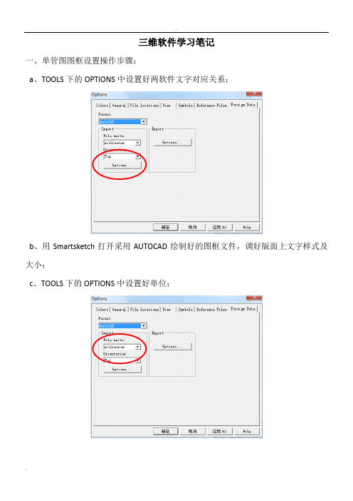
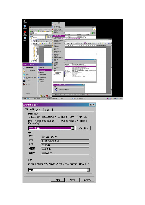
三维软件学习笔记一、单管图图框设置操作步骤:a、TOOLS下的OPTIONS中设置好两软件文字对应关系;b、用Smartsketch打开采用AUTOCAD绘制好的图框文件,调好版面上文字样式及大小;c、TOOLS下的OPTIONS中设置好单位;d、在VIEWS下选择BACKGROUD SHEETS,设置好对应大小的SHEET SETTUP,然后将图框复制过去;e、然后切换至WORKING SHEETS,新建对应大小的SHEET SETTUP此步Name下必须修改为SHEET1f、在SHEET下保存文件为.SHA文件。
g、在下面路径中找到\Program Files(x86)\Smart3D\CatalogData\Bulkload\Datafiles找到bulkloadisokeys.xls文件,打开复制一列,将名称全部对应修改为要添加的图框名称。
采用BULKLOAD下。
h、将a-f步骤创建的图框拷在项目共享文件\\win-v6n6pvm43e2\SharedContent\PmfgIsoStyleData下,然后拷一个相应大小的XML 文件,(COOKTOP2.5打开)将该XML文件中的图框名字对应修改为新建图框的名字,然后保存。
I、ISOGEN设置时,文字报错,修改文字设置如下。
j、在DRAWING AND REPORTS模式下新建ISO文件夹,然后在ISO文件夹下新建如下图的内容,选择下面的pipelinek、存储风格包,如下图,选择SAVE Package。
l、选中新建的风格包,右键选SETUP,新建Filter时选择好处图范围,如下图。
m、然后选中风格包,右键新建图纸,如下图,最后UPDATE NOW即可完成ISO图出图。
备注:平面图图框二、PID中项目备份及恢复操作步骤;a、项目备份:首先打开SMARTPLANT ENGINEERING MANAGER,然后选择具体项目,在TOOLS下选择BACKS,操作步骤如下图。
05_SP3D_Equipment-chinese

Clear stack
© 2005. Intergraph Corporation. All Rights Reserved.
Toggle Display/List only
Set time
设备
SmartSketch 选项设定
© 2005. Intergraph Corporation. All Rights Reserved.
设备
位置关联
• 平行关联
- 只旋转被选择的设备产生约束
Axis
Axis
Before
© 2005. Intergraph Corporation. All Rights Reserved.
After
设备
位置关联
• 与相切面配合关联
- 将设备与一个相切面约束到一个交叉点上,用户在定义切面的矢量方向时就定义 了这个交叉点
设备
设备属性页
• Definition Tab (定义页) • 此页内容是只读的
© 2005. Intergraph Corporation. All Rights Reserved.
设备
设备属性页 • 连接信息页
© 2005. Intergraph Corporation. All Rights Reserved.
Vector defined by two points Mate Surface Tangent Plane
© 2005. Intergraph Corporation. All Rights Reserved.
设备
旋转设备
• 可以使用专门的旋转设备命令
Rotation Axis
• 也可以使用通用旋转命令
设备
旋转设备
S D学习笔记
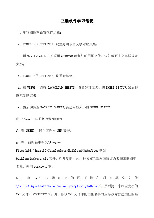
三维软件学习笔记一、单管图图框设置操作步骤:a、TOOLS下的OPTIONS中设置好两软件文字对应关系;b、用Smartsketch打开采用AUTOCAD绘制好的图框文件,调好版面上文字样式及大小;c、TOOLS下的OPTIONS中设置好单位;d、在VIEWS下选择BACKGROUD SHEETS,设置好对应大小的SHEET SETTUP,然后将图框复制过去;e、然后切换至WORKING SHEETS,新建对应大小的SHEET SETTUP此步Name下必须修改为SHEET1f、在 SHEET下保存文件为.SHA文件。
g、在下面路径中找到\ProgramFiles(x86)\Smart3D\CatalogData\Bulkload\Datafiles找到bulkloadisokeys.xls文件,打开复制一列,将名称全部对应修改为要添加的图框名称。
采用BULKLOAD下。
h、将a-f步骤创建的图框拷在项目共享文件\\win-v6n6pvm43e2\SharedContent\PmfgIsoStyleData下,然后拷一个相应大小的XML文件,(COOKTOP2.5打开)将该XML文件中的图框名字对应修改为新建图框的名字,然后保存。
I、ISOGEN设置时,文字报错,修改文字设置如下。
j、在DRAWING AND REPORTS模式下新建ISO文件夹,然后在ISO文件夹下新建如下图的内容,k、存储风格包,如下图,选择SAVE Package。
l、选中新建的风格包,右键选SETUP,新建Filter时选择好处图范围,如下图。
m、然后选中风格包,右键新建图纸,如下图,最后UPDATE NOW即可完成ISO图出图。
备注:平面图图框二、PID中项目备份及恢复操作步骤;a、项目备份:首先打开SMARTPLANT ENGINEERING MANAGER,然后选择具体项目,在TOOLS下选择BACKS,操作步骤如下图。
- 1、下载文档前请自行甄别文档内容的完整性,平台不提供额外的编辑、内容补充、找答案等附加服务。
- 2、"仅部分预览"的文档,不可在线预览部分如存在完整性等问题,可反馈申请退款(可完整预览的文档不适用该条件!)。
- 3、如文档侵犯您的权益,请联系客服反馈,我们会尽快为您处理(人工客服工作时间:9:00-18:30)。
三维软件学习笔记
一、单管图图框设置操作步骤:
a、TOOLS下的OPTIONS中设置好两软件文字对应关系;
b、用Smartsketch打开采用AUTOCAD绘制好的图框文件,调好版面上文字样式及大小;
c、TOOLS下的OPTIONS中设置好单位;
d、在VIEWS下选择BACKGROUD SHEETS,设置好对应大小的SHEET SETTUP,然后将图框复制过去;
e、然后切换至WORKING SHEETS,新建对应大小的SHEET SETTUP
此步Name下必须修改为SHEET1
f、在SHEET下保存文件为.SHA文件。
g、在下面路径中找到
\ProgramFiles(x86)\Smart3D\CatalogData\Bulkload\Datafiles找到bulkloadisokeys.xls文件,打开复制一列,将名称全部对应修改为要添加的图框名称。
采用BULKLOAD下。
h、将a-f步骤创建的图框拷在项目共享文件\\win-v6n6pvm43e2\SharedContent\PmfgIsoStyleData下,然后拷一个相应大小的XML文件,(COOKTOP2.5打开)将该XML文件中的图框名字对应修改为新建图框的名字,然后保存。
I、ISOGEN设置时,文字报错,修改文字设置如下。
j、在DRAWING AND REPORTS模式下新建ISO文件夹,然后在ISO文件夹下新建如下图的内容,
选择下面的pipeline
k、存储风格包,如下图,选择SAVE Package。
l、选中新建的风格包,右键选SETUP,新建Filter时选择好处图范围,如下图。
m、然后选中风格包,右键新建图纸,如下图,最后UPDATE NOW即可完成ISO 图出图。
备注:平面图图框
二、PID中项目备份及恢复操作步骤;
a、项目备份:首先打开SMARTPLANT ENGINEERING MANAGER,然后选择具体项目,在TOOLS下选择BACKS,操作步骤如下图。
b、恢复项目:首先打开SMARTPLANT ENGINEERING MANAGER,然后选择站点,在TOOLS下选择RESTORE,操作步骤如下图。
在INPORT FILE下面找到备份数据ZIP文件夹。
输入备份密码(备份密码为建项目时在数据库中设置的密码)。
在第三步时需更改具体对应的路径。
三、PID中设置绘图规则在intergraphSmartPlant P&ID中选择Options Manager 进行设置。
四、PID中自动断管,可设置画图时自动断管AutoGap,也可画完后在Gap Now。
如下图设置,画图时选择。
五、pid中法兰在Piping下Fitting中的Flanges and Unions里面。
选择要创建的图形,然后在FILE下点击SAVE AS Assembliy,确定保存的路径即可。
六、更改管径显示样式操作步骤如下,
七、SPRD授权操作步骤
八、PID建立ASSEMBLIES时应将所有物件属性及参数填写完整。
PID中复制粘贴管件属性详见下图。
先选择复制源属性管件,然后点此按钮复制
然后选择需要填属性的管件,然后点此按钮粘
贴
九、设备材料报表定制
A、新建报表文件REPORTS,步骤如下图。
B、新建报表,详见下图。
C、编辑模板。
详见下图
D、在TOOLS下点击ADD QUERY,详见下图
E、报表中各属性提取编辑详见下面设备及管件报表截取步骤。
1、管件报表
CATALOG中
2、设备报告
注意事项:创建滤镜时应选对位置。
十、三维软件中自定义LABLE路径如下。
备注:最好新建CUSTOM,放置在该文件下
十一、取消坡度管时应确保角度不被锁死。
十二、SPRD创建等级库
1、元件跟管道连接端在SPRD中要用MATCH,见下图。
十三、报表定制
SQL查询
选择项目的RDB文件,鼠标右键选择NEW QUERY
C:\ProgramFiles (x86)\Smart3D\Core\Tools\Administrator\Bin下找
到MetaDataBrowser
查看接口名字
属性
层级关系
访问接口
1、要将模板存储到CATLOG,必须确保所建过滤器在CATLOG FILTER下。
2、在编辑报表样式时,常量里面可以直接输LABEL,使用方式为[LABEL名]。
序号连续应勾该项
3、
十四、项目备份方法。
点RETORE
十五、出平面图
1、创建视口,如下图,切换视口方向选取出图区域。
相关线处理
图面预处理规则控制图面方向
控制视图边界
创建视口
2、新建NEW COMPOSED
DRAWINGS,
3、
选取第2部创建的
4、
2d3d校对
4、NPD为PIPERUN的属性。
十六、在PIPE FEATURES逻辑断开管子,然后分开进行防腐设置。
十七、坐标方式更换设置
十八、先选择管道,再点击下面按钮选设备,需按住SHIFT。
十九、画好的元件需移动,应在PIPING FEATURES下选择,然后拖动。
二十、平面图风格定制
1、定制管道平面图风格
二十一、如需统计设备表面积设备建模时做法
设备建模时增加
1、然后将SHAPE放置在其下面,然后在SOLID下选择其属性。
2、
二十二、设备管嘴接管尺寸控制设置二十三、SP3D输出到SPR操作步骤
二十四、管道在复制时采用PIPE RUN模式下选择时,选好管道后应在目录树中右键SELECT NESTED。
二十五、设备添加基础
添加后再在STRUCT下去添加基础。
二十六、参照某个物体一定距离画法
二十七、TO DO LIST中错误提示高亮显示在桌面中心操作步骤如下:
1、首先确认选择在ALL状态;
2、在TO DO LIST下面选择某条错误或提示;
3、选择全屏按钮。
二十八、画安全阀操作步骤。
1、
2、选择小端,
3、插入安全阀
4、
5、选择大端连接管道
6、
7、旋转安全阀方向
8、
9、移动安全阀与大端管道对齐,连接大端管道即完成。
二十九、建筑专业房子三维可采用REVIT软件直接导入1、
2、
3、
5、
7、采用SMARTPLANT INTEROP PUBLISHER发布成ifc文件,然后将该文件
拷入该项目网络共享路径下,如下图。
打开Project Management,选中项目鼠标右键,新建New Reference 3D Model。