英特吉NPR48整流模块
ATC48MD系列电源整流模块说明书
五 工作原理及主要特点 ··················································································· 4
5.1 工作原理 ············································································································· 4 5.2 主要特点 ············································································································· 4
由于产品和技术的不断更新、完善,本资料中的内 容可能与实际产品不完全相符,敬请谅解。如需查询产 品的更新情况,请与公司联系。
版次:2008 年 10 月第 1 版,第 1 次印刷
高频开关电源模块使用说明书
目录
目
录
一 概述 ············································································································ 1 二 型号命名 ····································································································· 1 三 正常使用条件 ······························································································ 1 四 主要性能指标 ······························································································ 2
Intergy中功率电源系统

Intergy中功率电源系统——IPS6/7/8000系列,IPS2/3/4/5000系列
特征:
极宽的交流输入电压范围
灵活的模块化设计
预置典型配置软件
强大的用户自定义功能
主动电压控制
完善的电池管理
真正的热插拔
高效率和高功率因数
两级浪涌保护
系统扩容方便快捷更多信息......
IPS6/7/8000 IPS2/3/4/5000 产品手册
英特吉机架式中功率电源系统
IPS6/7/8000系列和IPS2/3/4/5000系列
产品详述
交流输入:( AC input)
标称3φ 220V/380V,50/60Hz
允许电压变化范围150-300V
允许频率变化范围45-66Hz
保护进线过载及短路保护
单独控制每个整流器的配电,提供整流器过载及短路的第二重保护
防雷C级防雷及告警,385V,8/20μS 15-20KA
符合YD5098要求
选项双路市电手动或自动切换输入;交流(单相或三相)进线高低压保护;交流电源电流
(单相或三相)显示
直流输出:(DC Output)
输出分路过载和短路保护任一熔断器或MCB故障自动产生声光告警;
分路缺省负载配电:
4x(25-250A)熔断器+8x(2-63A)MCB 缺省电池配电:
2x(100-600A)熔断器*视负载电流而配
选项电池低压脱离模块:脱离电压及重接电压可按需设置,以保护电池
负载两级脱离模块:脱离电压及重接电压可按需设置,以保护重要负载和电池。
XLR 48V 高功率电源模块说明书
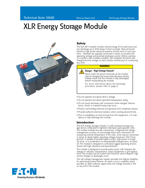
XLR Energy Storage ModuleSafetyThe XLR 48 V module contains stored energy of 54 watt-hours and can discharge up to 9700 amps if short circuited. Only personnel trained in high power electrical systems should work on such sys-tems Modules are typically connected in series to increase the operating voltage and potential discharge current. Before working on a system with modules installed, the module(s) should be dis-charged and the voltage on each module verified prior to conducting any work.IntroductionThe XLR energy storage module is a self-contained energy stor-age device comprised of eighteen individual supercapacitor cells. The module includes bus bar connections, integrated cell voltage management circuitry, an overvoltage alarm and a thermistor formeasuring internal temperature of the cells. Units may be connected in series to obtain higher operating voltage (maximum 750 V from ground), in parallel to provide higher current, high power or longer run time, or a combination of series/parallel arrangements, as need-ed. The module is designed to withstand rugged operating environ-ments with high vibrations and liquid present.The module is designed to provide pulse power with frequent dis-charges in vehicles, transportation, heavy equipment or grid applica-tions. The module can be cooled with forced air when frequent, high current charges or discharges occur.The cell voltage management system provides the highest reliability for optimizing product lifetime. An alarm circuit is available which provides an open collector signal when the voltage exceeds 2.75V on any cell in the module.• D o not operate unit above 48.6 V voltage.• D o not operate unit above specified temperature rating.• D o not touch terminals with conductors while charged. Serious burns, shock, or material fusing may occur.• P rotect surrounding electrical components from incidental contact.• P rovide sufficient electrical isolation when working above 50 Vdc.• P rior to installation on and removal from the equipment, it is man-datory to fully discharge the module.2Technical Note 10509Effective March 2018XLR Energy Storage ModuleEATON InstallationUnpackingInspect the shipping carton for signs of damage prior to unpacking the module. Damage to the shipping carton or module should be reported to the carrier immediately.Remove the module from the shipping carton and retain the ship-ping materials until the unit has been inspected and is determined to be operational.NOTE: The original shipping materials are approved for both air and ground shipment. The module should be removed from the shipping carton by lifting it by the body of the module.Contents:1 Module1 M10 bolt (inserted into negative terminal)1 M8 bolt (Inserted into positive terminal)1. C ommunications mating connector wired (installed on communications connector)If the unit is found to be defective or any parts are missing, contact your local sales representative. A Return Material Authorization(RMA) number must be issued prior to returning the unit for repair or replacement.MechanicalModules are intended for installation horizontally as shown in Figure 5. The module should be mounted on a shelf. The modules should further be secured to the rack using the four mounting holes. See the data sheet for available mounting locations.Theory of OperationSupercapacitors function on electrostatic principles with no chemical reactions and no moving parts. They avoid the lifetime issues associ-ated with chemical storage of batteries or mechanical issues associ-ated with fly wheels. The XLR modules are non-toxic and designed for years of maintenance-free operation.Supercapacitors are intended as energy storage with a DC dis-charge. The module should not be used for AC charging or discharg-ing. Discharges may be constant current or constant power. Example discharges are shown in Figure 1a and 1b. The voltage of the module drops linearly under a constant current discharge.Figure 1a. E xample voltage and current discharge curves for 5 kW discharge fromone module with 48 V float voltage.S y s t e m V o l t a g e (V o l t s )S y s t e m C u r r e n t (A m p s )504030201002502001501005000 5 10 15 20Time (seconds)Discharge Current (A)Voltage (V)Figure 1b. E xample voltage and current discharge curves for 250 A discharge fromone module with 48 V float voltage.S y s t e m V o l t a g e (V o l t s )S y s t e m C u r r e n t (A m p s )50403020100350300250200150100500 5 10 15 20Time (seconds)Discharge Current (A)Voltage (V)Due to the very low equivalent series resistance (ESR) of the super-capacitors, minimal heat is generated during operation. However, as supercapacitors can handle very high currents, a significant heat rise can occur if the discharges and re-charging is frequent and above 50 Arms continuous current.Most systems require multiple modules connected in series to reach higher operating voltages. The XLR module can be series connected for operation up to 750 V (with respect to ground) to meet system level requirements and connected in parallel without limit to meet longer discharge times.Due to manufacturing variations in capacitance and leakage current, cells in a module can differ in voltage. This voltage difference affects the capacitance and equivalent series resistance over time and results in a shortening of the life of the system.The shunt balance circuit monitors the voltage of each cell. When the voltage exceeds the preset 2.8 V , the balancing circuit will dis-charge the cell until the voltage is below 2.7 V .Figure 2. F our mounting points for the module. High vibration environmentsshould mount using the top and bottom holes. A spacer may be needed between the top and bottom plate in this installation. In moderate or low vibration environments, only the holes on the bottom plate are required for securing the module.The module has 4 M8 mounting holes, as shown in Figure 3. A spacer may be needed between the top and bottom plate in high vibration environments. In moderate or low vibration environments, only the holes on the top or bottom plate are required for securing the module. Refer to Figure 4 for the location of mounting holes.369.2Negative T erminal M10196170.077Figure 3. D imensional drawing of module, all dimensions in mm.3Technical Note 10509Effective March 2018XLR Energy Storage Module EATON Figure 4. N i ne series connected modules mounted in a 24” rack. Modules can berotated 90 degrees for a narrower, deeper rack.Output T ermina l PostsThe output terminals of the module consist of threaded Aluminum, female posts . They are designed to connect directly to a ring lug or a bus bar. Apply a layer of high conductivity aluminum-aluminum anti-oxidant joint compound between the mating surfaces. The positive terminal is a threaded M8- female thread and the negative terminal is M10 female threaded. The maximum stack height of lugs/bus bars/lock washers of 0.6” / 15 mm. The maximum depth of the threaded terminal is 20 mm. When applying torque to the terminals, it is recommended to use a maximum torque of 20 N-m / 14.8 ft-lbs. Attachment to the output terminals should be made with ring lugs or bus bars of an appropriate size for the application current and the M8/M10 terminal size. The energy storage modules have low ESR. As a result, the resistance of the cable connecting the energy stor-age module to the load can easily exceed the ESR of the module. Connection of modules in series or parallel or combination thereof should utilize the same gauge wire (or equivalent bus bar) as deter-mined for final output connections. When connecting in series, connect the positive output terminal of one module to the negative output terminal of the next module (as shown in Figure 6 and Figure 8). For parallel connections, connect positive terminals together and negative terminals together (as shown in Figure 7 and Figure 8). When making parallel connections, it is recommended to make the connections at the load to ensure that the resistance across all strings is the same. It is not recommended to use the module termi-nals as a parallel connection point. The maximum operating voltage of a series connected system should not exceed 750 V .All cables connected to the module should have a strain relief to avoid damage to the module terminals in high vibration environ-ments. The cables should be secured to avoid free movement and vibrations on the terminals. This includes the monitoring cable.Figure 5. S eries connected modules (top view). In this example, the system couldprovide 20 KW for 15 seconds at 145.8 V maximum voltage.Figure 6. Parallel connected modules (top view). In this example, the system couldprovide 20 KW for 15 seconds at 48.6 V maximum voltage.Figure 7. 3 Series x 2 Parallel connect modules. In this example, the system wouldprovide 20 kW for 33 seconds or 40 kW for 15 seconds at 145.6 Vmaximum voltage. Recommended connection point for the parallel stringsis at the load or a common terminal block, not on a module terminal.Module-to-Module BalancingThe modules are equipped with voltage management circuitry that reduces the voltage on cells which exceed the rated voltage. The voltage management functions over hours to minimize the standby current requirements. Module-to-module balancing is not required as the balancing system works on each individual cell.4Technical Note 10509Effective March 2018XLR Energy Storage ModuleEATON Overvoltage SignalAn electrically isolated open collector logic output is made available for alarm interface. If a supercapacitor cell is charged above 2.75 V , a signal will be triggered at alarm connector J1 present on module. When several modules are connected in series, parallel or series-parallel combination, the alarm logic output signal can be monitored individually or wire-or’d to form a single fault signal.Below table shows pin out indication of the connector, and maxi-mum current allowed. 5.0 Vdc can be the maximum open circuit voltage across connector provided.Overvoltage Signal Operation1. Overvoltage Pin 2 goes active (closes the circuit to ground) if any cell inside module exceeds overvoltage limit of2.75 V2. Since Pin 2 (overvoltage signal) is an open collector transistor output, pull-up resistor (~1K) connected to a 5 V supply should be connected to Pin 2, as shown in Figure 9.3. When a simple pull up circuit is built around Pin 2, Pin 2 will remain ~5 V when there is no overvoltage which indicates normal operating condition. When the cell goes into over-voltage condition, Pin 2 goes low. This alarming signal can be used to signal system electronics to abort charging of module and to permit overcharged cells to appropriately discharge down to set limits, through a built-in active balancer4. The internal overvoltage circuit can sink up to 5 mA with an output signal low voltage of no more than 0.7 V . When there is no over volt-age signal, maximum leakage current through pull up resistor is 100 nA. Based on the overall electronic system, proper value of the pull-up resistor should be selected.Temperature MonitoringA thermistor is attached to a cell inside the module. This allowsmonitoring of the internal module temperature. The resistance vs. temperature table is provided below. The temperature can be moni-tored with a high impedance, constant current circuit and measuring the voltage.Figure 8. M onitor connector (Deutsch DTM06-4S). Outside the dotted line is arecommended implementation from the system.1423Diode or LEDPull-up resistor Voltage Sourcewhere:I = current RMS AC or DC (amps)Resr = resistance Rac for AC current or Rdc for DC current (ohms) Rth = thermal resistance (o C/W) df = duty cycle fractionThis ∆T plus ambient should remain below the specified maximum operating temperature for the module (please refer to the module datasheet).OperationGeneralThe module should only be operated within specified voltage and temperature ratings. Determine whether current limiting is neces-sary on input/output based on current ratings of ancillary devices. Observe polarity indicated on module. Reverse polarity operation of the module(s) is not recommended and will shorten the lifetime of the product.Electric isolation of the module is tested to 2500 V for maximum operating voltage of 750 Vdc.When several modules are connected in series for operating at higher voltage, care must be taken to ensure proper creepage and clearance distances in compliance with national safety standards for electrical equipment. Monitoring connectorA 4-pin connector (Deutsch DTM06-4S, mating connector DTM04-4P) is provided to monitor overvoltage conditions of cells and cell temperature. These provide warning indicators that a problem may exist in the module or can be monitored for extreme conditions. The connector should not be left to freely move. This will cause vibrations to damage the connector or wires to the connector. Secure the connector to the module, rack or cabi-net. The pin definition is as follows:Thermal PerformanceLow internal resistance of the energy storage modules enables low heat generation within the modules during use. As with any elec-tronic component, the cooler the part operates the longer the ser-vice life. In most applications natural air convection should provide adequate cooling. In severe applications requiring maximum service life, forced airflow may be required.The thermal resistance, Rth, of the units has been experimentally determined assuming free convection at ambient (~ 25 ˚C). The Rth value provided on the data sheet is useful for determining the oper-ating limits for the units. Using the Rth value a module temperature rise can be determined based upon any current and duty cycle. The temperature rise can be expressed by the following equation.Pin #Signal nameOutputMaximum currentColor1GND 2Overvoltage High-not active Low-active5mA White3Not used 4TemperatureSee table BlackT able 1. M onitoring connector pinoutXLR Energy Storage Module Technical Note 10509Effective March 2018T(°C) T(°F) Resistance(kW) -40 -40 348.4-39 -38.2 325.5-38 -36.4 304.3-37 -34.6 284.7-36 -32.8 266.4-35 -31 249.4-34 -29.2 233.7-33 -27.4 219-32 -25.6 205.4-31 -23.8 192.7-30 -22 180.8-29 -20.2 169.8-28 -18.4 159.5-27 -16.6 149.9-26 -14.8 141-25 -13 132.6-24 -11.2 124.8-23 -9.4 117.5-22 -7.6 110.7-21 -5.8 104.3-20 -4 98.33-19 -2.2 92.74-18 -0.4 87.5-17 1.4 82.59-16 3.2 77.98-15 5 73.66-14 6.8 69.61-13 8.6 65.81-12 10.4 62.24-11 12.2 58.88-10 14 55.73-9 15.8 52.76-8 17.6 49.97-7 19.4 47.35-6 21.2 44.88-5 23 42.55-4 24.8 40.36-3 26.6 38.29-2 28.4 36.35-1 30.2 34.51 T(°C) T(°F) Resistance(kW)0 32 32.781 33.8 31.142 35.6 29.63 37.4 28.144 39.2 26.765 41 25.466 42.8 24.237 44.6 23.078 46.4 21.969 48.2 20.9210 50 19.9411 51.8 1912 53.6 18.1213 55.4 17.2814 57.2 16.4815 59 15.7316 60.8 15.0117 62.6 14.3318 64.4 13.6919 66.2 13.0820 68 12.521 69.8 11.9522 71.6 11.4223 73.4 10.9224 75.2 10.4525 77 1026 78.8 9.57227 80.6 9.16428 82.4 8.77629 84.2 8.40630 86 8.05431 87.8 7.71932 89.6 7.433 91.4 7.09534 93.2 6.80535 95 6.52836 96.8 6.26537 98.6 6.01338 100.4 5.77239 102.2 5.54340 104 5.324T(°C) T(°F) Resistance(kW)41 105.8 5.11442 107.6 4.91543 109.4 4.72444 111.2 4.54145 113 4.36746 114.8 4.247 116.6 4.0448 118.4 3.88749 120.2 3.74150 122 3.60151 123.8 3.46852 125.6 3.33953 127.4 3.21754 129.2 3.09955 131 2.98656 132.8 2.87857 134.6 2.77558 136.4 2.67559 138.2 2.5860 140 2.48961 141.8 2.40162 143.6 2.31763 145.4 2.23764 147.2 2.15965 149 2.08566 150.8 2.01367 152.6 1.94568 154.4 1.87969 156.2 1.81570 158 1.75571 159.8 1.69672 161.6 1.6473 163.4 1.58674 165.2 1.53475 167 1.48376 168.8 1.43577 170.6 1.38978 172.4 1.34479 174.2 1.30180 176 1.26T(°C) T(°F) Resistance(kW)81 177.8 1.2282 179.6 1.18183 181.4 1.14484 183.2 1.10985 185 1.07486 186.8 1.04187 188.6 1.00988 190.4 0.978589 192.2 0.948890 194 0.920191 195.8 0.892492 197.6 0.865793 199.4 0.8494 201.2 0.815195 203 0.791196 204.8 0.767997 206.6 0.745598 208.4 0.723999 210.2 0.703100 212 0.6828101 213.8 0.6633102 215.6 0.6444103 217.4 0.6262104 219.2 0.6086105 221 0.5916106 222.8 0.5751107 224.6 0.5591108 226.4 0.5437109 228.2 0.5288110 230 0.5144111 231.8 0.5004112 233.6 0.4868113 235.4 0.4738114 237.2 0.4611115 239 0.4488116 240.8 0.4369117 242.6 0.4254118 244.4 0.4142119 246.2 0.4034120 248 0.3929Temperature monitoringThe temperature sensor is a thermistor with resistance values as shown in the table below.5EATON EatonElectronics Division 1000 Eaton Boulevard Cleveland, OH 44122United States/electronics © 2018 EatonAll Rights Reserved Printed in USAPublication No. 10509March 2018Eaton is a registered trademark.All other trademarks are property of their respective owners.XLR Energy Storage ModuleTechnical Note 10509Effective March 2018Routine MaintenanceClean exterior surface of dirt/grime• Reason - Improve power dissipation performance.• U se a cleaning cloth dampened with a water/soap solution. Do not use high-pressure sprays or immersion • Frequency - AnnuallyCheck mounting fasteners for proper torque • Reason - Avoid mechanical damage • Frequency - AnnuallyInspect housing for signs of damage• Reason - Allows potential internal damage to be identified • Frequency - AnnuallyCheck signal/ground connections• Reason - Avoid false signals or shock hazards • Frequency - AnnuallyStorageThe discharged module can be stored in the original package in a dry place. Discharge a used module prior to stock or shipment. A wire across the terminals should be used to maintain short circuit after having discharged the module.DisposalDo not dispose of module in the trash. Dispose of according to local regulations for general electronics waste.SpecificationsRefer to datasheets at /elx for specifications.MaintenancePrior to removal from the system, cable removal, or any other handling ensure that the energy storage module is completely discharged in a safe manner. The stored energy and the voltage levels may be lethal if mishandling occurs. Maintenance should only be conducted by trained personnel on discharged modules (Paragraph 8.1).Discharge ProcedureProceed as follow to discharge the module:1. Using a voltmeter, measure the voltage between the 2 terminals.2. I f the voltage is above 2 V , a resistor pack (not supplied with the module) will need to be connected between the terminals. Proper care needs to be taken in the design and construction of such a dissipative pack. e.g. At 48 V , for a 2 Ohm pack, the module will be discharged with a peak current of 24 A and will take about 18 minutes to discharge. The heat/power dissipated in the resistor pack will be ~ 1.2 kW. The resistor pack will need to be sized and provided with suitable cooling to handle this power dissipation. Additionally, proper enclosure or other packaging is necessary to ensure safety. In all cases, proper design of the dissipative resis-tor pack is necessary.3. I f the voltage is under 2 V , connect a shorting wire to the + and – connectors.4. T he module is now safe for handling. The shorting wire should be connected at all times until the module is installed in the system and the power cables are connected。
英可瑞通信电源模块用户手册

英可瑞科技高频开关整流模块TR48-3000系列模块用户手册深圳市英可瑞科技开发有限公司目录1概述 (4)2主要特点 (4)3技术指标 (4)4外形结构与接口 (6)4.1外形结构 (6)4.2输入输出接口 (7)5操作说明 (9)6安装与设计 (10)6.1模块散热要求 (10)6.2模块系统插框设计 (10)6.3系统侧接插件装配 (12)7模块外型尺寸 (13)8故障诊断 (14)10包装、运输及储存 (14)10.1包装 (14)10.2运输 (14)10.3储存 (14)1概述TR48-3000系列高频开关整流模块为交流电压输入,直流电压输出可调的ACDC模块。
模块采用DSP数字控制,谐振软开关,有源PFC技术,并且具有多项专利保护;模块具有功率密度高,功率因数高,谐波小,效率高等特点,具备多模块可并联性能。
2主要特点●高效率减少能耗损耗,符合节能减排要求,为客户节省电费。
●高功率密度可节省客户空间,降低系统成本。
●DSP数字控制更少的器件,更高的环境稳定性,更高的可靠性,更便捷的扩容。
●低输入谐波减少对电网的污染,更高的电网适应能力。
●宽输入电压范围,宽输出电压范围适合绝大多数不同输入、输出电压场合。
●宽工作温度范围宽工作温度范围满足大多数严酷的工作环境●热插拔适合方便使用,减少维护费用。
●输入抗高压冲击功能极大提高系统可靠性。
●完善的故障自检测提示丰富的故障检测,方便客户维护。
3技术指标表1模块参数表项目参数指标模块类型TR48-3500(K)TR48-3000(K)TR48-1800(K)TR48-1200(K)TR24-2200(K) 直流输出额定输出功率 3.5kW3kW 1.8kW 1.2kW 2.2kW额定输出电流60A50A30A20A75输出电压范围42VDC~58VDC21~29VDC 限流可调范围10%~110%无级可调峰-峰值杂音≤200mV稳压精度≤±0.5%稳流精度≤±1%均流≤±5%效率100%负载≥92.5%;50%负载≥93%92%/92.5%90.5%/91% 交流输入额定输入电压220VAC//220VDC;110VAC/110VDC(半载)输入电压范围176VAC~300VAC(满载);176VAC~85VAC(降载)176VDC~400VDC(满载);176VDC~85VDC(降载)输入电流<25A<20A<12A<8A<15A 频率45Hz~65Hz功率因素(PF)≥0.99电流失真度(THD)≤5%输入保护保险;防雷电路工作环境条件工作环境温度-40℃~45℃正常工作;45℃~75℃降额输出;存储温度-40℃~75℃相对湿度0~95%海拔2000m满载输出产品安全及可靠性绝缘强度输入对机壳能承受50Hz有效值2500VAC或等效3535VDC耐压1分钟;输入对输出能承受50Hz有效值3000VAC或等效4242VDC耐压1分钟;MTBF>120000小时外形尺寸及重量外形尺寸125mm×41mm×303mm(宽×高×深)模块净重2Kg通讯和告警通讯接口CAN最大并联数量60个警报和状态通过CAN通讯口上告监控,以及面板三个LED和两位按键/三位数码管(可选)显示。
英特吉小系统(SM20)简介

英特吉配置编辑器 英特吉配置编辑器通常安装在笔记本电脑中,并且由施威
(ICE)
特克的工程师在安装和维护时使用。笔记本电脑可通过
SM20 前面板后的 RS232 口与 IMPS 进行连接。
管理模块 (SM20)
管理模块 SM20 监视着 IMPS 的各种功能,并且控制整流 器和 LVD 的操作。所有独立模块都受监视,即任一影响 系统参数的模块故障,SM20 都会产生告警。SM20 可接 收来自电流、电压、温度等传感器输出的模拟信号。SM20 有 8 个继电器输出触点,也用于外部告警电路。
低压脱离 (LVD)
低压脱离保护是为了防止交流停电时间过长时导致电池过 放电而影响电池寿命。用一组电子开关来控制电池的通和 断,当电池电压低于预先设定的电压时,电子开关断开; 当电压上升到预先设定的电压时,电子开关重新闭合。在 操作过程中 LVD 接收来自监控器 SM20 的控制信号。
整流器
整流器的功能是将交流输入电压转化直流输出电压,然后 给电池和负载供电。整流器的交流输入来自用户的交流输 出,MS500 就是从 ACD 上接入的。 每个整流器的直流 输出均连接到直配模块上。SM20 通过多芯控制线控制每 个整流器。整流器告警及其状态通过前面板的发光二极管 显示。
负载
DCD
负A只C适D用和于
MOVs MS500)
交流输出
路
MOV 告警
背
板
进线故障告警
电池温度 房间温度 7 路数字输入
键盘和 显示
RS 232
8 路外部告警 (数字量输出)
输入 输入 输入
接口 延时
SM20
告警 告警 告警 告警 告警
LV电D池控电制流 负载电流
ETP48600用户手册
用于警示潜在的危险情形,若不避免,可能会导致中度 或轻微的人身伤害。
用于传递设备或环境安全警示信息,若不避免,可能会 导致设备损坏、数据丢失、设备性能降低或其它不可预 知的结果。
“注意”不涉及人身伤害。
文档版本 01
ii
ETP48600-D4A1 用户手册
符号
前言
说明 用于突出重要/关键信息、最佳实践和小窍门等。 “说明”不是安全警示信息,不涉及人身、设备及环境 伤害信息。
修订记录
修改记录累积了每次文档更新的说明。最新版本的文档包含以前所有文档版本的更新 内容。
文档版本 01 (2016-01-08)
第一次正式发布。
文档版本 01
iii
ETP48600-D4A1 用户手册
目录
目录
前 言................................................................................................................................................. ii
表32整流模块指示灯说明指示灯颜色状态说明电源指示灯绿色无交流输入整流模块内部损坏05hz闪烁人工查询状态4hz闪烁整流模块处于应用程序加载状态告警指示灯黄色环境温度过高引发的整流模块限功率预告警环境温度过高或过低保护关机告警交流输入过欠压保护整流模块休眠关机05hz闪烁整流模块与外部通讯中断故障指示灯红色整流模块无故障etp48600d4a1用户手册6系统调测文档版本0110指示灯颜色状态说明输出过压锁死整流模块内部故障引起的无输出34监控单元smu06c外观smu06c外观如图35所示
1 安全注意事项.................................................................................................................................. 1
48 kW大功率高频开关电源的研制-8页精选文档
48 kW大功率高频开关电源的研制Development of 48 kW High Frequency Switching Power Supply PAN Min(China Electric Institute,Guangzhou,510300,China)Abstract:The analysis and design of 48 kW high frequency switching power supply are presented.The present state of switching power supply is explained.The operating principle of full bridge phase_shifted converter and realization of soft switching techniques are analysed.Soft switching can reduce switching loss and increase circuit′s efficiency.Integer designing o f power supply system and selection of main device parameters are also proposed.The experiment results demonstrate the power supply device satisfies design requirements completely.It has been applied in electric plating production line success_fully.Keywords:high frequency switching power supply;full bridge phase_shifted;zero voltage switching;soft switching techniques0 引言现有国内外的大功率电源主要为工频整流式电源,体积大、笨重、能耗高、多特性较差,且会对电网造成较大的电磁干扰。
英特吉开关电源维护操作手册(精简版).(DOC)

英特吉开关电源维护操作手册福建移动通信责任有限公司2006年6月目录第一章英特吉开关电源基本原理一、简介二、英特吉电源系统1.交流配电模块2.直流配电模块3.低压脱离模块(LVD)4.整流器5.监控模块SM50第二章英特吉开关电源基本面板图形一、英特吉开关电源机柜二、英特吉开关电源整流模块1.R2948整流模块2.R2948整流模块前面板3.E2730整流模块前面板三、英特吉开关电源SM50 监控器1.SM50 监控器2.SM50监控器指示灯和接口第三章英特吉开关电源参数设置一、参数设置一(施威特系列)二、参数设置二(INTERGY系列)1.SM50监控器菜单2.调整对比度3.安全级别及密码第四章英特吉开关电源故障排除一、电源故障分析一(施威特系列)二、电源故障分析二(INTERGY系列)三、整流器装卸操作程序(INTERGY系列)第五章英特吉开关电源维护规程细则一、巡检目的二、月度巡检项目三、年度巡检项目第一章英特吉开关电源基本原理一、简介本章主要阐述英特吉电源系统(IPS)的基本原理和性能特点及各模块之间的内在关系,其中包括:英特吉电源系统、配电、低压脱离模块、整流器、监控模块SM50。
二、英特吉电源系统IPS8000/IPS7000系列电源系统是复合式机架电源,按进出线方式分,机架共有两种类型,他们是上进下出线和下进下出线。
对于上进上出线系统而方言,上部为交直流配电单元,下部为整流单元及监控单元,对于下进下出线系统而言,下部为交直流配单元,上部为整流单元及监控单元。
本将简述的模块有:●交流配模块●直流配电模块●低压脱离模块(LVD)●整流器●监控模块(SM50)●配置编辑器(软件模块)。
下图为IPS功能框图,显示不同的功能模块是如何相互联连而构成完整的英特吉电源系统。
IPS功能框图配电配电包括供电到整流器的交流输入配电及从整流器到负载或电池的直流输出配电。
在IPS中,有两个模块控制配电(打开带锁的门或直接在面板上就可以操作):1.交流配电模块交流配电模块给整流器提供交流输入电源。
- 1、下载文档前请自行甄别文档内容的完整性,平台不提供额外的编辑、内容补充、找答案等附加服务。
- 2、"仅部分预览"的文档,不可在线预览部分如存在完整性等问题,可反馈申请退款(可完整预览的文档不适用该条件!)。
- 3、如文档侵犯您的权益,请联系客服反馈,我们会尽快为您处理(人工客服工作时间:9:00-18:30)。
上升斜率:可设顶,缺省 8A/s 保护:限流值:可调范围 30-120%RRC,缺省限流点:100%RRC
典型值≤5mV(150kHz-30MHz)
共4页 第2页
离散杂音:典型值≤1mV(3.4kHz-150kHz) 典型值≤1mV(150kHz-200kHz) 典型值≤1mV(200kHz-500kHz) 典型值≤0.1mV(500kHz-30MHz)
可靠性指标 MTBF(根据 HRD5 计算)大于 256953 小时(29.3 年)
当提供通常的负载电流时,R3048(NPR48)运行在最佳状态,达到大于 92﹪的效率, 运行成本极低。R3048(NPR48)能提供恒流及恒功率的运行模式。 特征
整流器(Hot-Swap)快速在线更换 由监控模块自动设定 智能化微处理器控制 高功率密度 高效和一致性功率因数 宽泛的交流电源条件 宽泛的输出电压范围 恒定功率输出或恒定电流输出模式 可现场维护的空气滤清器 符合国际标准 交流输入 标称:220V/50Hz 相电压范048(NPR48)整流模块
英特吉 R3048(NPR48)整流模块可广泛应用于交换、无线和传输。综合使用了卓越的 开关技术及高可靠性的风冷设计,使得 R3048(NPR48)成为灵活、可靠且高效的整流器。 可在 70℃的环境温度,宽范围的交流输入等恶劣环境中正常运行,并具有抗多重浪涌的能 力。
机械参数 机械参数(高、宽、深):222mm(5U),70mm(14E),326mm 重量:5.3kg 连接器:三合一集成化插件:交流/直流/数据
符合标准 中国信息产业部标准
YD/T 731 通信用高频开关整流器 YD/T 585 通信用配电设备 YD/T 1058 通信用高频开关组合电源 国际标准 安全: EN60950 浪涌保护: EN61000-4-5(6KV/3KA)B 级 传导与辐射干扰:EN55022 B 级 交流谐波:EN61000-3-2 A 级
环境要求: 环境温度:标称:25±5℃ 范围:-25~+40℃(安装过滤网)(满载输出) +40~+70℃(减载输出) 相对湿度:标称:50±10%RH 范围:<95%RH(不结露) 海拔高度:<2000m(大于 2000m,可降容使用) 灰尘:<5mg/m3 振动:以 1.5m/s2 5-100Hz,连续作用于任何方向
100-175V(减载输出) 275V-320V 420V 可承受电压 频率范围:45-66Hz 功率因数:>0.99(20-100%RRC) 效率:≥92%(30-85%RRC) ≥90%(20-100%RRC) 输入端熔断器保护:相线和中线高分断快速熔断器
共4页 第1页
输入过压保护:大于 320V 关机 注:RRC 指 58V 时的额定输出电流。 直流输出 整流器额定输出
过热减载:自动调低电流,后备惯技保护 反极性:输出由熔断器进行保护 过压关机:关机点可调,10ms 延时 电压预置精度:±0.1V 负载效应:≤0.5% 恢复时间:0μS 超调量:<0.5% 源效应:≤±0.03% 温度系数:≤±0.02% 电压调整率:≤±0.5% 开关机过冲幅度:无过冲 启动冲击电流:≤100%的最大输入电流有效值 杂音: 电话衡重杂音电压(300-3400Hz)常态典型值:≤1mV 峰-峰值杂音电压(0-20MHz)常态典型值:≤100mV 宽频杂音电压:典型值≤3mV(3.4kHz-150kHz)
共4页 第3页
交流闪变和脉动:EN61000-3-3 抗静电(ESD): EN61000-4-2 B 级 抗射频干扰(RRF): EN61000-4-3 A 级 电快速瞬变(RRF): EN61000-4-4 B 级
共4页 第4页