意大利OBL计量泵MB 系列中文操作手册
OBL MB系列计量泵使用说明

OBL MB系列计量泵使用说明书Page1:OBL公司的MB系列隔膜式计量泵是容积式往复计量泵。
隔膜的每分钟冲程数由电机驱动的、内腔为溅油润滑式的、蜗轮蜗杆的传动决定。
(看图1)MB机械隔膜式计量泵的吸程(隔膜向后冲程)由弹簧复位。
MB系列计量泵的主要特征体现在一个所谓的机械隔膜上,隔膜的往复式运动由偏心轮直接传递。
机械隔膜运作时,既能像柱塞一样产生一液流空间,又在偏心轮与输送的液体间充当一隔离器的作用。
MB机械隔膜式计量泵有双重优点:—泵头无泄漏—无柱塞密封和相关的磨损问题这是因为隔膜的特殊结构(专利),它承受了输送液体的全部冲击力,就像柱塞泵,保证了泵工作的线性流量。
(图表A)图表A:流量线性曲线图OBL机械隔膜的动作反应出柱塞泵的线性流量。
左边图示表明了流量与调节比例间的线性比例关系。
隔膜的往复运动之所以能使泵产生流量,应归功于泵头的进出口单向阀的作用(图2)在进液阶段,进口单向阀打开(这是由隔膜产生的回复所致)而出口单向阀关闭;液体进入泵头,泵进入排液体阶段,在隔膜的压迫作用下,出口单向阀打开而进口单向阀关闭,液体穿过出口单向阀排出。
Page2:理论流量理论流量与隔膜动作时产生的每冲程流量相符合。
图表中的对角直线的流量增加趋势是由隔膜的冲程数增加决定的。
(图3)实际流量实际流量不可避免地要比理论流量小,这是由于液体流经各阀门时,在阀门的反应过程中会产生一定损失。
二个流量间的比率取决于泵的容量有效率。
此效率又与泵的大小、泵头型式(柱塞式或隔膜式)、输送液体、液体的粘度及工作压力等有关。
(图4)流量调节通过一个机械微调旋钮,以手动实现调节流量。
隔膜的冲程调节是无级和逐步的,而且可以在任何时间实现,不管泵是处于工作状态还是非工作状态。
在表B中,列出了安装在MB系列泵上的各种电机参数。
加上的蜗杆与电机轴一体。
●安装空间要充分,以确保操作与维修的安全,尤其在泵头前方(800m)与调节旋钮前方(700m)要留出足够的安装空间。
Sigma 1计量泵操作手册

5.4 改装继电器
40
6 控制元件
41
7 设置
42
7.1 检查可变数值
42
7.2 转到设置模式
42
7.3 转到工作模式
43
7.4 工作模式的设置 SET 菜单
44
7.5 编程功能的设置 SET 菜单
48
7.6 设置存取码
49
7.7 撤销总冲程数和总升数 清除窗口
50
8 运行
50
8.1 手动操作
Hale Waihona Puke 508.2 远程控制
Im Schuhmachergewann 5-11 69123 Heidelberg Postfach 10 17 60 69007 Heidelberg ·Germany Phone: +49 6221 842-0 Fax: +49 6221 842-419 info@prominent.de http://www.prominent.de
安全设备 下述的安全警示必须粘附在计量泵上
符合 EC 标准声明/证书 用于爆炸危险的场所的计量泵包装中有符合 EC 欧共体 标准的声明 爆炸危 险的场所的计量泵 不采用复印件的符合 EC 欧共体 标准的声明
8
1.3 安装 开机和运行的注意事项 警告 — 计量泵的泵头内可能残留出厂前的试验用水 — 当待计量的化学药品不能接触水时 使用前必须将泵头的水全部清理干净 为此 将泵旋转 180°排空泵头 然后从上面经由吸液端用适合的介质冲洗 — 切勿将信号电缆接到电源上! — 如果计量泵在排液端截止阀关闭的情况下强行工作或者计量过程中出现压 力峰值 系统压力会达到最大容许背压的数倍 从而导致输送管线破裂 — 为避免此类情况发生 建议安装一个溢流阀 将计量泵和系统的工作压力限 制在最大容许工作压力以内 — PVT 型泵头的加药装置 不要在溢流阀上连接金属旁路管线 否则 有可 能引起加药装置的爆裂 — 轴承盖 1 在计量泵工作时必须安装好 否则 计量泵不符合 IP55 轴承 没有被安全地保护起来
计量泵操作说明书1
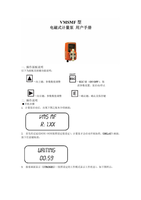
以下为面板及按键功能说明:消参数设置,泵启动/停止二.操作说明1.计量泵启动后,出现下图之版本介绍画面:2. 首先经过延迟时间(时间依照设定值设定),计量泵才会启动开始加药。
《DELAY》画面,按下任意键取消:3. 接着画面显示《STROKES》(依照设定的工作模式显示工作状态),如下图所示:启动/停止计量泵《ESC》键有两个功能,一是取消及放弃参数设置功能;二是作为计量泵的启动/关闭功能。
计量泵于《OFF》状态时,无法进入功能设置页面进行参数设置,如下图所示,按住《ESC》键(约3秒钟)启动计量泵;任何时间或任何设置页面按住《ESC》键(约3秒)可停止计量泵。
(OFF-停止,ON-启动)动作模式设置MODE-PROG[1]VMS MF型计量泵可工作于七种不同模式,分别为:CONSTANT/定量式、DIVIDE/脉冲分配式、MULTIPL Y/脉冲乘算式、PPM/百分比浓度控制式、BATCH/批量式、VOLT/电压控制式、mA/电流控制式。
我们的计量泵都是脉冲输出信号所以只需设置两个参数就可以实现计量泵的加药动作。
MULTIPLY/脉冲乘算式-MOD[03]接收脉冲水表或其他脉冲讯号来源,计量泵以倍数进行加药动作。
倍数最小值为1,错误的数值计量泵将不会储存。
若觉得加药太慢可以适当的增加倍数。
按《向上/向右》键修改参数值,按《E》键储存设置,按《ESC》键放弃修改或离开。
同时设置《DELAY TIME》(讯号周期时间),计量泵将自动把动作间隔平均分散于下一个脉冲讯号之前,请参考初始设置说明《DELAY-SET[05]》。
设置SETUP-PROG[2]除了动作模式设置之外,另外有参数需进行设置,由《MODE-PROG[2]》选单进入。
TIMEOUT/脉冲间隔时间-SET[05]此设置仅对《MULTIPL Y》(脉冲乘算式)动作模式有效。
当计量泵接收到水表的讯号后就开始动作,动作时间为第一个脉冲至下一个脉冲的时间段。
G系列M型隔膜计量泵操作规程
G系列M型隔膜计量泵操作规程概述本文档旨在为使用G系列M型隔膜计量泵的操作人员提供详细的操作规程,以确保安全、高效地使用计量泵。
计量泵介绍G系列M型隔膜计量泵是一种体积可调的计量泵,能够准确地测量和输送液体。
计量泵通过压缩隔膜的方式使液体流动,泵体和动力部件之间通过密封结构隔离,确保泵浆不会通过泵马达进入机体。
由于采用了隔膜传动原理,液体能在正压下输送,也能在负压下抽取。
操作流程1.安装计量泵1.1准备安装环境:根据泵体尺寸和重量,选择合理的安装位置,并清理出足够的空间。
1.2安装支架:在安装位置上建立牢固的支架或基础,使其能够承受泵体和配件的重量。
1.3安装管路系统:将各种管路系统根据需要连接到计量泵上。
L4相关检查:检查计量泵是否与所有管道接口匹配并安装正确。
检查各种管道和阀门是否正确安装并牢固固定,避免泵出现漏气以及其他意外。
2.上下料操作2.1上料操作:先关闭泵的阀门,然后打开液体容器上的进液阀门,将液体缓慢原则注入泵体内,然后把药罐阀门关闭。
2.2下料操作:注意关闭进液阀门,保持出液阀门处于一直打开状态,并使用压缩空气将泵内余液排出。
3.启动和停止3.1启动:关闭出液阀门,将泵接至电源并按下启动按钮,并打开调节气垫压力的阀门。
3.2停止:将所有的进液和出液阀门关闭,然后将泵的电源关闭。
4.故障处理4.1泵出现滴漏:检查密封环发挥卡口是否正确,如果泄漏未解决,则应更换新密封环。
4.2泵没有压力:检查调节气垫压力的阀门是否打开,并检查气垫压力是否调低。
4.3泵发出异常声音:确认泵内无异物卡住,并检查突然变化或漏气部位;如果数据有异常,则应及时上报厂家,并进行相应维修。
注意事项1.操作人员必须经过培训,具备使用计量泵的基本技能,并遵守计量泵的操作规程。
2.必须检查泵体和密封件,并根据工作环境及运行条件进行定期的维护工作。
3.在接触装置或对计量泵进行调整或清洗时,必须关闭所有的闸门,并断开电源。
计量泵的操作规程

计量泵的操作规程第一篇:计量泵的操作规程JYM型隔膜计量泵操作规程1.泵的起动、停止操作1.1.泵起动前的准备工作1.1.1在开车前检查各连接处螺栓是否拧紧,不允许有任何松动,检查管道安装是否正确,进出口管路是否畅通。
1.1.2箱体内加注90#齿轮油,JYM—Ⅰ型油位在离油孔孔底1/3处,JYM—Ⅱ型油位在油尺刻线处,加油30分钟再重新检查油位,并确信出口线路畅通。
1.1.3松开泵头及缸体端排气螺塞,用手转动电机使溶液及油液出现,此过程使空气从泵体内排掉,如果气体封闭在润滑油或泵的液力端,则隔膜泵将不能正常工作.(针对我厂的物料不允许外放的特点,可采取以下方法对泵头进行排气:将阀门切换至打循环状态,用手转动或盘动电机后点动来运行,必要时可调节流量至一定值,来达到排气的目的.) 1. 2泵的运转1.2.1将流量控制旋钮设定在额定的30—40%.1.2.2在最初起动时检查电机正确转向,泵开动10—20秒,停20—30秒,重复几次.在短暂的工作中,听电机或曲轴的声音,不允许有异常的噪声或振动。
1.2.3运转泵半小时到一个小时使油温升高,检查出口流量。
1.2.4流量调至70%,工作10—20分钟。
再降至30—40%运转数分钟,然后再提高到100%运转10分钟,重复几次确保润滑油和液力端的气体被排掉。
1.2.5在泵工作满第一个12小时后,将对泵进行检测和校准,找出在特定工作状态下的确切流量,通常,校准点设在流量的100%、50%、10%之处。
1. 3停泵1.3.1切断电源,停止电机运行。
1.3.2关闭进出口管道阀门,但在泵起动前应注意打开。
1.4泵的行程调节操作1.4.1本泵通过行程调节旋钮按要求顺时针升高流量,逆时针降低流量,调节范围从0—100%。
2.泵的维护、保养2.1传动箱润滑油应保持干净,无杂质及指定的油位量,并适时换油,每年换油两次,每48小时检查一次油位,因本型泵液压缸油与箱体润滑油共用,若油位降低,则会影响液压缸补油,影响泵正常工作。
意大利威尔斯计量泵MB系列说明书
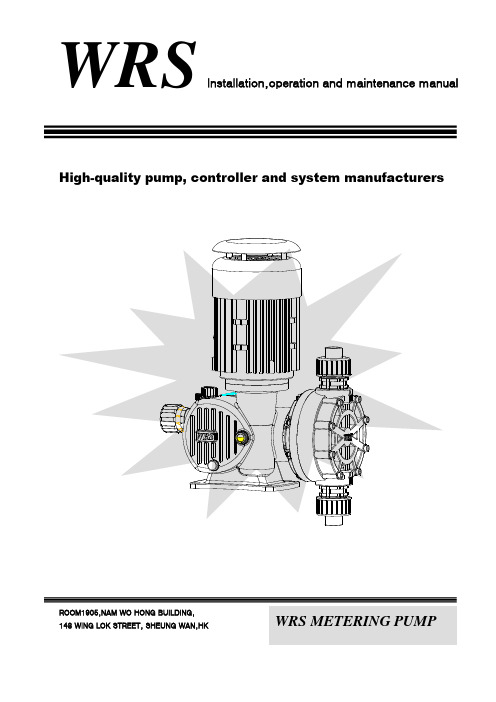
High-quality pump, controller and system manufacturersROOM1905,NAM WO HONG BUILDING, 148 WING LOK STREET, SHEUNG WAN,HKWRS Installation,operation and maintenance manualWRS METERING PUMPWRS services strategyFirst of all check Installation,operation and maintenance manuals in the troubleshooting guide, if the guide does not solve the problem, or is not involved. Please contact your local WRS authorized representative, or contact our Technical Services Department, for further assistance.We will be the professional and technical personnel to solve your fault, and provide solutions. The scope of the warranty of any repairs or alterations need to collect baseline costs and the costs associated with the replacement of parts.1 The equipment installation or maintenance, please read and understand all the instructions and documents.2 In accordance with all special note, remarks and notes.3 In the installation, maintenance and adjustment process, be careful operation and use common sense and good judgement.4 Please ensure that the equipment installation, maintenance and operation process, to comply with your companies and factories all safety and work procedures and standards.5 The start-up before adding oil, or they will burn machines.Equipment checkAccording to orders inspection of all equipment is complete, the existence of the damage. If they were in short supply or damaged, please report immediately to the carrier and your license sales representative.The installation siteIn choosing the location and design with chemical feed systems, should consider providing access to routine maintenance.Can be used for indoor and outdoor running, but running outdoors should use hood or shelter.Pump should be firmly fixed in the flat on the basis of strong, will minimize vibration, or loose connections may cause. Pump fixed with bolts, must be careful not to sloshing base, so as not to affect alignment.The installation of pumps1. Pump should be installed in 300 to 500 mm high above the ground soil mixed suspect, or the corresponding solid-seat, will pump to the level of state correction; more attention to the pump should be installed to pump-and couplings for Correction benchmarks, concentricity error shall not be more than 0.15 mm (flexible coupling), the coupling of steel should be within 0.05 mm;2. S uction tube on the row should not have sharp bend (not more than 90 °), and should minimize the bend in the pipeline and increase the resistance of the parts.3. Will not pump installed in the slot and drug exposure to direct sunlight in it.4. For installation in a barrel on the drug but not greater than 1.5 M, the value of these measures will affect the pump inhalation, equipment maintenance checks due to the need to place more spacious premises.5. Do not easy to install in contravention of the moisture or corrosive gases in it.6. Pump installed in the ambient temperature of -20 ℃~ +40 ℃, at an altitude of 1000 M high following use.Pipeline installation1. inhalation piping path of not less than the inhaled pump valve diameter, and should try to shorten the length of pipeline inhalation, the general 1-2 meters suitable, such as the need to increase the length of time, but not the length of more than four meters (At this point in accordance with equipment Corresponding valve at the end of the filter) (but at the start of inhalation liquid relatively extended time).2. and inhaling, from the valve (flange) connecting the pipeline with valve can not be forced to increase capacity, may not be such as pipes and valves from the weight of Pai suction pump and valve commitment. Pipeline should be installed and supported fixed good pipe.3. special liquid pipeline to the increase in flux3.1 for the transmission and suspension easily precipitate the media, in the pump and from the vicinity of inhalation valves and three links should be created, in order to stop at the pump operator can not open pipe in a tank washing.3.2 In order to ensure the safe operation of pumps and piping system of security, proposed to set up safety valve from the pipeline, such as the need to reduce the transmission of liquid pulse, near the pump discharge pipe installation Shou-road, if the export pumps - Pressure instability, in accordance with the proposed back-pressure valve.With reference to the mapStoreShort-term memory1. In a dry environment, indoor storage at room temperature.2. Should be operating environment requirements, to take precautionary measures to prevent water or moisture into the eccentric device shell.3. Prior to the commencement of a comprehensive examination, then under the instructions to activate the manual pump.Long-term storageIn addition to compliance with the above short-term memory, every 12 months to give motor power to pump at least one hour operation, the implementation of the operation head not in the fluid, but the atmosphere and the import and export must be the same.Pump storage after 12 months, WRS warranty does not include time with the aging of components, such as seals, cushions and divide. If the pump storage over 12 months, recommended in the equipment before the start of the components necessary inspection and replacement. Such replacement of the necessary materials and labour costs should be responsible for the demand side. Please contact the local representative of the WRS pump to obtain the necessary components and services.INTRODUCTIONWRS metering pump is a positive displacement, reciprocating machinery diaphragm pump. Each pump are included, the driving force formed components, power transmission components, import and export components. Medium through Teflon patch of isolation. To ensure that the anti-corrosion products.Principle of operationDiaphragm pumps to the scheduled itinerary for the length of reciprocating movement back and forth, and patch the size, to determine the size of traffic volume through the valve and out of components for the transmission medium.Control ComponentsWRS metering pump is a trip to regulate the length of the device, his itinerary through the length of trip-conditioning components on the scale of the show (0% -100) show. Rotation adjustment hand wheel to adjust the length of the operation after the adjustment of the diaphragm shift length to achieve the effect of traffic control. (Note: The adjustment in pump operation and can operate at the stop, but the pump operation, the operation easier to adjust. Tappet position due to pump spring strength, the pump stopped at the hand wheel adjustment operation of the fixed-conditioning hand wheel nut Will cause damage. Pump in the best-runbest-conditioning).Chart:Hand wheelCalibrationAll measures must be calibrated pump, in accordance with the required flow of accurate set length.On the table for a typical calibration table. Despite the length and set up a linear relationship between output, but exports will be increased pressure to reduce output flow, painted a series of parallel lines, each have a pressure (in the table show only two).Atmospheric pressure to export the output of the divide depends on the flow of displacement, the pump stroke length and frequency of stroke. When output increased pressure on the export flow will decline accordingly. Rated under the pressure of a pump rated flow (see nameplate). Calibration should, as far as possible in the actual operation conducted under conditions (that is, work under pressure in the system using the same or similar process fluid).To create a calibration table, need three or more trips set up under (that is, 25,50,75 and 100) repeatedly measuring flow rate, drawn on the line-drawings of these values, and even between various points to Recently like a straight line. Under the same conditions, this line can be predicted to obtain the necessary flow of the trip settings.Recommended for all users in the system after the installation of the pump flow measurements, to ensure the most accurate and reliable operation.For exampleMaintenanceWarning:Demolition pump in the head position or the maintenance of import and export of valves, please ensure that the system has been relieved, pumping dangerous medium, through the appropriate cleaning and chemistry and to protect the environmental safety. Please Chuanhao protective clothing and use of protective equipment.⒈WRS metering pump divide do not have a fixed life, but the accumulation of impurities and Zasui will cause deformation or divide a one-way valve plug, eventually causing system failure. A pressure system will cause corrosion or chemical failure. Proposed to divide to carry out regular inspection and replacement. Every taste, should be regularly checked, in accordance with their respective systems to determine appropriate conditions for the maintenance interval.Pump accurate records of the early running of the pump will be significant for maintaining the type and extent. Based on this record of maintenance programmes can reduce the incidence of operational failures. Diaphragm and valve components difficult to estimate the life expectancy. By corrosion rate and operating conditions will affect the life of functional materials, each pump must be based on measurement of specific operating conditions to consider.Head componentsDivide the demolition and re-installation⑴. Trip will be set up to regulate 100% and disconnect the power motor.⑵. The release of all the pressure pipeline system.⑶. When invited to take the demolition warnings in the list of all preventive measures.⑷. Import and export of cut-off valve closed.⑸. Pump in the head at a location at the bottom of the pot containing Lou Ye.⑹. The pipeline from the pump head off location, in accordance with the safety of all pumping from the media.⑺. Demolition of all screws, leaving only pump in the head position at the top of a screwdriver. When the screw when the media release from the head position of the pump leaked out.⑻. Tilt the head position will pump check valve in the residual liquid into a suitable container, in compliance with safety instructions.⑼. Demolition of the remaining one screw, use the appropriate medium wash or clean the pump head position and divide.⑽. Counterclockwise rotation removed the divide.⑾. Check whether the divide and enhance the board from cracks or damage. If damage should be replaced.⑿. Installation divide. Clockwise will be installed to divide axis.⒀. Installation of pumps in the head position should be the turn of the screw fastening to ensure that the force uniform.Pump operators 2000-3000 hours after the inspection should be open within the parts, such as the link hub and easy to wear pieces into the repair or replacement. If the long-term disabled at the pump, pump-cylinder medium emissions should be clean, highly corrosive liquid such as, in the stands before the running water for five minutes, rinse the cylinder residual liquid to prevent downtime caused by rot after.Check the demolition and re-installation1 Disconnect the motor power.2 The release of all the pressure in the pipeline system.3 To take the necessary precautionary measures to prevent dangerous substances on the environment and human damage.4 The deadline for closure of import and export of valves.5 And removed the inhalation port connected to the vicinity of the joint pipeline inhalation.6 Gradually loosened and demolish inhalation check valve components, net ranked in the liquid.7 And removed from the vicinity of the port of discharge pipe joints connected8 And slowly release from the demolition check valve components.9 Re-install the new valve components, to ensure that the operation will be placed in the correct port.Note: Each check valves are marked with arrows, specified in the direction of flow of medium (upward). Check the thread without the use of sealants. Retention of each check valve, until the O-ring in close contact with the surface.Valve componentsMotor demolition and re-installation1, disconnect the motor power.2, removed the motor on the wiring.3, the demolition of the four bolts on the motor. Motor shaft was inserted in the worm’s hole.4, Slowly pull out the motor shaft from the worm.5, re-install, in the motor shaft and key-card painted on the lubricating ointment. 6, re-install the motor.7, motor re-wiring.8, connected to motor power.Note:the direction of the motor should be clockwise form the motor itself and keep the same with the arrow at the top of the shell of the pump.(MB Series Parts (1)) (Pump body parts)(MB series of pump parts list):(MB Series Parts (2)) (Component parts control plans)MB series of component parts spare parts inventory control:MB Series Parts (3)(Parts of the pump head site plans)(MB series of pump parts list of sites in the head):The series of pump installation sizeSize baseWRS METERING PUMPROOM1905,NAM WO HONG BUILDING,148 WING LOK STREET, SHEUNG WAN,HKI T A L Y W E I E R S I L I Q U I D C O N T R O L C O.,L I M I T E D。
B系列泵中文说明书

中文说明书Doseuro®S.R.L .ALTERNATIVE DOSING PUMP WITH DIAPHRAGM,INTERPOSED FLUID AND SPRING RETURNSeriesE 125NE 175N E 250NDoseuro 目录1 泵的使用说明2 编码说明3 泵的技术参数4 工况条件5 使用概况6 泵的运输和储存7 去除保护帽8 泵的安装9 泵的位置10 泵与系统的联系11 排液端的连接12 脉动阻尼器的安装13 齿轮油的添加14 电机接线15 噪音16 泵的启动17 泵的调节18 附加设备19 其他附件20 维修保养21 泵头的定期检查22 拆换泵头及膜片23 拆换柱塞24 添加液压油25 工厂维修26 泵的报废27 部件及有害物质的处理1. 泵的使用说明1.1 泵的应用计量泵是应用在需要调节泵的流量的场合。
泵的构成:运动:根据实际的计量情况而调整电机转速, 并通过推杆及复位弹簧将往复运动变为直线运动。
传递运动: 铸铝弹性接头调节:在工作状态下和静止状态下, 都可以通过调节复位弹簧, 在0%-100%之间调整流量。
液力件:通过吸口阀计量并吸入液体,然后通过出口阀排出。
电机:三相或单相电机。
结构: V18-F-CVE三相电源: 220/240V±80/415V 50Hz; 220/280V-380/480V-60Hz单相电源:230V-50Hz我们可以根据客户要求, 提供不同电压和频率的产品。
齿轮箱:铸铝外置零件:推杆的材质是S.S. 420, 保护件及其他附件的材质都是不同种类的塑料。
2 编码说明以下述计量泵为例,说明编码中每个字母代表的意义▲注意泵头材质的技术特点请参阅更多的技术数据表B125N - 25/F 11 DV3 泵的技术参数下面是各系列计量泵技术参数参照表,请仔细阅读,严格按照要求工况运行,确保对泵不造成损坏。
B 125N – E 125N type dataB 175N - E 175N type dataB 250N - E 250N type data4 工况条件泵的实际流量与所输送的液体的粘度,比重及水力损失有关。
计量泵的操作及使用

计量泵操作及使用说明书第一节说明慨述MILROYAL B为往复式容积控制泵,依靠泵入口和出口的正压差输送给定体积的液体,输送量可以准确控制在设定量的1%内。
泵由三个主要部件组成:⑴驱动装置,⑵往复活塞,⑶泵头(液端)。
泵的输出流量是驱动速度、活塞行程长度和活塞直径的函数。
而且,一个给定的输出量是可以通过对泵的行程长度(冲程)进行机械(微米手柄)或(备选)电动或气动调节进行改变,泵驱动可配置填料柱塞(容积阀),圆隔膜或高性能隔膜(双隔膜)泵头。
本手册包含了机械调节驱动部分。
操作原理驱动装置带动泵柱塞,吸入行程时将液体吸入泵头(液端),而在随后的排出行程时将液体排出,只有当排出压力大于吸入压力时,才能获得精确的流量控制。
MILROYAL B型泵独特的驱动机构是专利设计的曲柄原理,涡轮驱动曲柄使之在一个可变的平面上旋转,由于曲柄平面在垂直方向改变,因此通过曲柄与柱塞相连可获得往复运动。
通过从垂直位置开始调节曲柄平面斜度可使泵的行程长度从零增至最大值。
随着柱塞在泵头往复运行,液体便交替的被吸入和排出,在泵的吸入行程(向后),柱塞在泵头腔产生一负压,吸入线上液体压力使吸入口止回阀球体离位,液体流入泵头腔,在排出行程中,柱塞向前移动,在液体上加压,使排出口止回阀球体离位而将液体排出。
在每个吸入行程,排出止回阀球就位,而在每个排出行程,吸入止回阀球就位(泵头压力大于吸入压力)。
这种操作方式的作用是阻止液体回流,并确保液体从吸入端通过泵头腔至排出端排出。
填料柱塞泵头,柱塞与输送液体相接触,而隔膜泵头则使输送液体与柱塞隔离。
在后者的设计中,柱塞移动液体,推动与输送液体相接触的隔膜,迫使输送液体通过泵头。
(隔膜泵头单独进行讲述。
)安全预防措施在安装、操作、维护MILROYAL B型泵时,应事先考虑各安全注意事项。
操作设备时,应使用适宜的工具、防护服和保护镜,安装设备时应注意确保操作安全。
遵守手册的说明,对不同的输送液体应采取适当的安全措施,对危险介质应小心(如腐蚀、有毒、溶剂、酸、碱、可燃物等)。
- 1、下载文档前请自行甄别文档内容的完整性,平台不提供额外的编辑、内容补充、找答案等附加服务。
- 2、"仅部分预览"的文档,不可在线预览部分如存在完整性等问题,可反馈申请退款(可完整预览的文档不适用该条件!)。
- 3、如文档侵犯您的权益,请联系客服反馈,我们会尽快为您处理(人工客服工作时间:9:00-18:30)。
孔目
40 40 30 30
小孔径的过滤器将会影响到计量泵的输出效能;Y 型过滤器尺寸可选用比管路 稍大的型号,且药液粘稠度不可超过 200CPS。
下表中说明 ANSI316L 及 PP.11 型泵头适用的药液粘稠度对照表(不安装过滤 器):
TEL:13811436684
第2页,共11页
TEL:13811436684
1. 技术规格
技术参数
型号
MB11 MB16 MB23 MB31 MB37 MB50 MB35 MB49 MB75 MB101 MB120 MB155
冲程次数 (次/分)
36 50 70 95 115 155 36 50 70 95 115 155
1 – Y 型过滤器 2 – 计量泵 3 – 释压阀
4 – 排水阀 5 – 吐出端-开关阀 6 – 脉冲缓冲器
7 – 压力计
流量与各接头管径参考表:
流量 0 ~ 15 0 ~ 30 0 ~ 125
0 ~ 155
接头管件 4×6 0
-
0 ~ 420
-
法兰管件
-
-
DN10 DN15 1/2” ANSI DN20 3/4” ANSI DN25 1” ANSI
TEL:13811436684
OBL 机械隔膜计量泵 弹簧复位式 中文手册
-MB-
TEL:13811436684
目录
1. 技术规格
3
2. 安装说明
3
2.1 齿轮润滑的种类
内造成损坏或阻塞。 连接泵的吸入及吐出管线必须有独立良好的支撑,以防止液体吐出端管
线振动所造成的损坏或泄漏。 确认管线的连接处及法兰是否完全锁紧,并在安全无虞下进行排气,否
则将会影响计量泵的精确度及不正常加药。
3.2 启动运转 如果计量泵无法正常启动运转,请先由齿轮油箱窗口检查是否有齿
轮油。 检查输入电源及马达旋转方向。 确认吸入端及吐出端管线上所有的开关阀已经开启。 确认管线裹的药液没有凝固或结晶。 计量泵首次启动使用时,尽可能降低吐出端的压力,并且把冲程调整钮
电机 三相电机 单相电机
电源
Δ -230V Y- 400V 110V~115V 220V~240V
频率 50Hz 50Hz
功率 0.2KW 0.24KW
2. 安装说明
2.1 齿轮润滑的种类
※ 注意:安全考量情况下,计量泵出货时内部都没有填充齿轮油,启动运转之前 必须加入齿轮油后才能通电运转,选购齿轮油时请参考下表内相符等级的齿轮
TEL:13811436684
第10页,共11页
TEL: 13811436684
5.3 泵过热 检查是否不正确的接线。 检查是否因为管路背压大于泵的最大输出压力。 检查法兰接头处是否不当安装(拆开检查)。 检查吐出端管路或阀门是否关闭。 检查背压阀压力是否设置过高。 检查计量泵内的润滑油太少
药液飞溅造成人员伤害。 再以清水从泵头的药液吐出端进行清洗,泵仍然维持平躺状态。 依照上述步骤重复清洁约 5 分钟。
5. 故障排除
5.1 没有药液流出
首先先确定泵仍然正常运转: 检查是否有空气流入吸入管路内。 检查泵内是否残留空气。 检查吸入管路太高或太长。 检查药液粘稠度是否太高。 检查吸入端的开关阀是否关闭或管路回路形成短路。 检查吸入端的过滤器是否阻塞。 检查泵上的各个阀件是否阻塞。
排气孔
2.2 安装 安装时吸入端管线长度尽可能缩短,高度不要超过 1.5 米,且管线总长度不要
超过 2.5 米(水平长度加上高度),参考下图的系统安装图。
TEL:13811436684
第4页,共11页
TEL: 13811436684
设定在 20%运转 3 至 5 分钟后,慢慢调整到最大流量后,再把计量泵 设 定在正常的工作压力及流量状态。 计量泵运转一段时间后,检查压力表上显示的压力值,此压力值不应大 于计量泵的最大吐出压力值。
3.3 压力流量曲线图
TEL:13811436684
第9页,共11页
TEL:13811436684
4.2 清洁
泵清洁时请依照下列步骤进行: 将电机上的电源接线盒上盖盖好,将 PG 接头接好,如没有 PG 接头,
则将连接孔以防水胶带密封好。 将泵平躺使吸入阀及吐出阀与地面平行,放置于容易清洁的地方。 使用清水从泵头的药液吸入端进行清洗,冲洗时人员不可太接近,以免
PP11 PP32
A
PP 特氟龙/PTFE PP 特氟龙/PTFE AISI 特氟龙/PTFE 316L
PP AISI 316L
AISI 316L VITON/FPM
PP
INCOLOY 825
HASTELLOY C-276
VITON/FPM
PP AISI 316L
AISI 316L VITON/FPM
流量 (升/时)
11 16 23 31 37 50 35 49 75 101 120 155
最大背压 冲程长度 (bar) (mm)
12 2
8
6
4
接口尺寸
螺纹
法兰
3/8”g.f BSPF
DN15
材料内容 材料 泵头
隔膜
阀件
阀座
阀
密封圈
PP PP 特氟龙/PTFE PP
PVC
PYREX 玻璃 VITON/FPM
2.3 安装范例
带螺纹管件 - 1/4” 3/8” 1/2”
3/4”
1”
PVC 管件 - - Φ Φ16
20 Φ
25 Φ
32
正确安装
错误安装
TEL: 13811436684
第5页,共11页
TEL: 13811436684
更换。 运转模式 连续式
(24 小时运转) 批次式
(间断/交替云转)
工作压力对照 100% 50% 100% 50%
更换时数(月数) 1600 小时(2 个月) 3000 小时(4 个月) 4000 小时(5 个月) 7000 小时(10 个月)
TEL:13811436684
TEL:13811436684
第3页,共11页
TEL:13811436684
润滑油。
每操作 10000 小时请更换齿轮油,如 24 小时操作约为一年更换一次。
厂牌 ESSO(埃索) MOBIL(美孚) SHELL(殼牌)
型号 SPARTAN EP 320 MOBILGEAR 632 OMALA OIL 320
齿轮油添加量 250ml
加油口
齿轮油箱检查窗口
泄油口 ※ 注意:添加完齿轮油之后,请更换具排气孔的油孔盖,参考下图,泵运转过程
时产生的气体从排气孔排出。如齿轮油已经添加后还需要长途的运送,请将油 孔盖更换为没有排气孔的盖子。
第7页,共11页
TEL:13811436684
冲程次数(下/分)
36 50 70 95 115 155
药液粘稠度(CPS)
1000 800 300 150 50 10
3. 操作说明
3.1 运转前检查
计量泵运转操作前请依照下列事项检查: 确认计量泵安装平稳牢固,请勿将计量泵直接安装在水泥基座上。 使用计量泵底部的螺丝孔安装、固定。 确认计量泵泵头上下端的阀与地面呈垂直状态。 管线与计量泵连接之前,请确实清洁管线及药桶内部,以免杂质吸入泵
TEL: 13811436684
第11页,共11页
过滤底阀
管线过大
管线太细
TEL: 13811436684
第6页,共11页
TEL:13811436684
含过滤器安装方式(过滤器尺寸请参考下表)
过滤器选型参照表:
流量 0 ~ 15 15 ~ 50 100 ~ 200 200 ~ 420
第8页,共11页
TEL:13811436684
计量泵的输出流量受到加药点背压的影响,背压越大流量越少。
3.4 冲程调整
计量泵运转的过程中或是停止时,随时可以调整冲程长度,改变加药量。如下 图
4. 保养及清洁
4.1 定期更换 为了避免膜片破损所造成的损坏或影响,依参考下表进行定期保养或
5.2 加药量过少 首先先确定泵仍然
正常运转: 检查是否有空气流入吸入管路内。 检查泵内是否残留空气。 检查吸入端的管件是否过大。 检查药液粘稠度是否太高。 检查药桶是否完全密封无法排气。 检查吸入端的开关阀是否关闭或管路回路形成短路。 检查吸入端的过滤器是否阻塞。 检查泵上的各个阀件是否阻塞。 检查安全释压阀压力是否设置过低。
3
2.2 安装
4
2.3 安装范例
5
3. 操作说明
8
3.1 运转前检查
8
3.2 启动运转
8
3.3 压力流量曲线图
8
3.4 冲程调整
9
4. 保养及清洁
9
4.1 定期更换
9
4.2 清洁
10
5. 故障排除
10
5.1 没有药液流出
10
5.2 加药量过少
10
5.3 泵过热
11
TEL:13811436684