机电专业论文英文文献及其中文译文
直流电动机中英文对照外文翻译文献

中英文对照外文翻译文献(文档含英文原文和中文翻译)外文文献:DC Motor CalculationsOverviewNow that we have a good understanding of dc generators, we can begin our study of dc motors. Direct-current motors transform electrical energy into mechanical energy. They drive devices such as hoists, fans, pumps, calendars, punch-presses, and cars. These devices may have a definite torque-speed characteristic (such as a pump or fan) or a highly variable one (such as a hoist or automobile). The torque-speed characteristic of the motor must be adapted to the type of the load it has to drive, and this requirement has given rise to three basic types of motors: 1.Shunt motors 2. Series motors 3. Compound motors Direct-current motors are seldom used in ordinary industrial applications because all electric utility systems furnish alternating current. However, for special applications such as in steel mills, mines, and electric trains, it is sometimes advantageous to transform the alternating current into direct current in order to use dc motors. The reason is that the torque-speed characteristics of dc motors can be varied over a wide range while retaining high efficiency. Today, this general statement can be challenged because the availability of sophisticated electronic drives has made it possible to use alternating current motors for variable speed applications. Nevertheless, there are millions of dc motors still in service and thousands more are being produced every year.Counter-electromotive force (cemf)Direct-current motors are built the same way as generators are; consequently, a dc machine can operate either as a motor or as a generator. To illustrate, consider a dc generator in which the armature, initially at rest, is connected to a dc source E s by means of a switch (Fig. 5.1). The armature has a resistance R, and the magnetic field is created by a set of permanent magnets.As soon as the switch is closed, a large current flows in the armature because its resistance is very low. The individual armature conductors are immediately subjected to a force because they are immersed in the magnetic field created by the permanent magnets. These forces add upto produce a powerful torque, causing the armature to rotate.Figure 5.1 Starting a dc motor across the line.On the other hand, as soon as the armature begins to turn, a second phenomenon takes place: the generator effect. We know that a voltage E o is induced in the armature conductors as soon as they cut a magnetic field (Fig. 5.2). This is always true, no matter what causes the rotation. The value and polarity of the induced voltage are the same as those obtained when the machine operates as a generator. The induced voltage E o is therefore proportional to the speed of rotation n of the motor and to the flux F per pole, as previously given by Eq. 5.1:E o = Zn F/60 (5.1)As in the case of a generator, Z is a constant that depends upon the number of turns on the armature and the type of winding. For lap windings Z is equal to the number of armature conductors.In the case of a motor, the induced voltage E o is called counter-electromotive force (cemf) because its polarity always acts against the source voltage E s. It acts against the voltage in the sense that the net voltage acting in the series circuit of Fig. 5.2 is equal to (E s - Eo) volts and not (E s + E o) volts.Figure 5.2 Counter-electromotive force (cemf) in a dc motor.Acceleration of the motorThe net voltage acting in the armature circuit in Fig. 5.2 is (E s- E o) volts. The resulting armature current /is limited only by the armature resistance R, and soI = (E s- E o)IR (5.2)When the motor is at rest, the induced voltage E o= 0, and so the starting current isI = E s/RThe starting current may be 20 to 30 times greater than the nominal full-load current of the motor. In practice, this would cause the fuses to blow or the circuit-breakers to trip. However, if they are absent, the large forces acting on the armature conductors produce a powerful starting torque and a consequent rapid acceleration of the armature.As the speed increases, the counter-emf E o increases, with the result that the value of (E s—E o)diminishes. It follows from Eq. 5.1 that the armature current / drops progressively as the speed increases.Although the armature current decreases, the motor continues to accelerate until it reaches a definite, maximum speed. At no-load this speed produces a counter-emf E o slightly less than the source voltage E s. In effect, if E o were equal to E s the net voltage (E s—E o) would become zero and so, too, would the current /. The driving forces would cease to act on the armature conductors, and the mechanical drag imposed by the fan and the bearings would immediately cause the motor to slow down. As the speed decreases the net voltage (E s—E o) increases and so does the current /. The speed will cease to fall as soon as the torque developed by the armature current is equal to the load torque. Thus, when a motor runs at no-load, the counter-emf must be slightly less than E s so as to enable a small current to flow, sufficient to produce the required torque.Mechanical power and torqueThe power and torque of a dc motor are two of its most important properties. We now derive two simple equations that enable us to calculate them.1. According to Eq. 5.1 the cemf induced in a lap-wound armature is given byE o = Zn F/60Referring to Fig. 5.2, the electrical power P a supplied to the armature is equal to the supply voltage E s multiplied by the armature current I:P a = E s I (5.3)However, E s is equal to the sum of E o plus the IR drop in the armature:E s = E o + IR (5.4)It follows thatP a= E s I= (E o + IR)I=E o I + I2R (5.5)The I2R term represents heat dissipated in the armature, but the very important term E o I is the electrical power that is converted into mechanical power. The mechanical power of the motor is therefore exactly equal to the product of the cemf multiplied by the armature currentP = E o I (5.6)whereP = mechanical power developed by the motor [W]E o= induced voltage in the armature (cemf) [V]I = total current supplied to the armature [A]2. Turning our attention to torque T, we know that the mechanical power P is given by the expressionP = nT/9.55 (5.7)where n is the speed of rotation.Combining Eqs. 5.7,5.1, and 5.6, we obtainnT/9.55 = E o I= ZnFI/60and soT =Z F I/6.28The torque developed by a lap-wound motor is therefore given by the expressionT =Z F I/6.28 (5.8)whereT = torque [N×m]Z = number of conductors on the armatureF = effective flux per pole [Wb]*/ = armature current [A]6.28 = constant, to take care of units[exact value = 2p]Eq. 5.8shows that we can raise the torque of a motor either by raising the armature current or by raising the flux created by the poles.Speed of rotationWhen a dc motor drives a load between no-load and full-load, the IR drop due to armature resistance is always small compared to the supply voltage E s. This means that the counter-emf E s is very nearly equal to E s.On the other hand, we have already seen that Eo may be expressed by the equationE o = Zn F/60Replacing E o by E s we obtainE s = Zn F/60That is,wheren = speed of rotation [r/min]E s = armature voltage [V]Z = total number of armature conductorsThis important equation shows that the speed of the motor is directly proportional to the armature supply voltage and inversely proportional to the flux per pole. We will now study how this equation is applied.Armature speed controlAccording to Eq. 5.8, if the flux per pole F is kept constant (permanent magnet field or field with fixed excitation), the speed depends only upon the armature voltage E s. By raising or lowering E s the motor speed will rise and fall in proportion.In practice, we can vary E s by connecting the motor armature M to a separately excited variable-voltage dc generator G . The field excitation of the motor is kept constant, but the generator excitation I x can be varied from zero to maximum and even reversed. The generator output voltage E s can therefore be varied from zero to maximum, with either positive or negative polarity. Consequently, the motor speed can be varied from zero to maximum in either direction. Note that the generator is driven by an ac motor connected to a 3-phase line. This method of speed control, known as the Ward-Leonard system, is found in steel mills, high-rise elevators, mines, and paper mills.In modem installations the generator is often replaced by a high-power electronic converter that changes the ac power of the electrical utility to dc, by electronic means.What happens to the dc power received by generator G? When G receives electric power, it operates as a motor, driving its own ac motor as an asynchronous generator!* As a result, ac power is fed back into the line that normally feeds the ac motor. The fact that power can be recovered this way makes the Ward-Leonard system very efficient, and constitutes another of its advantages.Rheostat Speed ControlAnother way to control the speed of a dc motor is to place a rheostat in series with the armature . The current in the rheostat produces a voltage drop which subtracts from the fixed source voltage E s, yielding a smaller supply voltage across the armature. This method enables us to reduce the speed below its nominal speed. It is only recommended for small motors because a lot of power and heat is wasted in the rheostat, and the overall efficiency is low. Furthermore, thespeed regulation is poor, even for a fixed setting of the rheostat. In effect, the IR drop across the rheostat increases as the armature current increases. This produces a substantial drop in speed with increasing mechanical load.中文译文:直流电动机的计算概述现在,我们对直流发电机有一个很好的了解,我们可以开始对直流电动机的研究了。
(完整版)电机学英文文献翻译

Widespread use in production machines without changing the synchronous speed of motor speed control method Wound Rotor Series Resistance Speed, chopper speed control, cascade control, and application of electromagnetic slip clutch, fluid couplings, clutches and other film speed. Change the synchronous speed of change on the number of stator pole multi-speed motor to change the stator voltage and frequency to frequency conversion with no change to the motor speed and so on.
Energy from the speed point of view when, with high speed method and inefficient methods of two kinds of speed: high speed when the slip refers to the same, so no slip losses, such as multi-speed motors, Slip frequency control and loss can speed recovery methods (such as cascade control, etc.). A deteriorating loss of speed control methods are inefficient speed, such as series resistance of the rotor speed method, the energy loss in the rotor circuit on; Electromagnetic Clutch The speed method, the energy loss in the clutch coils; fluid coupling speed, energy loss in the fluid coupling of the oil. General deterioration in loss increased with the expansion speed range, if not speed range, the energy loss is minimal.
机械加工毕业论文中英文资料外文翻译文献
毕业论文中英文资料外文翻译文献附录附录1:英文原文Selection of optimum tool geometry and cutting conditionsusing a surface roughness prediction model for end milling Abstract Influence of tool geometry on the quality of surface produced is well known and hence any attempt to assess the performance of end milling should include the tool geometry. In the present work, experimental studies have been conducted to see the effect of tool geometry (radial rake angle and nose radius) and cutting conditions (cutting speed and feed rate) on the machining performance during end milling of medium carbon steel. The first and second order mathematical models, in terms of machining parameters, were developed for surface roughness prediction using response surface methodology (RSM) on the basis of experimental results. The model selected for optimization has been validated with the Chi square test. The significance of these parameters on surface roughness has been established with analysis of variance. An attempt has also been made to optimize the surface roughness prediction model using genetic algorithms (GA). The GA program gives minimum values of surface roughness and their respective optimal conditions.1 IntroductionEnd milling is one of the most commonly used metal removal operations in industry because of its ability to remove material faster giving reasonably good surface quality. It is used in a variety of manufacturing industries including aerospace and automotive sectors, where quality is an important factor in the production of slots, pockets, precision moulds and dies. Greater attention is given to dimensional accuracy and surface roughness of products by the industry these days. Moreover, surface finish influences mechanical properties such as fatigue behaviour, wear, corrosion, lubrication and electrical conductivity. Thus, measuring and characterizing surface finish can be considered for predicting machining performance.Surface finish resulting from turning operations has traditionally received considerable research attention, where as that of machining processes using multipoint cutters, requires attention by researchers. As these processes involve large number of parameters, it would bedifficult to correlate surface finish with other parameters just by conducting experiments. Modelling helps to understand this kind of process better. Though some amount of work has been carried out to develop surface finish prediction models in the past, the effect of tool geometry has received little attention. However, the radial rake angle has a major affect on the power consumption apart from tangential and radial forces. It also influences chip curling and modifies chip flow direction. In addition to this, researchers [1] have also observed that the nose radius plays a significant role in affecting the surface finish. Therefore the development of a good model should involve the radial rake angle and nose radius along with other relevant factors.Establishment of efficient machining parameters has been a problem that has confronted manufacturing industries for nearly a century, and is still the subject of many studies. Obtaining optimum machining parameters is of great concern in manufacturing industries, where the economy of machining operation plays a key role in the competitive market. In material removal processes, an improper selection of cutting conditions cause surfaces with high roughness and dimensional errors, and it is even possible that dynamic phenomena due to auto excited vibrations may set in [2]. In view of the significant role that the milling operation plays in today’s manufacturing world, there is a need to optimize the machining parameters for this operation. So, an effort has been made in this paper to see the influence of tool geometry(radial rake angle and nose radius) and cutting conditions(cutting speed and feed rate) on the surface finish produced during end milling of medium carbon steel. The experimental results of this work will be used to relate cutting speed, feed rate, radial rake angle and nose radius with the machining response i.e. surface roughness by modelling. The mathematical models thus developed are further utilized to find the optimum process parameters using genetic algorithms.2 ReviewProcess modelling and optimization are two important issues in manufacturing. The manufacturing processes are characterized by a multiplicity of dynamically interacting process variables. Surface finish has been an important factor of machining in predicting performance of any machining operation. In order to develop and optimize a surface roughness model, it is essential to understand the current status of work in this area.Davis et al. [3] have investigated the cutting performance of five end mills having various helix angles. Cutting tests were performed on aluminium alloy L 65 for three milling processes (face, slot and side), in which cutting force, surface roughness and concavity of a machined plane surface were measured. The central composite design was used to decide on the number of experiments to be conducted. The cutting performance of the end mills was assessed usingvariance analysis. The affects of spindle speed, depth of cut and feed rate on the cutting force and surface roughness were studied. The investigation showed that end mills with left hand helix angles are generally less cost effective than those with right hand helix angles. There is no significant difference between up milling and down milling with regard tothe cutting force, although the difference between them regarding the surface roughness was large. Bayoumi et al.[4] have studied the affect of the tool rotation angle, feed rate and cutting speed on the mechanistic process parameters (pressure, friction parameter) for end milling operation with three commercially available workpiece materials, 11 L 17 free machining steel, 62- 35-3 free machining brass and 2024 aluminium using a single fluted HSS milling cutter. It has been found that pressure and friction act on the chip – tool interface decrease with the increase of feed rate and with the decrease of the flow angle, while the cutting speed has a negligible effect on some of the material dependent parameters. Process parameters are summarized into empirical equations as functions of feed rate and tool rotation angle for each work material. However, researchers have not taken into account the effects of cutting conditions and tool geometry simultaneously; besides these studies have not considered the optimization of the cutting process.As end milling is a process which involves a large number f parameters, combined influence of the significant parameters an only be obtained by modelling. Mansour and Abdallaet al. [5] have developed a surface roughness model for the end milling of EN32M (a semi-free cutting carbon case hardening steel with improved merchantability). The mathematical model has been developed in terms of cutting speed, feed rate and axial depth of cut. The affect of these parameters on the surface roughness has been carried out using response surface methodology (RSM). A first order equation covering the speed range of 30–35 m/min and a second order equation covering the speed range of 24–38 m/min were developed under dry machining conditions. Alauddin et al. [6] developed a surface roughness model using RSM for the end milling of 190 BHN steel. First and second order models were constructed along with contour graphs for the selection of the proper combination of cutting speed and feed to increase the metal removal rate without sacrificing surface quality. Hasmi et al. [7] also used the RSM model for assessing the influence of the workpiece material on the surface roughness of the machined surfaces. The model was developed for milling operation by conducting experiments on steel specimens. The expression shows, the relationship between the surface roughness and the various parameters; namely, the cutting speed, feed and depth of cut. The above models have not considered the affect of tool geometry on surface roughness.Since the turn of the century quite a large number of attempts have been made to find optimum values of machining parameters. Uses of many methods have been reported in the literature to solve optimization problems for machining parameters. Jain and Jain [8] have usedneural networks for modeling and optimizing the machining conditions. The results have been validated by comparing the optimized machining conditions obtained using genetic algorithms. Suresh et al. [9] have developed a surface roughness prediction model for turning mild steel using a response surface methodology to produce the factor affects of the individual process parameters. They have also optimized the turning process using the surface roughness prediction model as the objective function. Considering the above, an attempt has been made in this work to develop a surface roughness model with tool geometry and cutting conditions on the basis of experimental results and then optimize it for the selection of these parameters within the given constraints in the end milling operation.3 MethodologyIn this work, mathematical models have been developed using experimental results with the help of response surface methodolog y. The purpose of developing mathematical models relating the machining responses and their factors is to facilitate the optimization of the machining process. This mathematical model has been used as an objective function and the optimization was carried out with the help of genetic algorithms.3.1 Mathematical formulationResponse surface methodology(RSM) is a combination of mathematical and statistical techniques useful for modelling and analyzing the problems in which several independent variables influence a dependent variable or response. The mathematical models commonly used are represented by:where Y is the machining response, ϕ is the response function and S, f , α, r are milling variables and ∈is the error which is normally distributed about the observed response Y with zero mean.The relationship between surface roughness and other independent variables can be represented as follows,where C is a constant and a, b, c and d are exponents.To facilitate the determination of constants and exponents, this mathematical model will have to be linearized by performing a logarithmic transformation as follows:The constants and exponents C, a, b, c and d can be determined by the method of least squares. The first order linear model, developed from the above functional relationship using least squares method, can be represented as follows:where Y1 is the estimated response based on the first-order equation, Y is the measured surface roughness on a logarithmic scale, x0 = 1 (dummy variable), x1, x2, x3 and x4 are logarithmic transformations of cutting speed, feed rate, radial rake angle and nose radiusrespectively, ∈is the experimental error and b values are the estimates of corresponding parameters.The general second order polynomial response is as given below:where Y2 is the estimated response based on the second order equation. The parameters, i.e. b0, b1, b2, b3, b4, b12, b23, b14, etc. are to be estimated by the method of least squares. Validity of the selected model used for optimizing the process parameters has been tested with the help of statistical tests, such as F-test, chi square test, etc. [10].3.2 Optimization using genetic algorithmsMost of the researchers have used traditional optimization techniques for solving machining problems. The traditional methods of optimization and search do not fare well over a broad spectrum of problem domains. Traditional techniques are not efficient when the practical search space is too large. These algorithms are not robust. They are inclined to obtain a local optimal solution. Numerous constraints and number of passes make the machining optimization problem more complicated. So, it was decided to employ genetic algorithms as an optimization technique. GA come under the class of non-traditional search and optimization techniques. GA are different from traditional optimization techniques in the following ways:1.GA work with a coding of the parameter set, not the parameter themselves.2.GA search from a population of points and not a single point.3.GA use information of fitness function, not derivatives or other auxiliary knowledge.4.GA use probabilistic transition rules not deterministic rules.5.It is very likely that the expected GA solution will be the global solution.Genetic algorithms (GA) form a class of adaptive heuristics based on principles derived from the dynamics of natural population genetics. The searching process simulates the natural evaluation of biological creatures and turns out to be an intelligent exploitation of a random search. The mechanics of a GA is simple, involving copying of binary strings. Simplicity of operation and computational efficiency are the two main attractions of the genetic algorithmic approach. The computations are carried out in three stages to get a result in one generation or iteration. The three stages are reproduction, crossover and mutation.In order to use GA to solve any problem, the variable is typically encoded into a string (binary coding) or chromosome structure which represents a possible solution to the given problem. GA begin with a population of strings (individuals) created at random. The fitness of each individual string is evaluated with respect to the given objective function. Then this initial population is operated on by three main operators – reproduction cross over and mutation– to create, hopefully, a better population. Highly fit individuals or solutions are given theopportunity to reproduce by exchanging pieces of their genetic information, in the crossover procedure, with other highly fit individuals. This produces new “offspring” solutions, which share some characteristics taken from both the parents. Mutation is often applied after crossover by altering some genes (i.e. bits) in the offspring. The offspring can either replace the whole population (generational approach) or replace less fit individuals (steady state approach). This new population is further evaluated and tested for some termination criteria. The reproduction-cross over mutation- evaluation cycle is repeated until the termination criteria are met.4 Experimental detailsFor developing models on the basis of experimental data, careful planning of experimentation is essential. The factors considered for experimentation and analysis were cutting speed, feed rate, radial rake angle and nose radius.4.1 Experimental designThe design of experimentation has a major affect on the number of experiments needed. Therefore it is essential to have a well designed set of experiments. The range of values of each factor was set at three different levels, namely low, medium and high as shown in Table 1. Based on this, a total number of 81 experiments (full factorial design), each having a combination of different levels of factors, as shown in Table 2, were carried out.The variables were coded by taking into account the capacity and limiting cutting conditions of the milling machine. The coded values of variables, to be used in Eqs. 3 and 4, were obtained from the following transforming equations:where x1 is the coded value of cutting speed (S), x2 is the coded value of the feed rate ( f ), x3 is the coded value of radial rake angle(α) and x4 is the coded value of nose radius (r).4.2 ExperimentationA high precision ‘Rambaudi Rammatic 500’ CNC milling machine, with a vertical milling head, was used for experimentation. The control system is a CNC FIDIA-12 compact. The cutting tools, used for the experimentation, were solid coated carbide end mill cutters of different radial rake angles and nose radii (WIDIA: DIA20 X FL38 X OAL 102 MM). The tools are coated with TiAlN coating. The hardness, density and transverse rupture strength are 1570 HV 30, 14.5 gm/cm3 and 3800 N/mm2 respectively.AISI 1045 steel specimens of 100×75 mm and 20 mm thickness were used in the present study. All the specimens were annealed, by holding them at 850 ◦C for one hour and then cooling them in a furnace. The chemical analysis of specimens is presented in Table 3. Thehardness of the workpiece material is 170 BHN. All the experiments were carried out at a constant axial depth of cut of 20 mm and a radial depth of cut of 1 mm. The surface roughness (response) was measured with Talysurf-6 at a 0.8 mm cut-off value. An average of four measurements was used as a response value.5 Results and discussionThe influences of cutting speed, feed rate, radial rake angle and nose radius have been assessed by conducting experiments. The variation of machining response with respect to the variables was shown graphically in Fig. 1. It is seen from these figures that of the four dependent parameters, radial rake angle has definite influence on the roughness of the surface machined using an end mill cutter. It is felt that the prominent influence of radial rake angle on the surface generation could be due to the fact that any change in the radial rake angle changes the sharpness of the cutting edge on the periphery, i.e changes the contact length between the chip and workpiece surface. Also it is evident from the plots that as the radial rake angle changes from 4◦to 16◦, the surface roughness decreases and then increases. Therefore, it may be concluded here that the radial rake angle in the range of 4◦to 10◦would give a better surface finish. Figure 1 also shows that the surface roughness decreases first and then increases with the increase in the nose radius. This shows that there is a scope for finding the optimum value of the radial rake angle and nose radius for obtaining the best possible quality of the surface. It was also found that the surface roughness decreases with an increase in cutting speed and increases as feed rate increases. It could also be observed that the surface roughness was a minimum at the 250 m/min speed, 200 mm/min feed rate, 10◦radial rake angle and 0.8 mm nose radius. In order to understand the process better, the experimental results can be used to develop mathematical models using RSM. In this work, a commercially available mathematical software package (MATLAB) was used for the computation of the regression of constants and exponents.5.1 The roughness modelUsing experimental results, empirical equations have been obtained to estimate surface roughness with the significant parameters considered for the experimentation i.e. cutting speed, feed rate, radial rake angle and nose radius. The first order model obtained from the above functional relationship using the RSM method is as follows:The transformed equation of surface roughness prediction is as follows:Equation 10 is derived from Eq. 9 by substituting the coded values of x1, x2, x3 and x4 in termsof ln s, ln f , lnαand ln r. The analysis of the variance (ANOV A) and the F-ratio test have been performed to justify the accuracy of the fit for the mathematical model. Since the calculated values of the F-ratio are less than the standard values of the F-ratio for surface roughness as shown in Table 4, the model is adequate at 99% confidence level to represent the relationship between the machining response and the considered machining parameters of the end milling process.The multiple regression coefficient of the first order model was found to be 0.5839. This shows that the first order model can explain the variation in surface roughness to the extent of 58.39%. As the first order model has low predictability, the second order model has been developed to see whether it can represent better or not.The second order surface roughness model thus developed is as given below:where Y2 is the estimated response of the surface roughness on a logarithmic scale, x1, x2, x3 and x4 are the logarithmic transformation of speed, feed, radial rake angle and nose radius. The data of analysis of variance for the second order surface roughness model is shown in Table 5.Since F cal is greater than F0.01, there is a definite relationship between the response variable and independent variable at 99% confidence level. The multiple regression coefficient of the second order model was found to be 0.9596. On the basis of the multiple regression coefficient (R2), it can be concluded that the second order model was adequate to represent this process. Hence the second order model was considered as an objective function for optimization using genetic algorithms. This second order model was also validated using the chi square test. The calculated chi square value of the model was 0.1493 and them tabulated value at χ2 0.005 is 52.34, as shown in Table 6, which indicates that 99.5% of the variability in surface roughness was explained by this model.Using the second order model, the surface roughness of the components produced by end milling can be estimated with reasonable accuracy. This model would be optimized using genetic algorithms (GA).5.2 The optimization of end millingOptimization of machining parameters not only increases the utility for machining economics, but also the product quality toa great extent. In this context an effort has been made to estimate the optimum tool geometry and machining conditions to produce the best possible surface quality within the constraints.The constrained optimization problem is stated as follows: Minimize Ra using the model given here:where xil and xiu are the upper and lower bounds of process variables xi and x1, x2, x3, x4 are logarithmic transformation of cutting speed, feed, radial rake angle and nose radius.The GA code was developed using MATLAB. This approach makes a binary coding system to represent the variables cutting speed (S), feed rate ( f ), radial rake angle (α) and nose radius (r), i.e. each of these variables is represented by a ten bit binary equivalent, limiting the total string length to 40. It is known as a chromosome. The variables are represented as genes (substrings) in the chromosome. The randomly generated 20 such chromosomes (population size is 20), fulfilling the constraints on the variables, are taken in each generation. The first generation is called the initial population. Once the coding of the variables has been done, then the actual decoded values for the variables are estimated using the following formula: where xi is the actual decoded value of the cutting speed, feed rate, radial rake angle and nose radius, x(L) i is the lower limit and x(U) i is the upper limit and li is the substring length, which is equal to ten in this case.Using the present generation of 20 chromosomes, fitness values are calculated by the following transformation:where f(x) is the fitness function and Ra is the objective function.Out of these 20 fitness values, four are chosen using the roulette-wheel selection scheme. The chromosomes corresponding to these four fitness values are taken as parents. Then the crossover and mutation reproduction methods are applied to generate 20 new chromosomes for the next generation. This processof generating the new population from the old population is called one generation. Many such generations are run till the maximum number of generations is met or the average of four selected fitness values in each generation becomes steady. This ensures that the optimization of all the variables (cutting speed, feed rate, radial rake angle and nose radius) is carried out simultaneously. The final statistics are displayed at the end of all iterations. In order to optimize the present problem using GA, the following parameters have been selected to obtain the best possible solution with the least computational effort: Table 7 shows some of the minimum values of the surface roughness predicted by the GA program with respect to input machining ranges, and Table 8 shows the optimum machining conditions for the corresponding minimum values of the surface roughness shown in Table 7. The MRR given in Table 8 was calculated bywhere f is the table feed (mm/min), aa is the axial depth of cut (20 mm) and ar is the radial depth of cut (1 mm).It can be concluded from the optimization results of the GA program that it is possible toselect a combination of cutting speed, feed rate, radial rake angle and nose radius for achieving the best possible surface finish giving a reasonably good material removal rate. This GA program provides optimum machining conditions for the corresponding given minimum values of the surface roughness. The application of the genetic algorithmic approach to obtain optimal machining conditions will be quite useful at the computer aided process planning (CAPP) stage in the production of high quality goods with tight tolerances by a variety of machining operations, and in the adaptive control of automated machine tools. With the known boundaries of surface roughness and machining conditions, machining could be performed with a relatively high rate of success with the selected machining conditions.6 ConclusionsThe investigations of this study indicate that the parameters cutting speed, feed, radial rake angle and nose radius are the primary actors influencing the surface roughness of medium carbon steel uring end milling. The approach presented in this paper provides n impetus to develop analytical models, based on experimental results for obtaining a surface roughness model using the response surface methodology. By incorporating the cutter geometry in the model, the validity of the model has been enhanced. The optimization of this model using genetic algorithms has resulted in a fairly useful method of obtaining machining parameters in order to obtain the best possible surface quality.中文翻译选择最佳工具,几何形状和切削条件利用表面粗糙度预测模型端铣摘要:刀具几何形状对工件表面质量产生的影响是人所共知的,因此,任何成型面端铣设计应包括刀具的几何形状。
电气毕业论文设计英语文献原文+翻译.doc

标准文档外文翻译院(系)专业班级姓名学号指导教师年月日Programmable designed for electro-pneumatic systemscontrollerJohn F.WakerlyThis project deals with the study of electro-pneumatic systems and the programmable controller that provides an effective and easy way to control the sequence of the pneumatic actuators movement and the states of pneumatic system. The project of a specific controller for pneumatic applications join the study of automation design and the control processing of pneumatic systems with the electronic design based on microcontrollers to implement the resources of the controller.1. IntroductionThe automation systems that use electro-pneumatic technology are formed mainly by three kinds of elements: actuators or motors, sensors or buttons and control elements like valves. Nowadays, most of the control elements used to execute the logic of the system were substituted by the Programmable Logic Controller (PLC). Sensors and switches are plugged as inputs and the direct control valves for the actuators are plugged as outputs. An internal program executes all the logic necessary to the sequence of the movements, simulates other components like counter, timer and control the status of the system.With the use of the PLC, the project wins agility, because it is possible to create and simulate the system as many times as needed. Therefore, time can be saved, risk of mistakes reduced and complexity can be increased using the same elements.A conventional PLC, that is possible to find on the market from many companies, offers many resources to control not only pneumatic systems, but all kinds of system that uses electrical components. The PLC can be very versatile and robust to be applied in many kinds of application in the industry or even security system and automation of buildings.Because of those characteristics, in some applications the PLC offers to much resources that are not even used to control the system, electro-pneumatic system is one of this kind of application. The use of PLC, especially for small size systems, can be very expensive for the automation project.An alternative in this case is to create a specific controller that can offer the exactly size and resources that the project needs [3, 4]. This can be made using microcontrollers as the base of this controller.The controller, based on microcontroller, can be very specific and adapted to only one kind of machine or it can work as a generic controller that can be programmed as a usual PLC and work with logic that can be changed. All these characteristics depend on what is needed and how much experience the designer has with developing an electronic circuit and firmware for microcontroller. But the main advantage of design the controller with the microcontroller is that the designer has the total knowledge of his controller, which makes it possible to control the size of the controller, change the complexity and the application of it. It means that the project gets more independence from other companies, but at the same time the responsibility of the control of the system stays at the designer hands2. Electro-pneumatic systemOn automation system one can find three basic components mentioned before, plus a logic circuit that controls the system. An adequate technique is needed to project the logic circuit and integrate all the necessary components to execute the sequence of movements properly.For a simple direct sequence of movement an intuitive method can be used [1, 5], but for indirect or more complex sequences the intuition can generate a very complicated circuit and signal mistakes. It is necessary to use another method that can save time of the project, makea clean circuit, can eliminate occasional signal overlapping and redundant circuits. The presented method is called step-by-step or algorithmic [1, 5], it is valid for pneumatic and electro-pneumatic systems and it was used as a base in this work.The method consists of designing the systems based on standard circuits made for each change on the state of the actuators, these changes are called steps.The first part is to design those kinds of standard circuits for each step, the next task is to link the standard circuits and the last part is to connect the control elements that receive signals from sensors, switches and the previous movements, and give the air or electricity to the supply lines of each step. In Figs. 1 and 2 the standard circuits are drawn for pneumatic and electro-pneumatic system [8]. It is possible to see the relations with the previous and the next steps.3. The method applied inside the controllerThe result of the method presented before is a sequence of movements of the actuator that is well defined by steps. It means that each change on the position of the actuators is a new state of the system and the transition between states is called step.The standard circuit described before helps the designer to define the states of the systems and to define the condition to each change betweenthe states. In the end of the design, the system is defined by a sequencethat never chances and states that have the inputs and the outputs well defined. The inputs are the condition for the transition and the outputs are the result of the transition.All the configuration of those steps stays inside of the microcontroller and is executed the same way it was designed. The sequences of strings are programmed inside the controller with 5 bytes; each string has the configuration of one step of the process. There are two bytes for the inputs, one byte for the outputs and two more for the other configurations and auxiliary functions of the step. After programming, this sequence of strings is saved inside of a non-volatile memory of the microcontroller, so they can be read and executed.The controller task is not to work in the same way as a conventional PLC, but the purpose of it is to be an example of a versatile controller that is design for an specific area. A conventional PLC process the control of the system using a cycle where it makes an image of the inputs, execute all the conditions defined by the configuration programmed inside, and then update the state of the outputs. This controller works in a different way, where it read the configuration of the step, wait the condition of inputs to be satisfied, then update the state or the outputs and after that jump to the next step and start the process again.It can generate some limitations, as the fact that this controller cannot execute, inside the program, movements that must be repeated for some time, but this problem can be solved with some external logic components. Another limitation is that the controller cannot be applied on systems that have no sequence. These limitations are a characteristic of the system that must be analyzed for each application.4. Characteristics of the controllerThe controller is based on the MICROCHIP microcontroller PIC16F877 [6,7] with 40 pins, and it has all the resources needed for thisproject .It has enough pins for all the components, serial communication implemented in circuit, EEPROM memory to save all the configuration of the system and the sequence of steps. For the execution of the main program, it offers complete resources as timers and interruptions.The list of resources of the controller was created to explore all the capacity of the microcontroller to make it as complete as possible. During the step, the program chooses how to use the resources reading the configuration string of the step. This string has two bytes for digital inputs, one used as a mask and the other one used as a value expected. One byte is used to configure the outputs value. One bytes more is used for the internal timer , the analog input or time-out. The EEPROM memory inside is 256 bytes length that is enough to save the string of the steps, with this characteristic it is possible to save between 48 steps (Table 1).The controller (Fig.3) has also a display and some buttons that are used with an interactive menu to program the sequence of steps and other configurations.4.1. Interaction componentsFor the real application the controller must have some elements to interact with the final user and to offer a complete monitoring of the system resources that are available to the designer while creating the logic control of the pneumatic system (Fig.3):•Interactive mode of work; function available on the main program for didactic purposes, the user gives the signal to execute the step. •LCD display, which shows the status of the system, values of inputs, outputs, timer and statistics of the sequence execution.•Beep to give important alerts, stop, start and emergency.• Leds to show power on and others to show the state of inputs and outputs.4.2. SecurityTo make the final application works property, a correct configuration to execute the steps in the right way is needed, but more then that itmust offer solutions in case of bad functioning or problems in the execution of the sequence. The controller offers the possibility to configure two internal virtual circuits that work in parallel to the principal. These two circuits can be used as emergency or reset buttons and can return the system to a certain state at any time [2]. There are two inputs that work with interruption to get an immediate access to these functions. It is possible to configure the position, the buttons and the value of time-out of the system.4.3. User interfaceThe sequence of strings can be programmed using the interface elements of the controller. A Computer interface can also be used to generate the user program easily. With a good documentation the final user can use the interface to configure the strings of bytes that define the steps of the sequence. But it is possible to create a program with visual resources that works as a translator to the user, it changes his work to the values that the controller understands.To implement the communication between the computer interface and the controller a simple protocol with check sum and number of bytes is the minimum requirements to guarantee the integrity of the data.4.4. FirmwareThe main loop works by reading the strings of the steps from the EEPROM memory that has all the information about the steps.In each step, the status of the system is saved on the memory and it is shown on the display too. Depending of the user configuration, it can use the interruption to work with the emergency circuit or time-out to keep the system safety. In Fig.4,a block diagram of micro controller main program is presented.5. Example of electro-pneumatic systemThe system is not a representation of a specific machine, but it is made with some common movements and components found in a real one. The system is composed of four actuators. The actuators A, B and C are double acting and D-single acting. Actuator A advances and stays in specified position till the end of the cycle, it could work fixing an object to the next action for example (Fig. 5) , it is the first step. When A reaches the end position, actuator C starts his work together with B, making as many cycles as possible during the advancing of B. It depends on how fastactuator B is advancing; the speed is regulated by a flowing control valve. It was the second step. B and C are examples of actuators working together, while B pushes an object slowly, C repeats its work for some time.When B reaches the final position, C stops immediately its cycle and comes back to the initial position. The actuator D is a single acting one with spring return and works together with the back of C, it is the third step. D works making very fast forward and backward movement, just one time. Its backward movement is the fourth step. D could be a tool to make a hole on the object.When D reaches the initial position, A and B return too, it is the fifth step.Fig. 6 shows the first part of the designing process where all the movements of each step should be defined [2]. (A+) means that the actuator A moves to the advanced position and (A−) to the initial position. The movements that happen at the same time are joined together in the same step. The system has five steps.These two representations of the system (Figs. 5 and 6) together are enough to describe correctly all the sequence. With them is possible to design the whole control circuit with the necessary logic components. But till this time, it is not a complete system, because it is missing some auxiliary elements that are not included in this draws because they work in parallel with the main sequence.These auxiliary elements give more function to the circuit and are very important to the final application; the most important of them is the parallel circuit linked with all the others steps. That circuit should be able to stop the sequence at any time and change the state of the actuators to a specific position. This kind of circuit can be used as a reset or emergency buttons.The next Figs. 7 and 8 show the result of using the method without the controller. These pictures are the electric diagram of the control circuit of the example, including sensors, buttons and the coils of the electrical valves.The auxiliary elements are included, like the automatic/manual switcher that permit a continuous work and the two start buttons that make the operator of a machine use their two hands to start the process, reducing the risk of accidents.6. Changing the example to a user programIn the previous chapter, the electro-pneumatic circuits were presented, used to begin the study of the requires to control a system that work with steps and must offer all the functional elements to be used in a real application. But, as explained above, using a PLC or this specific controller, the control becomes easier and the complexity can be increasealso.Table 2 shows a resume of the elements that are necessary to control the presented example.With the time diagram, the step sequence and the elements of the system described in Table 2 and Figs. 5 and 6 it is possible to create the configuration of the steps that can be sent to the controller (Tables 3 and 4).While using a conventional PLC, the user should pay attention to the logic of the circuit when drawing the electric diagram on the interface (Figs. 7 and 8), using the programmable controller, described in this work, the user must know only the concept o f the method and program only the configuration of each step.It means that, with a conventional PLC, the user must draw the relationbetween the lines and the draw makes it hard to differentiate the steps of the sequence. Normally, one needs to execute a simulation on the interface to find mistakes on the logicThe new programming allows that the configuration of the steps be separated, like described by the method. The sequence is defined by itself and the steps are described only by the inputs and outputs for each step.The structure of the configuration follows the order:1-byte: features of the step;2-byte: mask for the inputs;3-byte: value expected on the inputs;4-byte: value for the outputs;5-byte: value for the extra function.Table 5 shows how the user program is saved inside the controller, this is the program that describes the control of the example shown before.The sequence can be defined by 25 bytes. These bytes can be dividedin five strings with 5 bytes each that define each step of the sequence (Figs. 9 and 10).7. ConclusionThe controller developed for this work (Fig. 11) shows that it is possible to create a very useful programmable controller based on microcontroller. External memories or external timers were not used in case to explore the resources that the microcontroller offers inside. Outside the microcontroller, there are only components to implement the outputs, inputs, analog input, display for the interface and the serial communication.Using only the internal memory, it is possible to control a pneumatic system that has a sequence with 48 steps if all the resources for all steps are used, but it is possible to reach sixty steps in the case of a simpler system.The programming of the controller does not use PLC languages, but a configuration that is simple and intuitive. With electro-pneumatic system, the programming follows the same technique that was used before to design the system, but here the designer work s directly with the states or steps of the system.With a very simple machine language the designer can define all the configuration of the step using four or five bytes. It depends only on his experience to use all the resources of the controller.The controller task is not to work in the same way as a commercial PLC but the purpose of it is to be an example of a versatile controller that is designed for a specific area. Because of that, it is not possible to say which one works better; the system made with microcontroller is an alternative that works in a simple way.应用于电气系统的可编程序控制器约翰 F.维克里此项目主要是研究电气系统以及简单有效的控制气流发动机的程序和气流系统的状态。
异步电动机外文文献翻译中英文

外文文献翻译(含:英文原文及中文译文)文献出处:Larabee J, Pellegrino B, Flick B. Induction motor starting methods and issues[C]// Petroleum and Chemical Industry Conference, 2005. Industry Applications Society. IEEE, 2005:217-222.译文:4600多字英文原文Induction motor starting methods and issuesJ Larabee ,B Pellegrino ,B FlickAbstract -Many methods can be used to start large AC induction motors. Choices such as full voltage, reduced voltage either by autotransformer or Wyes - Delta, a soft starter, or usage of an adjustable speed drive can all have potential advantages and trade offs. Reduced voltage starting can lower the starting torque and help prevent damage to the load. Additionally, power factor correction capacitors can be used to reduce the current, but care must be taken to size them properly. Usage of the wrong capacitors can lead to significant damage. Choosing the proper starting method for a motor will include an analysis of the power system as well as the starting load to ensure that the motor is designed to deliver the needed performance while minimizing its cost. This paper will examine the most common starting methods and their recommended applications.I. INTRODUCTIONThere are several general methods of starting induction motors: full voltage, reduced voltage, wyes-delta, and part winding types. The reduced voltage type can include solid state starters, adjustable frequency drives, and autotransformers. These, along with the full voltage, or across the line starting, give the purchaser a large variety of automotives when it comes to specifying the motor to be used in a given application. Each method has its own benefits, as well as performance trade offs. Proper selection will involve a thorough investigation of any power system constraints, the load to be accelerated and the overall cost of the equipment.In order for the load to be accelerated, the motor must generate greater torque than the load requirement. In general there are three points of interest on the motor's speed-torque curve. The first is locked-rotor torque (LRT) which is the minimum torque which the motor will develop at rest for all angular positions of the rotor. The second is pull-up torque (PUT) which is defined as the minimum torque developed by the motor during the period of acceleration from rest to the speed at which breakdown torque occurs. The last is the breakdown torque (BDT) which is defined as the maximum torque which the motor will develop. If any of these points are below the required load curve, then the motor will not start.The time it takes for the motor to accelerate the load is dependent onthe inertia of the load and the margin between the torque of the motor and the load curve, sometimes called accelerating torque. In general, the longer the time it takes for the motor to accelerate the load, the more heat that will be generated in the rotor bars, shorting ring and the stator winding. This heat leads to additional stresses in these parts and can have an impaction motor life.II. FULL VOL TAGEThe full voltage starting method, also known as across the line starting, is the easiest method to employ, has the lowest equipment costs, and is the most reliable. This method utilizes a control to close a contactor and apply full line voltage to the motor terminals. This method will allow the motor to generate its highest starting torque and provide the shortest acceleration times.This method also puts the highest strain on the power system due to the high starting currents that can be typically six to seven times the normal full load current of the motor. If the motor is on a weak power system, the sudden high power draw can cause a temporary voltage drop, not only at the motor terminals, but the entire power bus feeding the starting motor. This voltage drop will cause a drop in the starting torque of the motor, and a drop in the torque of any other motor running on the power bus. The torque developed by an induction motor varies roughly as the square of the applied voltage. Therefore, depending on the amount ofvoltage drop, motors running on this weak power bus could stall. In addition, many control systems monitor under voltage conditions, a second potential problem that could take a running motor offline during a full voltage start. Besides electrical variation of the power bus, a potential physical disadvantage of an across the line starting is the sudden loading seen by the driven equipment. This shock loading due to transient torques which can exceed 600% of the locked rotor torque can increase the wear on the equipment, or even cause a catastrophic failure if the load can not handle the torques generated by themotor during staring.A. Capacitors and StartingInduction motors typically have very low power factor during starting and as a result have very large reactive power draw. See Fig. 2. This effect on the system can be reduced by adding capacitors to the motor during starting.The large reactive currents required by the motor lag the applied voltage by 90 electrical degrees. This reactive power doesn't create any measurable output, but is rather the energy required for the motor to function. The product of the applied system voltage and this reactive power component can be measured in V ARS (volt-ampere reactive). The capacitors act to supply a current that leads the applied voltage by 90 electrical degrees. The leading currents supplied by the capacitors cancel the lagging current demanded by the motor, reducing the amount ofreactive power required to be drawn from the power system.To avoid over voltage and motor damage, great care should be used to make sure that the capacitors are removed as the motor reaches rated speed, or in the event of a loss of power so that the motor will not go into a generator mode with the magnetizing currents provided from the capacitors. This will be expanded on in the next section and in the appendix.B. Power Factor CorrectionCapacitors can also be left permanently connected to raise the full load power factor. When used in this manner they are called power factor correction capacitors. The capacitors should never be sized larger than the magnetizing current of the motor unless they can be disconnected from the motor in the event of a power loss.The addition of capacitors will change the effective open circuit time constant of the motor. The time constant indicates the time required for remaining voltage in the motor to decay to 36.8% of rated voltage after the loss of power. This is typically one to three seconds without capacitors.With capacitors connected to the leads of the motor, the capacitors can continue to supply magnetizing current after the power to the motor has been disconnected. This is indicated by a longer time constant for the system. If the motor is driving a high inertia load, the motor can changeover to generator action with the magnetizing Current from the capacitors and the shaft driven by the load. This can result in the voltage at the motor terminals actually rising to nearly 50% of rated voltage in some cases. If the power is reconnected before this voltage decays severe transients can be created which can cause significant switching currents and torques that can severely damage the motor and the driven equipment. An example of this phenomenon is outlined in the appendix.Current from the capacitors and the shaft driven by the load. This can result in the voltage at the motor terminals actually rising to nearly 50% of rated voltage in some cases. If the power is reconnected before this voltage decays severe transients can be created which can cause significant switching currents and torques that can severely damage the motor and the driven equipment. An example of this phenomenon is outlined in the appendix.Ⅲ. REDUCED VOL TAGEEach of the reduced voltage methods are intended to reduce the impact of motor starting current on the power system by controlling the voltage that the motor sees at the terminals. It is very important to know the characteristics of the load to be started when considering any form of reduced voltage starting. The motor manufacturer will need to have the speed torque curve and the inertia of the driven equipment when they validate their design. The curve can be built from an initial, or break awaytorque, as few as four other data points through the speed range, and the full speed torque for the starting condition. A centrifugal or square curve can be assumed in many cases, but there are some applications where this would be problematic. An example would be screw compressors which have a much higher torque requirement at lower speeds than the more common centrifugal or fan load. See Fig. 3. By understanding the details of the load to be started the manufacturer can make sure that the motor will be able to generate sufficient torque to start the load, with the starting method that is chosen.A. AutotransformerThe motor leads are connected to the lower voltage side of the transformer. The most common taps that are used are 80%, 65%, and 50%. At 50% voltage the current on the primary is 25% of the full voltage locked rotor amps. The motor is started with this reduced voltage, and then after a pre-set condition is reached the connection is switched to line voltage. This condition could be a preset time, current level, bus volts, or motor speed. The change over can be done in either a closed circuit transition, or an open circuit transition method. In the open circuit method the connection to the voltage is severed as it is changed from the reduced voltage to the line level. Care should be used to make sure that there will not be problems from transients due to the switching. This potential problem can be eliminated by using the closed circuit transition. With theclosed circuit method there is a continuous V oltage applied to the motor. Another benefit with the autotransformer starting is in possible lower vibration and noise levels during starting.Since the torque generated by the motor will vary as the square of the applied voltage, great care should be taken to make sure that there will be sufficient accelerating torque available from the motor. A speed torque curve for the driven equipment along with the inertia should be used to verify the design of the motor. A good rule of thumb is to have a minimum of 10% of the rated full load torque of the motor as a margin at all points of the curve.Additionally, the acceleration time should be evaluated to make sure that the motor has sufficient thermal capacity to handle the heat generated due to the longer acceleration time.B. Solid State or Soft StartingThese devices utilize silicon controlled rectifiers or Scars. By controlling the firing angle of the SCR the voltage that the device produces can be controlled during the starting of the motor by limiting the flow of power for only part of the duration of the sine wave.The most widely used type of soft starter is the current limiting type.A current limit of 175% to 500% of full load current is programmed in to the device. It then will ramp up the voltage applied to the motor until it reaches the limit value, and will then hold that current as the motoraccelerates.Tachometers can be used with solid state starters to control acceleration time. V oltage output is adjusted as required by the starter controller to provide a constant rate of acceleration.The same precautions in regards to starting torque should be followed for the soft starters as with the other reduced voltage starting methods. Another problem due to the firing angle of the SCR is that the motor could experience harmonic oscillating torques. Depending on the driven equipment, this could lead to exciting the natural frequency of the system.C. Adjustable Frequency DrivesThis type of device gives the greatest overall control and flexibility in starting induction motors giving the most torque for an amount of current. It is also the most costly.The drive varies not only the voltage level, but also the frequency, to allow the motor to operate on a constant volt per hertz level. This allows the motor to generate full load torque throughout a large speed range, up to 10:1. During starting, 150% of rated current is typical.This allows a significant reduction in the power required to start a load and reduces the heat generated in the motor, all of which add up to greater efficiency. Usage of the AFD also can allow a smaller motor to be applied due to the significant increase of torque available lower in thespeed range. The motor should still be sized larger than the required horsepower of the load to be driven. The AFD allows a great degree of control in the acceleration of the load that is not as readily available with the other types of reduced voltage starting methods.The greatest drawback of the AFD is in the cost relative to the other methods. Drives are the most costly to employ and may also require specific motor designs to be used. Based on the output signal of the drive, filtered or unfiltered, the motor could require additional construction features. These construction features include insulated bearings, shaft grounding brushes, and insulated couplings due to potential shaft current from common mode voltage. Without these features, shaft currents, which circulate through the shaft to the bearing, through the motor frame and back, create arcing in the bearings that lead to premature bearing failure, this potential for arcing needs to be considered when applying a motor/drive package in a hazardous environment, Division2/Zone2.An additional construction feature of a motor used on an AFD may require is an upgraded insulation system on the motor windings. An unfiltered output signal from a drive can create harmonic voltage spikes in the motor, stressing the insulation of the motor windings.It is important to note that the features described pertain to motors which will be started and run on an AFD. If the drive is only used for starting the motor, these features may not be necessary. Consult with themotor manufacturer for application specific requirements.D. Primary Resistor or Reactor StartingThis method uses either a series resistor or reactor bank to be placed in the circuit with the motor. Resistor starting is more frequently used for smaller motors.When the motor is started, the resistor bank limits the flow of inrush current and provides for a voltage drop at the motor terminals. The resistors can be selected to provide voltage reductions up to 50%. As the motor comes up to speed, it develops a counter EMF (electro-magnetic field) that opposes the voltage applied to the motor. This further limits the inrush currents. As the inrush current diminishes, so does t>e voltage drop across the resistor bank allowing the torque generated by the motor to increase. At a predetermined time a device will short across the resistors and open the starting contactor effectively removing the resistor bank from the circuit. This provides for a closed transition and eliminates the concerns due to switching transients.Reactors will tend to oppose any sudden changes in current and therefore act to limit the current during starting. They will remain shorted after starting and provide a closed transition to line voltage.E .Star delta StartingThis approach started with the induction motor, the structure of each phase of the terminal are placed in the motor terminal box. This allowsthe motor star connection in the initial startup, and then re-connected into a triangle run. The initial start time when the voltage is reduced to the original star connection, the starting current and starting torque by 2 / 3. Depending on the application, the motor switch to the triangle in the rotational speed of between 50% and the maximum speed. Must be noted that the same problems, including the previously mentioned switch method, if the open circuit method, the transition may be a transient problem. This method is often used in less than 600V motor, the rated voltage 2.3kV and higher are not suitable for star delta motor start method.Ⅴ. INCREMENT TYPEThe first starting types that we have discussed have deal with the way the energy is applied to the motor. The next type deals with different ways the motor can be physically changed to deal with starting issues.Part WindingWith this method the stator of the motor is designed in such a way that it is made up of two separate windings. The most common method is known as the half winding method. As the name suggests, the stator is made up of two identical balanced windings. A special starter is configured so that full voltage can be applied to one half of the winding, and then after a short delay, to the second half. This method can reducethe starting current by 50 to 60%, but also the starting torque. One drawback to this method is that the motor heating on the first step of the operation is greater than that normally encountered on across-the-line start. Therefore the elapsed time on the first step of the part winding start should be minimized. This method also increases the magnetic noise of the motor during the first step.IV .ConclusionThere are many ways asynchronous motor starting, according to the constraints of power systems, equipment costs, load the boot device to select the best method. From the device point of view, was the first full-pressure launch the cheapest way, but it may increase the cost efficiency in the use of, or the power supply system in the region can not meet their needs. Effective way to alleviate the buck starts the power supply system, but at the expense of the cost of starting torque.These methods may also lead to increased motor sizes have led to produce the required load torque. Inverter can be eliminated by the above two shortcomings, but requires an additional increase in equipment costs. Understand the limitations of the application, and drives the starting torque and speed, allowing you for your application to determine the best overall configuration.中文译文异步电动机起动的方法作者:J Larabee , B Pellegrino , B Flick摘要:大容量的交流异步电动机有多种启动方法。
堆垛机论文中英文对照资料外文翻译文献

外文文献及译文外文文献:Technology status and Development trend of Stacking crane.1 OverviewStacking crane is a special crane as of version of the warehouse and developed to appearSpecial crane, commonly referred to as the pile of chop machine, piling machine is three-dimensional storehouse of the most important lifting transportation equipment, represents the sign of three-dimensional warehouse characteristics. Its main use is:In the top shelf of the warehouse in orbit, will be located at the mouth of the goods in goods mesh; Or the opposite, take out loans in case the goods to the mouth of roadway, the loading and unloading finish homework.2 O the early 70 s, China began to research the type of machine of roadway when the three-dimensional warehouse, according to not complete count, up to now has been builtmore than three hundred seats.Stacking machine as a three-dimensional storehouse of the most important lifting transportation equipment, also obtained fast development.2 version of the present situation of stacking crane technology.According to the current machinery industry standard, the position of the stacking crane classification of ways.E.g. by supporting mode, use, the method of control, structure, operation such as classified track. But no matter what type of stacking machine, is general by the mobile mechanism, level of lifting mechanism, manifest Taiwan and goods fork institutions, frame and electrical equipment, and other basic parts.In the present application of three-dimensional warehouse, stacking machine is the most common in the form of the structure and operation track classification.2.1 version of the good way of spider crane structureFrom the structure form difference at present in the warehouse stacker has a double set on structure and single pillar structure.中文翻译:有轨巷道堆垛机技术现状及发展趋势1 概述有轨巷道堆垛起重机是随着立体仓库的出现而发展起来的专用起重机,通常简称为堆剁机,堆垛机是立体仓库中最重要的起重运输设备,是代表立体仓库特征的标志。
电机和传动部件外文文献翻译、中英文翻译
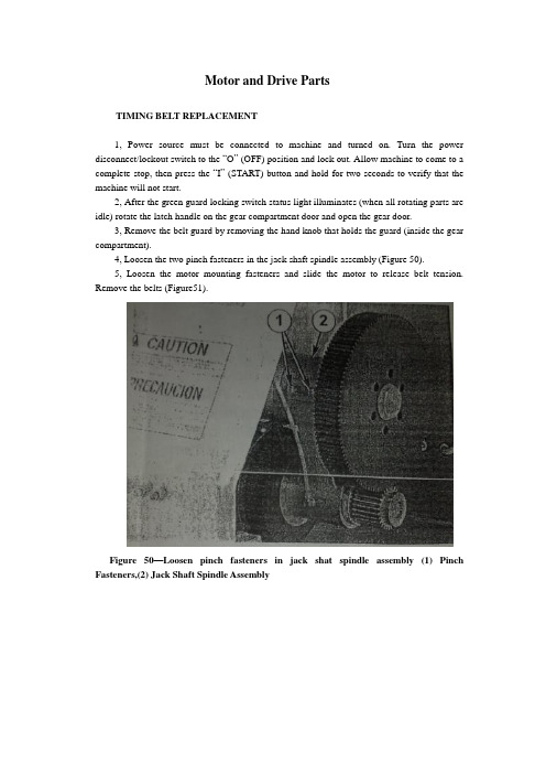
Motor and Drive PartsTIMING BELT REPLACEMENT1, Power source must be connected to machine and turned on. Turn the power disconnect/lockout switch to the “O” (OFF) position and lock out. Allow machine to come to a complete stop, then press the “I” (START) button and hold for two seconds to verify that the machine will not start.2, After the green guard locking switch status light illuminates (when all rotating parts are idle) rotate the latch handle on the gear compartment door and open the gear door.3, Remove the belt guard by removing the hand knob that holds the guard (inside the gear compartment).4, Loosen the two pinch fasteners in the jack shaft spindle assembly (Figure 50).5, Loosen the motor mounting fasteners and slide the motor to release belt tension. Remove the belts (Figure51).Figure 50—Loosen pinch fasteners in jack shat spindle assembly (1) Pinch Fasteners,(2) Jack Shaft Spindle AssemblyFigure 51 – Timing Belts(1)TIMING BELT TENSION1, Use the motor tension wrench to slide the motor and apply tension to the timing belts. The pin on the wrench fits in a hole on the support housing(Figure52). The pinch fasteners in the jack shaft spindle assembly must be properly tension both belts. Tighten the motor mounting fasteners, and then tighten the pinch fasteners in the jack shaft spindle assembly.Figure 52 – Using the motor to apply belt tension. (1) Motor Tension Wrench2, Replace belt guard and tighten with the hand knob.3, Close and rotate latch handle connecting the gear compartment door and support housing.Electrical AssemblyINSPECTIONW ARNING: In the event of an electrical problem, only a qualified electrician should inspect or repair the fault. Voltages dangerous to life exist in the starter enclosure! The power disconnect/lockout switch must be in the “O”(OFF) position. Live voltages are still present in the box even though disconnect is off. Always disconnect and lock out power source before beginning electrical inspection or repair.The electrical assembly must be in good working condition before operating this machine. For a description of the amplifier and safety switch operation and method for checking this system. Electrical schematics are located in the starter enclosure. Refer to Figures53 and 54 and inspect the following:Figure 53 –Starter enclosure interior with variable frequency drive. (1) Disconnect Switch, (2) Guard Locking Switch Power Disconnect, (3) Main Fuses, (4) Earthing Terminals, (5) Transformer, (6) Transformer Fuses Block, (7) Variable Frequency Drive, (8) Contactor, (9) Standstill Monitor, (10) Control RelayFigure 54 – Starter enclosure interior, across-the-line start. (1) Disconnect Switch, (2) Guard Locking Switch Power Disconnect, (3) Main Fuses, (4) Earthing Terminals, (5) Transformer, (6) Transformer Fuse Block, (7) Overload Relay, (8) Contactor, (9) Standstill Monitor, (10) Control RelayStarter enclosure: Inspect interior of starter enclosure for corrosion. If a significant amount of water accumulates in the bottom of the starter enclosure, check the breather drain. Breather drain should be free from obstruction. Excess water could also indicate an opening or loose fitting that allows water to enter the enclosure. Check all access points to the enclosure. Check gasket around door and window. Inspect push/pull stop button, “I”(START) push button assemblies, selector switches and pilot light assembly for damage or corrosion. Replace rubber boots and pilot light lens if damaged.NOTE: Electrical components that fail due to water or chemical contamination are not covered under the warranty.Fuses: Remove transformer fuses, located in the transformer fuse blocks. Check with an ohmmeter or continuity light. If one fuse is replaced, all others of that type fuse should also be replaced.Machines equipped with variable frequency drive(VFD):The drive currently in use is the GPD315/V 7. If the digital display on the drive is not illuminated when the machine is energized, contact Urschel Laboratories.Standstill monitor: Terminals should be tight and free from corrosion. Monitor must be replaced if damaged.Power line filter (CE compliant machine with VFD): See the electrical assemblies illustrations in the “Parts” section of this manual for part locations.Guard locking switches:Replace or straighten actuator key if it is damaged or bent. Check cords for cuts or abrasions. If the green guard locking switch status light does not illuminate when power to the machine is connected, contact Urschel Laboratories. Switch must be replaced if it has been forced open while locked. Use only new screws that are supplied with the switch. Manual release must be in “lock” position when removing and replacing lid( Figure 55).Figure 55 – Guard Locking Switch. (1) Green Guard Locking Switch Status Light, (2) Guard Locking Switch Manual ReleaseGreen status light must be inside the lens when replacing the lid. To maintain watertight features, securely tighten the seven screws for the lid until there is no gap between lid and switch assembly. Do not over tighten.NOTE:The two screws located under the lid on the guard locking switch act as special dowel pins locking the switch assembly into place and must not be substituted.Interrupt switch: Terminals should be tight and free from corrosion. Recommended torque is 5.0 inch pounds (80 inch ounces) or 0.56 Newton-meters. Check sensor, actuator and cord for damage. Switch should be replaced if any defect or damage is defected. Check switch alignment. Actuator must be aligned and within 1/32 (8mm) of sensor to complete safety switch circuit (Figure 56).WARNING: Always perform the guard locking/interrupt switch system test before operating the machine.Figure 56 –Interrupt switch sensor and actuator must be aligned and within 1/32”(8mm). (1) Sensor, (2) ActuatorV ARIABLE FREQUENCY DRIVE PROGRAMMINGA replacement variable frequency drive must have frequencies programmed after the drive has been installed into the electrical enclosure. Refer to the “Speed Chart” on your machine or on page 30 in this manual and program the replacement unit according to the following procedure.WARNING: Starter enclosure must be energized in order to program the drive. Voltages dangerous to life exist when equipment is open and energized! Only a qualified electrician should inspect, install, or program variable frequency drive.1, Turn power disconnect/lockout switch to “O”(OFF). Open starter enclosure door. Operate the power disconnect/lockout switch mechanism in the enclosure to turn power on.2, Set the selector switches to the first drive frequency to be programmed. The frequency drive has a digital operator with a display (Figure 57). The display for the GPD 315/V7 drive will read the lowest setting allowed.Figure 57 – FPD 315 Drive, digital operator. (1) Digital Display,(2) Numeral Change Key, (increase), (3) Numeral Change Key, (decrease), (4) Read/Write Key3, Enter the speed in the display in hertz. Increase or decrease the value with the “numeral change” keys. See the chart for frequency settings.CAUTION: Do not attempt to over speed the motor! Over speeding could create a safety hazard and cause excessive wear on machine parts. Under speeding will cause the motor to overheat.4, With the value correctly displayed and flashing, press the “DATA/ENTER” or “ENTER” key. The display will stop flashing, indicating that the value has been entered.NOTE:Altering preprogrammed speeds will permanently change these values. To return to original settings, follow steps 1-4.5, Operate the power disconnect/lockout switch mechanism in the enclosure to turn power off. Close and lock starter enclosure door.Knife CareKNIFE CARE GUIDELINESKnives should be inspected and sharpened or replaced at regular intervals depending upon operating conditions, type of product and hours of operation. Follow these guidelines for bestresults:1, Do not attempt to remove all defects from the knife edge by sharpening.This practice results in shortened knife life. Small defects will not affect knife performance.2, New knives should not be installed beside worn knives. This arrangement may result in poor quality cuts. Keep all the knives from one spindle in a set and sharpen them together. Periodically check knife width or diameter to make sure all the knives in a set are the same size.3, Recommended minimum dimensions: The following minimum dimensions are intended to give satisfactory results for most applications. However, each customer must look at the quality of cut on his product to determine at what point knives are resharpened beyond usefulness. The minimum dimensions stated are intended to give satisfactory results for most applications. Some customers may be able to give satisfactory results from knives ground smaller, but some may notice a deterioration in quality of out before the minimum size is reached. Measure crosscut knives from the cutting edge to the back of the knife unless otherwise noted; measure the diameter of circular knives unless otherwise noted.SHARPENING EQUIPMENTUrschel Laboratories manufactures machines to quickly and efficiently sharpen knives. The following machine are available;Model WG honing machine is used to sharpen slicing knives and crosscut knives (straight cut only). For the Model DC, use workrest 33224 for 42281 and 42446 crosscut knives and slicing knife insert .Use workrest 33225 for 42460 crosscut knives. Use workrest 33256 for all other slicing knives.Model CKG honing machine is used to place the best possible edge on circular knives. The Model CKG can be purchased from the factory ready to sharpen 3-1/2”circular knives for the Model DC. Honers that are not set up to sharpen 3-1/2” circular knives must have certain parts installed. Use the following procedure:W ARNNING: Honers place an extremely sharp edge on knives; handle knives with care!1, Make sure the honer is unplugged from the power source.2, Install hone assembly, knife holder hub and edge roller stud for 3-1/2’’circular knives (Figure 58). The hone assembly (part number 33083) contains the hone bracket and internal parts, the shield and the honing wheel. The stud on the hone bracket is installed in the second hole from the motor shaft (4” knife position). The knife holder hub (part number 33081) is installed with the raised diameter facing out. The edge roller stud (part number 33023) is installed with the set screw in the second spot drilled hole from the outside end (Note that this part number has remained thesame but the part has been modified. The stud should have four spot drilled holes.) 3, Position the hone shield in as far as possible by loosening the screw and sliding the shield. Retighten the screw.4. Pull the knife clamp hub out of the clamping position. Hold a knife against the knife holder hub. Loosen the set screw in the motor shaft hub and slide the hub and knife on the motor shaft until the knife just touches the honing wheel. Tighten the set screw.5, Adjust the knife clamp if necessary. The knife clamp should hold the knife against the hub tight enough so that it cannot be rotated yet not so tight that it drives the motor back and distorts the base (the brake arm assembly must be properly adjusted to test for knife rotation). To adjust the knife clamp, loosen the two locking nuts and move the clamp in or out.6, Place a knife in the honer and sharpen in the normal manner (see the Model CKG instruction manual for more information). If too much of the knife edge is removed, readjust the hub. If insufficient metal is removed, loosen the screw on the hone shield and slide the hone slightly forward against the knife edge.BUFFINGWARNING: Only qualified trained personnel should buff knives. Use adequate eye and respiratory protection, and a properly guarded buffing wheel. Hold knife securely. Never attempt to catch a dropped knife! Should you drop a knife during the buffing operation, move away and let it tall.When crosscut knives are sharpened by grinding, filing or honing, a slight wire edge may be produced. Buffing will remove this wire edge.Install two to four 10" (254 mm) diameter buffing wheels side by side between flanges at least2" (51 mm) in diameter. Buffing wheels and bars of buffing compound are available from Urschel Laboratories (see “Tools", page67).Turn on the buffer (3600RPM) and hold the bar of buffing compound firmly against the outside diameter of the buffing wheels to apply alight coating of compound. Apply compound frequently to obtain sharp edges quickly.NOTE: If excess compound is applied, the wheel will harden, making it ineffective.Should this occur, Use a buffing wheel rake, available from an industrial supplier, to soften the wheel.When holding knives, be cautions and use a firm grip. Hold the knife firmly with the bevel side up, parallel with and just below the center line of the shaft of the buffer (Figure 58). Push the knife edge into the buffing wheel, penetrating the wheel 1/16"-1/8"(1.5-3mm). Move the knife endwise and buff the entire edge across the buffing wheel with a steady rapid movement in each direction. Several rapid passes are better than one or two slow ones. Do not hold the knife in one area of the buffing wheel too long as the edge may heat and burn. If a burr or wire edge remains, turn the knife over and buff with the bevel side down. Continue buffing, switching from side to side, until wire edge or burr is gone.Sharpen all sides of crinkle knife edges by tipping the knife endwise at a slight angle, first in one direction and then in the other. Next, the knife is held straight and level to buff the remainder of the cutting edge.With bevel side up, sharpen side surface of crinkle knife edge by tipping the knife endwise at a slight angle, first in one direction and then in the other. Next, the knife is held straight and level tobuff the remainder of the cutting edge.Figure 58 –Model CKG honing machine set to sharpen 3-1/2”circular knives (1) Hone Bracket, (2) Mounting Position for Hone Assembly, (3) Knife Holder Hub, (4) Set Screw,(5) Edge Roller Stud (set screw seats in second hole), (6) Hone Shield, (7) Screw, (8) Knife Clamp Hub, (9) Locking Nuts, (10) Honing WheelFailure to obtain sharp edges by buffing may be caused by the following:1, Edges may be too dull or blunt. Blunt edges must always be ground or filed to restore a bevel width and angle similar to that found on a new knife.2, Knives must be correctly held against the buffing wheel (Figure 59).3, Too little or too much buffing compound on the wheel.4, Undersize buffing wheels. Discard the buffing wheels when they are worn to8-3/4" (222 mm) diameter.Figure 59 – Correct position (top) and incorrect position (bottom) for knife during buffing .(1) Knife, (2) Buffing WheelPROBLEM CAUSE CORRECTIONMachine Does Not Start Power disconnect lockout switch isin the "O"(OFF)positionTurn power disconnect lockoutswitch to the "I"(ON) position. Manual release on either of theguard locking switches is in the"unlock" positionTurn manual release to the"lock" position on bothswitches, page 17.Guard locking switch powerdisconnect is in the"O"(OFF)positionTurn guard locking switchpower disconnect to the"I"(ON) position, page 54.Push/pull stop button is not pulledout after being pushedPull push/pull stop button out,page 28.Covers and guards not securelyclosedMake certain covers andguards are securely closed.Check for bent or twistedbrackets that will preventswitches from lining up. See"Covers and Guards",pages34-35.VFD fault or warning Not error code displayed onVFD. Turn disconnect off.电机和传动部件同步带置换1,电源必须与机器连接并打开。
毕业设计毕业论文电气工程及其自动化外文翻译中英文对照

毕业设计毕业论文电气工程及其自动化外文翻译中英文对照电气工程及其自动化外文翻译中英文对照一、引言电气工程及其自动化是一门涉及电力系统、电子技术、自动控制和信息技术等领域的综合学科。
本文将翻译一篇关于电气工程及其自动化的外文文献,并提供中英文对照。
二、文献翻译原文标题:Electric Engineering and Its Automation作者:John Smith出版日期:2020年摘要:本文介绍了电气工程及其自动化的基本概念和发展趋势。
首先,介绍了电气工程的定义和范围。
其次,探讨了电气工程在能源领域的应用,包括电力系统的设计和运行。
然后,介绍了电气工程在电子技术领域的重要性,包括电子设备的设计和制造。
最后,讨论了电气工程与自动控制和信息技术的结合,以及其在工业自动化和智能化领域的应用。
1. 介绍电气工程是一门研究电力系统和电子技术的学科,涉及发电、输电、配电和用电等方面。
电气工程的发展与电力工业的发展密切相关。
随着电力需求的增长和电子技术的进步,电气工程的重要性日益凸显。
2. 电气工程在能源领域的应用电气工程在能源领域的应用主要包括电力系统的设计和运行。
电力系统是由发电厂、输电线路、变电站和配电网络等组成的。
电气工程师负责设计和维护这些设施,以确保电力的可靠供应。
3. 电气工程在电子技术领域的重要性电气工程在电子技术领域的重要性体现在电子设备的设计和制造上。
电子设备包括电脑、手机、电视等消费电子产品,以及工业自动化设备等。
电气工程师需要掌握电子电路设计和数字信号处理等技术,以开发出高性能的电子设备。
4. 电气工程与自动控制和信息技术的结合电气工程与自动控制和信息技术的结合是电气工程及其自动化的核心内容。
自动控制技术可以应用于电力系统的运行和电子设备的控制,以提高系统的稳定性和效率。
信息技术则可以用于数据采集、处理和传输,实现对电力系统和电子设备的远程监控和管理。
5. 电气工程在工业自动化和智能化领域的应用电气工程在工业自动化和智能化领域的应用越来越广泛。
- 1、下载文档前请自行甄别文档内容的完整性,平台不提供额外的编辑、内容补充、找答案等附加服务。
- 2、"仅部分预览"的文档,不可在线预览部分如存在完整性等问题,可反馈申请退款(可完整预览的文档不适用该条件!)。
- 3、如文档侵犯您的权益,请联系客服反馈,我们会尽快为您处理(人工客服工作时间:9:00-18:30)。
毕业论文外文文献翻译译文题目:INTEGRATION OF MACHINERY外文资料翻译资料来源:文章名:INTEGRATION OF MACHINERY 《Digital Image Processing》书刊名:作者:Y. Torres J. J. Pavón I. Nieto and J. A.Rodríguez章节:2.4 INTEGRATION OF MACHINERYINTEGRATION OF MACHINERY (From ELECTRICAL AND MACHINERY INDUSTRY)ABSTRACT Machinery was the modern science and technology development inevitable resultthis article has summarized the integration of machinery technology basic outlineand the development background .Summarized the domestic and foreign integration ofmachinery technology present situation has analyzed the integration of machinerytechnology trend of development. Key word:integration of machinery ,technology,present situation ,productt,echnique of manufacture ,trend of development 0. Introduction modern science and technology unceasing development impelleddifferent discipline intersecting enormously with the seepage has caused the projectdomain technological revolution and the transformation .In mechanical engineeringdomain because the microelectronic technology and the computer technology rapiddevelopment and forms to the mechanical industry seepage the integration of machinerycaused the mechanical industry the technical structure the product organizationthe function and the constitution the production method and the management systemhas had the huge change caused the industrial production to enter into quottheintegration of machineryquot by quotthe machinery electrificationquot for the characteristicdevelopment phase. 1. Integration of machinery outline integration of machinery is refers in theorganization new owner function the power function in the information processingfunction and the control function introduces the electronic technology unifies thesystem the mechanism and the computerization design and the software whichconstitutes always to call. The integration of machinery development also has becomeone to have until now own system new discipline not only develops along with thescience and technology but also entrusts with the new content .But its basiccharacteristic may summarize is: The integration of machinery is embarks from thesystem viewpoint synthesis community technologies and so on utilization mechanicaltechnology microelectronic technology automatic control technology computertechnology information technology sensing observation and control technologyelectric power electronic technology connection technology information conversiontechnology as well as software programming technology according to the systemfunction goal and the optimized organization goal reasonable disposition and thelayout various functions unit in multi-purpose high grade redundant reliable inthe low energy consumption significance realize the specific function value andcauses the overall system optimization the systems engineering technology .From thisproduces functional system then becomes an integration of machinery systematic orthe integration of machinery product. Therefore quotintegration of machineryquot coveringquottechnologyquot and quotproductquot two aspects .Only is the integration of machinerytechnology is based on the above community technology organic fusion one kind ofcomprehensivetechnology but is not mechanical technical the microelectronictechnology as well as other new technical simple combination pieces together .Thisis the integration of machinery and the machinery adds the machinery electrificationwhich the electricity forms in the concept basic difference .The mechanicalengineering technology has the merely technical to develop the machineryelectrification still was the traditional machinery its main function still wasreplaces with the enlargement physical strength .But after develops the integrationof machinery micro electron installment besides may substitute for certainmechanical parts the original function but also can entrust with many new functionslike the automatic detection the automatic reduction information demonstrate therecord the automatic control and the control automatic diagnosis and the protectionautomatically and so on .Not only namely the integration of machinery product ishumans hand and body extending humans sense organ and the brains look has theintellectualized characteristic is the integration of machinery and the machineryelectrification distinguishes in the function essence. 2. Integration of machinery development condition integration of machinerydevelopment may divide into 3 stages roughly.20th century 60s before for the firststage this stage is called the initial stage .In this time the people determinationnot on own initiative uses the electronic technology the preliminary achievement toconsummate the mechanical product the performance .Specially in Second World Warperiod the war has stimulated the mechanical product and the electronic technologyunion these mechanical and electrical union military technology postwar transferscivilly to postwar economical restoration positive function .Developed and thedevelopment at that time generally speaking also is at the spontaneouscondition .Because at that time the electronic technology development not yetachieved certain level mechanical technical and electronic technology union alsonot impossible widespread and thorough development already developed the productwas also unable to promote massively. The 20th century 7080 ages for the second stagemay be called the vigorous development stage .This time the computer technologythe control technology the communication development has laid the technology basefor the integration of machinery development . Large-scale ultra large scaleintegrated circuit and microcomputer swift and violent development has provided thefull material base for the integration of machinery development .This timecharacteristic is :①A mechatronics word first generally is accepted in Japanprobably obtains the quite widespread acknowledgment to 1980s last stages in theworldwide scale ②The integration of machinery technology and the product obtainedthe enormous development ③The various countries start to the integration ofmachinery technology and the product give the very big attention and the support.1990s later periods started the integration of machinery technology the new stagewhich makes great strides forward to the intellectualized direction the integrationof machinery enters the thorough development time .At the same time optics thecommunication and so on entered the integration of machinery processes thetechnology also zhan to appear tiny in the integration of machinery the footappeared the light integration of machinery and the micro integration of machineryand so on the new branch On the other hand to the integration ofmachinery systemmodeling design the analysis and the integrated method the integration ofmachinery discipline system and the trend of development has all conducted thethorough research .At the same time because the hugeprogress which domains and so on artificial intelligence technology neural networktechnology and optical fiber technology obtain opened the development vast worldfor the integration of machinery technology .These research will urge theintegration of machinery further to establish the integrity the foundation and formsthe integrity gradually the scientific system. Our country is only then starts fromthe beginning of 1980s in this aspect to study with the application .The State Councilhad been established the integration of machinery leading group and lists as quot863plansquot this technology .When formulated quot95quot the plan and in 2010 developed thesummary had considered fully on international the influence which and possiblybrought from this about the integration of machinery technology developmenttrend .Many universities colleges and institutes the development facility and somelarge and middle scale enterprises have done the massive work to this technicaldevelopment and the application does not yield certain result but and so on theadvanced countries compared with Japan still has the suitable disparity. 3. Integration of machinery trend of development integrations of machinery arethe collection machinery the electron optics the control the computer theinformation and so on the multi-disciplinary overlapping syntheses its developmentand the progress rely on and promote the correlation technology development and theprogress .Therefore the integration of machinery main development direction is asfollows: 3.1 Intellectualized intellectualizations are 21st century integration ofmachinery technological development important development directions .Theartificial intelligence obtains day by day in the integration of machineryconstructors research takes the robot and the numerical control engine bedintellectualization is the important application .Here said quottheintellectualizationquot is to the machine behavior description is in the control theoryfoundation the absorption artificial intelligence the operations research thecomputer science the fuzzy mathematics the psychology the physiology and the chaosdynamics and so on the new thought the new method simulate the human intelligenceenable it to have abilities and so on judgment inference logical thinkingindependent decision-making obtains the higher control goal in order to .Indeedenable the integration of machinery product to have with the human identicalintelligence is not impossible also is nonessential .But the high performancethe high speed microprocessor enable the integration of machinery product to havepreliminary intelligent or humans partial intelligences then is completelypossible and essential. In the modern manufacture process the information has become the controlmanufacture industry the determining factor moreover is the most active actuationfactor .Enhances the manufacture system information-handling capacity to become themodern manufacture science development a key point .As a result of the manufacturesystem information organization and structure multi-level makes the information thegain the integration and the fusion presents draws up the character informationmeasuremulti-dimensional as well as information organizations multi-level .In themanufacture information structural model manufacture information uniform restraintdissemination processing and magnanimous data aspects and so on manufacture knowledgelibrary management all also wait for further break through. Each kind of artificial intelligence tool and the computation intelligence methodpromoted the manufacture intelligence development in the manufacture widespreadapplication .A kind based on the biological evolution algorithm computationintelligent agent in includes thescheduling problem in the combination optimization solution area of technologyreceives the more and more universal attention hopefully completes the combinationoptimization question when the manufacture the solution speed and the solutionprecision aspect breaks through the question scale in pairs the restriction .Themanufacture intelligence also displays in: The intelligent dispatch the intelligentdesign the intelligent processing the robot study the intelligent control theintelligent craft plan the intelligent diagnosis and so on are various These question key breakthrough may form the product innovation the basicresearch system. Between 2 modern mechanical engineering front science differentscience overlapping fusion will have the new science accumulation the economicaldevelopment and societys progress has had the new request and the expectation tothe science and technology thus will form the front science .The front science alsohas solved and between the solution scientific question border area .The front sciencehas the obvious time domain the domain and the dynamic characteristic .The projectfront science distinguished in the general basic science important characteristicis it has covered the key science and technology question which the project actualappeared. Manufacture system is a complex large-scale system for satisfies the manufacturesystem agility the fast response and fast reorganization ability must profit fromthe information science the life sciences and the social sciences and so on themulti-disciplinary research results the exploration manufacture system newarchitecture the manufacture pattern and the manufacture system effectiveoperational mechanism .Makes the system optimization the organizational structureand the good movement condition is makes the system modeling the simulation andthe optimized essential target .Not only the manufacture system new architecture tomakes the enterprise the agility and may reorganize ability to the demand responseability to have the vital significance moreover to made the enterprise first floorproduction equipment the flexibility and may dynamic reorganization ability set ahigher request .The biological manufacture view more and more many is introduced themanufacture system satisfies the manufacture system new request. The study organizes and circulates method and technique of complicated systemfrom the biological phenomenon is a valid exit which will solve many hard nut tocracks that manufacturing industry face from now on currently .Imitating to livingwhat manufacturing point is mimicry living creature organ of from the organizationfrom match more from growth with from evolution etc. function structure and circulatemode of a kind of manufacturing system and manufacturing process. The manufacturing drives in the mechanism under continuously by ones ownperfect raise on organizing structure and circulating modeand thus to adapt theprocess ofwith ability for the environment .For from descend but the last productproceed together a design and make a craft rules the auto of the distance born producesystem of dynamic state reorganization and product and manufacturing the system tendautomatically excellent provided theories foundation and carry out acondition .Imitate to living a manufacturing to belong to manufacturing science andlife science ofquotthe far good luck is miscellaneous to hand overquot it will produceto the manufacturing industry for 21 centuries huge of influence .机电一体化摘要机电一体化是现代科学技术发展的必然结果本文简述了机电一体化技术的基本概要和发展背景。