ASCO夹管阀资料
ASCO 3 2 阀门指南说明书
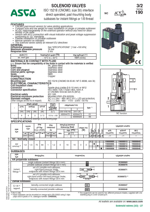
All leaflets are available on: Solenoid valves (3/2) - 27FEATURES• CNOMO pad-mount version for valve piloting applications• Compact size and low weight for easy installation on single or joinable subbases • AC/DC interchangeability of the solenoid operator without any need for disas-sembly of the valve• Version with M12 connection with visual indication and peak voltage suppression conforming to “UL ” standards• Flexible installation on joinable subbases • Manual operator as standard• The solenoid valves satisfy all relevant EU directivesGENERALDifferential pressureSee “SPECIFICATIONS” [1 bar =100 kPa]Maximum allowable pressure 16 bar Response time5 msfluids ( )temperature range (TS)seal materials ( )air, inert gas- 10°C to + 60°CNBR (nitrile)MATERIALS IN CONTACT WITH FLUID( ) Ensure that the compatibility of the fluids in contact with the materials is verified Body P A, glass-filled Core tube Stainless steel Core and plugnut Stainless steel Internal parts, springs Stainless steel Seals NBR Shading coil CopperCONSTRUCTIONMounting padISO 15218 (CNOMO 06-05-80 / NF E 49066, size 30)ELECTRICAL CHARACTERISTICSCoil insulation class F Connector Spade plug (cable Ø 6-10 mm) or M12 Connector specification ISO 4400 / EN 175301-803, form A or CNOMO E03.62.520.N (M12)Electrical safety IEC 335Electrical enclosure protection Moulded IP65 (EN 60529)Standard voltages DC (=): 24V - 48V (M12: 24 V + LED and protection) (Other voltages and 60 Hz on request) AC (~): 24V - 48V - 115V - 230V / 50 Hz-power ratings operator ambient temperature range (TS)replacement coil type (1)inrush~holding ~hot/cold =~=(VA)(VA)(W)(W)(C°)230 V/50 Hz 24 V DC -9433 / 3-10 to + 60430044724300447301-4300552506(1)Refer to the dimensional drawings on the following page.(3)T hese subbases can be mounted on omega rail to EN 50022 using 2 clips (clips sold in packs of 10, catalogue number: 33400036).blanking plug to cover unused port.SOLENOID VALVESISO 15218 (CNOMO, size 30) interface direct operated, pad mounting body subbases for instant fittings or 1/8 threadNC3/2Series 19000421G B -2017/R 01A v a i l a b i l i t y , d e s i g n a n d s p e c i fi c a t i o n s a r e s u b j e c t t o c h a n g e w i t h o u t n o t i c e . A l l r i g h t s r e s e r v e d .All leaflets are available on: 28 - Solenoid valves (3/2)OPTIONS• Explosionproof enclosures for use in zones 1/21-2/22, categories 2-3 to ATEX Directive 2014/34/EU (see “Explosionproof solenoids” section): Ex mb (PV ), PV19000005/6/17/8 / Potentially explosive atmospheres (SG ), zone 22• Straight M12 connector (IP67 protection with connector correctly installed): with 5 m cable: catalogue number 88130212• Right-angle M12 connector (IP67 protection with connector correctly installed), with 5 m cable: catalogue number 88130213• Catalogue number (without connector) + connector catalogue number (with integrated LED indicator and electrical protection ): 24 V (~/=), 88122603 - 48 V (~/=), 88122604 - 115 V (~), 88122605 - 230 V (~), 88122608• M5 flow control regulator to fit port 3, catalogue number: 34600380• Plug with visual indication and peak voltage suppression or with cable length of 2 m (see Solenoids, Coils & Accessories section)INSTALLATION• The solenoid valves can be mounted in any position without affecting operation • Mounting on single or joinable subbases• ATEX 2014/34/EU versions (options “SG” and “PV”) can be installed on single (all versions) or joinable zink diecast subbases • Pipe connections 1/8 have standard thread according to ISO 228/1•Installation/maintenance instructions are included with each valveORDERING EXAMPLES:19000006230V /50 Hz 1900004424V /DCvoltage basic numberoptionsSOLENOID VALVES SERIES 190DIMENSIONS (mm), WEIGHT(kg)TYPE 01- 06Spade plug /M12IEC 335 /EN 175301-803 (11 mm)E03.62.520.N, IP6519000005 to19000045TYPE 02Single instant fitting subbase PolyamideTYPE 04Single subbase Zamak35300047TYPE 03Joinable instant fitting subbase Polyamide 3530007035300071 (set of 2)TYPE 05Joinable subbase Zamak 35300048Right-hand pressure intake option or 2 different pres-sure intakes by procuring the set of two end subbases with endpieces (catalogue number: 35300072).When mounted on DIN rail, it is recommended to use a securing clip on the end subbases as well as on the central subbase.instant-fitting endpieces (catalogue number: 35300071 )2 locking U-piecesO-ringJoinable subbase (catalogue number: 35300070)PolarizerInstant-fitting endpiece(except M12 connection type 06)00421G B -2017/R 01A v a i l a b i l i t y , d e s i g n a n d s p e c i fi c a t i o n s a r e s u b j e c t t o c h a n g e w i t h o u t n o t i c e . A l l r i g h t s r e s e r v e d .1 Manual operator location2 Port 3: M5, depth 5,5 mm3 Mounting: two CM4 x 33,5 screws4 Instant-fitting connection for OD 4 mm tube5 Mounting: two dia. 3,5 mm securing holes, dia. 6,5 mm counter-bores, depth 3,5 mm6 Instant-fitting connection for OD 6 mm tube7 Mounting: two dia. 4,5 mm securing holes8 Adaptable clips9Subbase mounting hole, adapter。
最新asco比例阀汇总
a s c o比例阀Asco比例阀和自己的目标市场,到处乱杀价,其结果是使整个地区的气体价格下滑,使自己原本可以卖得更好一些价格的产品只能低价出售,导致利润下滑。
误区之三:重生产,轻销售。
工业气体的销售是与一般消费品的销售不一样的,它是需要有特殊技能的专业销售。
所以认为生产是很重要的,只要能生产出东西一定能卖得出去,这种经营理念会越来越受到局限。
误区之四:把安全的投入视作是可省的运营成本之一。
安全事故是本行业发展的最大障碍之一,频频发生的气体生产、充装、运输、使用环节中的事故,使气体行业的社会形象受到了很大的负面影响,这对气体行业的远期发展是不利的。
减压阀>>比例式减压阀>>比例式减压阀产品名称:比例式减压阀产品型号:Y43X产品口径:DN25-200产品压力:1.6-6.4Mpa产品材质:铸钢、不锈钢、合金钢等产品概括:生产标准:国家标准GB、机械标准JB、化工标准HG、美标API、ANSI、德标DIN、日本JIS、JPI、英标BS生产。
阀体材质:铜、铸铁、铸钢、碳钢、WCB、WC6、WC9、20#、25#、锻钢、A105、F11、F22、不锈钢、304、304L、316、316L、铬钼钢、低温钢、钛合金钢等。
工作压力1.0Mpa-50.0Mpa。
工作温度:-196℃-650℃。
连接方式:内螺纹、外螺纹、法兰、焊接、对焊、承插焊、卡套、卡箍。
驱动方式:手动、气动、液动、电动。
产品详细信息Y43X比例式减压阀概述我公司生产的比例式减压阀,外形美观、质量可靠,比例准确,工作平稳,既减动压也减静压。
该阀利用阀体内部活塞两端不同截面积产生的压力差,改变阀后的压力,达到减压目的。
我公司减压阀的减压比例是:2∶1,3∶1,4∶1,3∶2,5∶2等,亦可根据用户的要求设计特殊比例的减压阀。
主要技术参数适用介质水、气体适用温度≤90℃压力误差≤8%最小开启压力2∶1 0.2MPa 3∶1 0.3MPa连接形式法兰、内螺纹主要零件材料阀体锡青铜不锈钢铸铁内件锡青铜不锈钢锡青铜或不锈钢主要外形尺寸(法兰连接尺寸PN1.0MPa按GB4216.4-84标准,PN1.6MPa按GB4213.5-84标准)公称通径DN(mm) A D325 232 115/12532 246 140/15040 256 150/15550 270 165/17565 306 185/20080 320 210/230100 340 240/265125 400 275/300150 429 310/350200 358 355/400 型号公称压力公称通径DN(mm)LYB43X-10T (B型)1.050 8565 10280 122100 140 125 160 150 178 200 230YB43X-16T (B型)1.650 8565 10280 122100 140125 160150 178200 230公称通径DN(mm)尺寸(mm)C L D15 1/2" 80 5020 3/4" 80 5025 1" 90 5432 1 1/4" 100 6040 1 1/2" 110 6850 2" 120 80 >>产品中心>>比例式减压阀一、产品[固定比例式减压阀]的详细资料:产品名称:固定比例式减压阀产品特点:本厂生产的比例式减压阀,外形美观,质量可靠,比例准确,工作平稳.既减动压也减静压。
ASCO 产品说明书:单稳态阀门

FEATURES• The monostable spool valves in conformity with IEC 61508 Standard (2010 route 2H version) have TÜV certified with integraty levels: SIL 2 for HFT = 0 / SIL 3 for HFT = 1• All the exhaust ports of the spool valve are connectable, providing betterenvironmental protection. Particularly recommended for sensitive areas, such as clean rooms, and applications in the pharmaceutical and food processing sectors • The valves offer environmental protection against the ingress of liquids, dusts or other foreign matter (environmentally-protected construction)• Can be externally piloted (external air pilot supply) to convert valve to zero minimum operation by flipping a gasket• The solenoid valves satisfy all relevant EU directivesGENERALDifferential pressure 2 - 10,4 bar [1 bar =100 kPa]Flow (Qv at 6 bar)860 l/min (ANR)fluids (✶)temperature range (TS)seal materials (✶)air, inert gas, filtered-40°C to +60°CVMQ (silicone) + PUR (polyurethane)MATERIALS IN CONTACT WITH FLUID(✶) Ensure that the compatibility of the fluids in contact with the materials is verified Body, end covers Brass Spool valve internal parts Brass, stainless steel, POM Core tube Stainless steel Core and plugnut Stainless steel Core spring Stainless steelSeals & discs NBR Top disc P A Disc holder POM Cartridge (low power) Welded, packless AISI 430Seat Brass Seat insert POM Shading coil CopperRider rings (low power) PTFE (NF/WSNF solenoids only)SPECIFICATIONSpipe size orifice size flow coefficientKv operating pressure differential (bar)powerlevel prefix optional solenoidsbasic catalogue numbermin.(2)max. (PS)NEMA ATEX / IECExIP65air (✶)7 & 9Ex db Ex eb mb Ex mb Ex ia-( )(mm)(m 3/h)(l/min)~=~/=EF LPKF NF EM PV (WS)LI -SC Solenoid air pilot operated - spring return (monostable)1/460,7512,50 / 21010BP --l l l --l 551A407 (1)1/460,7512,50 / 21010BP l ------- 551G407 (1)1/460,7512,50 / 21010LP -l l l m m -l 551A307 (1)1/460,7512,50 / 21010LP m ------- 551G307 (1)Solenoid air pilot operated and return (bistable)1/460,7512,50 / 21010BP --l l l --l 551A4081/460,7512,50 / 21010BP l ------- 551G4081/460,7512,50 / 21010LP -l l l m m -l 551A3081/460,7512,50 / 21010LPm-------551G308Select 8 for NPT ANSI 1.20.3 or select G for ISO G (228/1) ● Available feature m Available feature in DC only. - Not available (1) Certified IEC 61508 Functional Safety data, use suffix "SL". (2)Zero minimum is only achieved if external pressure is applied.SOLENOID VALVESpilot operated, spool typesingle/dual solenoid (mono/bistable function )brass body, 1/4NC3/2Series55118/R 01POWER LEVELS - cold electrical holding values (watt)PREFIX TABLEprefixdescription power level1234567LP RP MP BP E F Explosionproof - NEMA 7, 9 - Zinc plated steel conduit m--l E V Explosionproof - NEMA 7, 9 - 316 SS conduit m--l E M Waterproof IP66/67 - Metal enclosure (EN/IEC 60079-7,-18 and -31)*l--lE T Threaded conduit/hole (M20 x 1,5)l--l L P KF Flameproof - Aluminium (EN/IEC 60079-1, 60079-31)*l---N F Flameproof - Aluminium (EN/IEC 60079-1, 60079-31)*l--l P V Encapsulated epoxy moulded (EN/IEC 60079-18)*m--l S C Solenoid with spade plug connector (EN/IEC 60730)l--l W P Waterproof IP67 - Metal enclosure l--l L I I.S. with Aluminium IP66/IP67 enclosure (EN/IEC 60079-11+31)*m---W S Waterproof IP67 - 316 SS enclosure l--l W S L P K F Flameproof 316L SS (EN/IEC 60079-1, 60079-31)*l---W S E M Waterproof IP66/67 - 316 SS enclosure (EN/IEC 60079-0+7+18+31)*l--l W S L I I.S. with 316L SS IP66/IP67 enclosure (EN/IEC 60079-11+31)*m---W S N F Flameproof 316L SS (EN/IEC 60079-1, 60079-31)*l--l T Threaded conduit (1/2" NPT)l--lH T Class H - High temperature, +80°C ambient temp.---lX Other special constructions l--l SUFFIX TABLEsuffixdescription power level1234567LP RP MP BP M O Push type manual operator m/l--l S L Certified IEC 61508 Functional Safety data (2)m/l--l OPTIONS & ACCESSORIESseries pipe size exhaust protector (stainless steel)551G 1/834600418(1) NPT 1/834600482(1) G 1/434600419(1) NPT 1/434600483(1) M534600484(1)l Available featurem Available feature in DC only- Not available* A TEX/IECEx valves using these solenoids are approved according to EN 13463-1 (non electrical)(1)Provided with "SL" suffix(2)Not to use with MO suffixPRODUCT SELECTION GUIDESTEP 1Select basic catalogue number,including pipe thread indentificationletter. Refer to the specifications tableon page: 1Example: G551A407STEP 2Select prefix (combination). Refer tothe specifications table and the prefixtable, respect the indicated powerlevel.Example: EMSTEP 3Select suffix (combination) if required.Refer to the suffix table, respect theindicated power level.Example: MOSTEP 4Select voltage. Refer to standardvoltages on page: 3Example: 230V / 50HzSTEP 5Final catalogue / ordering number.Example:EM G551A407MO 230 V / 50 HzORDERING EXAMPLES VALVES:SC G551 A 407230V/50 HzSC G551 A 407SL230V/50 HzSC G551 A 408MO230V/50 HzSCHT8551 A 408MO230V/50 HzWSLPKF G551 A 307MO24V/DCLPKF G551 A 307MO24V/DCLPKF G551 A 307MO230V/50 HzLI G551 A 30724V/DCWSLI G551 A 308MO24V/DCEM8551 A 407MO230V/50 HzEF G551 H 407MS240V/60 Hzprefix(3)pipe thread voltage basic number(3)suffix(3)P refix EF and EV should always be used in conjunction with change letter Hin the basic number18/R1EXPLANATION OF TEMPERATURE RANGES OF SOLENOID VALVESValve temperature rangeThe valve temperature range (TS) is determined by the selected seal material, the temperature range for proper operation of the valve and sometimes by the fluid (e.g. steam)Operator ambient temperature range The operator ambient temperature range is determined by the selected power level and the safety codeT otal temperature rangeThe temperature range of the complete solenoid valve is determined by the limitations of both temperature ranges aboveELECTRICAL CHARACTERISTICSCoil insulation class FElectrical safety IEC 335Standard voltagesDC (=) 24V - 48VAC (~) 24V - 48V - 115V - 230V (5)/50Hz; other voltages and 60Hz are available on requestprefix optionpower ratings operator ambient temperature range (TS)safety codeelectrical enclosure protection (EN 60529)replacement coil / kit type(2)inrush holding hot/cold ~~=~=(VA)(VA)(W)(W)(C°)(1)230 V/50 Hz 24V/DC Basic power (BP)SC552310,59/11,2-40 to +75EN 60730IP65, moulded 400425-117400425-14201WP/WS 552310,59/11,2-40 to +75EN 60730IP67, steel /SS 400405-117400405-14204NF/WSNF 552310,5--60 to +25/40/60II2G Ex db IIC Gb T6/T5/T4, II2D Ex tb IIIC Db IP66/67, alu./SS 400405-117-02NF/WSNF ---9/11,2-60 to +40/60/75II2G Ex db IIC Gb T6/T5/T4, II2D Ex tb IIIC Db IP66/67, alu./SS -400405-14202EM/WSEM 552310,59/11,2-40 to +40II2G Ex eb mb IIC Gb T3, II2D Ex tb IIIC Db IP66/67, steel /SS 400909-117400913-14204PV 552310,59/11,2-40 to +65II2G Ex mb IIC Gb T3(~)/T4(=), II2D Ex mb IIIC DbIP67, moulded -(4)-(4)05EF/EV552310,59/11,2-40 to +52/40NEMA type 7 and 9NEMA 4X 238614-058238714-00606Low Power (LP)SC 1,51,51,51,7/1,7-40 to +60EN 60730IP65, moulded 400925-097400925-04207WP/WS 1,51,51,51,7/1,7-40 to +60EN 60730IP67, steel /SS 400926-097400926-04209LPKF/WSLPKF(7)2,42,42,4 (8)--40 to +40/65/80II2G Ex db IIB+H2 Gb T6/T5/T4, II2D Ex tb IIIC Db IP66/67, alu./SS - (4)- (4)13LPKF/WSLPKF---0,5/0,5 (7)-40 to +60II2G Ex db IIB+H2 Gb T6, II2D Ex tb IIIC Db IP66/67, alu./SS - (4)- (4)13LPKF/WSLPKF ---2,1 (8)-40 to +40/80II2G Ex db IIB+H2 Gb T6/T4, II2D Ex tb IIIC Db IP66/67, alu./SS - (4)- (4)13NF/WSNF 1,851,851,851,5/1,8-60 to +75/80II2G Ex db IIC Gb T6/T5, II2D Ex tb IIIC Db IP66/67, alu./SS - (4) (5)- (4)08EM/WSEM 1,51,51,51,7/1,7-40 to +40/55II2G Ex eb mb IIC Gb T6/T5, II2D Ex tb IIIC Db IP66/67, steel /SS - (4)- (4)09PV ---1,7/1,7-40 to +65II2G Ex mb IIC Gb T6, II2D Ex mb IIIC DbIP67, moulded -- (4)10EF/EV ---1,7/1,7-40 to +60NEMA type 7 and 9NEMA 4X -- (4)11LI (3) (6)---0,5/0,5-40 to +60II1G Ex ia IIC T6 Ga, II2D Ex tb IIIC Db (6)IP66/67, alu.-- (4)14WSLI (3) (6)---0,5/0,5-40 to +60II1G Ex ia IIC T6 Ga, II2D Ex tb IIIC Db (6)IP66/67, SS-- (4)14prefix optionsafety parameters (1) Temperature range can be limited by sealings(2)Refer to the dimensional drawings on pages: 4 to 7(3) L I/WSLI: Check the electrical characteristics in the corresponding catalogue pages (4) Multiple coil kits are available under A TEX/IECEx, contact us (5) Only available in 24, 48 and 110V/DC (6) L I/WSLI: Low Power, 24 V DC only (LI: For use in zone 0 locations, see the installation conditions given in the I&M instructions )(7)LPKF/WSLPKF: 24 V DC, max. ambient temp. +80°C, contact us (48 V DC = 2,1 W)(8)Max. power ratings values: 115 V AC (2,4 W), 48 V DC (2,1 W)- Not availableU I = (DC)I I P I L I C I (V)(mA)(W)(H)(µF)Low Power (LP)LI/WSLI325001,5ELECTRICAL CONNECTIONSprefixconnectionSCSpade plug connector with cable gland EN175301-803A (ISO 4400) for cables with an outer diameter from 6 to 10 mm WP , WS, EM, WSEMM20 plastics cable gland for cables with an outer diameter from 7 to 12 mm.NF , WSNF , LPKF , WSLPKF 1/2" NPT threaded cable entry. Enclosures are supplied without cable gland PVMoulded-in cable, standard length 2 mLI, WSLI 1/2" NPT threaded cable entry. Enclosures are supplied without cable gland EF , EV1/2" NPT conduits, standard length 35 cmADDITIONAL OPTIONS• Valves configured for external pilot air supply, TPL 20547• Other pipe threads are available on request• Ex mb/mD (prefix "PV") solenoid can be supplied with various cable lengths •Compliance with "UL", "CSA" and other local approvals available on requestINSTALLATION• Multi language installation/maintenance instructions are included with each valve • The solenoid valves can be mounted in any position without affecting operation• Do not connect the pressure supply to the exhaust port 3. The “environmentally-protected” construction is not adapted for a “distributing” function or use in NO function. Contact us for functions available in specific versions• IEC 61508 Functional Safety (suffix SL). Check temperature range of valve body and solenoid for suitability. For probability of failure, contact us• It is necessary to connect pipes or fittings to the exhaust ports to protect the internal parts of the spool valve and its pneumatic operator if used outside or in harsh environments (dusts, liquids etc.)• Threaded pipe connection identifier is 8 = NPT (ANSI 1.20.3); G = G (ISO 228/1)18/R 01DIMENSIONS (mm), WEIGHT (kg)2 mounting holes: 5,3 mm dia.; Spotfacing: 9 mm dia., depth 5 mmTYPE 01:Epoxy mouldedSC: IEC 335 / ISO 4400551A407 / 551A408TYPE 02:Aluminium, epoxy coated / AISI 316L SSNF / WSNF: EN/IEC 60079-1, 60079-31551A407 / 551A408TYPE 04:Metal, epoxy coated / AISI 316L SSWP / WS: IEC 335EM / WSEM: EN/IEC 60079-7+18+31551A407 / 551A408All types18/R1TYPE 05:Epoxy encapsulatedPV: EN/IEC 60079-18551A407 / 551A408TYPE 06:Epoxy encapsulatedEF and EV: NEMA type 7, 9 / ICS-6 ANSI551G407 / 551G408TYPE 07:Epoxy mouldedSC: IEC 335 / ISO 4400TYPE 08:Aluminium, epoxy coated / AISI 316L SSNF / WSNF: EN/IEC 60079-1, 60079-31551A307 / 551A308TYPE 09:Metal, epoxy coated / AISI 316L SSWP / WS: IEC 335EM / WSEM: EN/IEC 60079-7+18+31TYPE 10:Epoxy encapsulatedPV: EN/IEC 60079-1818/R1TYPE 11:Epoxy encapsulatedEF and EV: NEMA type 7, 9 / ICS-6 ANSI551G307 / 551G308TYPE 13:Aluminium, cataphorese black painting / AISI 316L SSLPKF/WSLPKF: EN/IEC 60079-1, 60079-31TYPE 14:Aluminium, cataphorese black painting / AISI 316L SSLI / WSLI: EN/IEC 60079-11, 60079-31551A307 / A308 / A307MO / A308MO551A307 / A308 / A307MO / A308MO18/R1type prefix/option power level A B C D E weight (1)monostable bistable 01SC BP132170102,722,586,50,761,34 02NF BP158224141,8--1,853,51 02WSNF BP158224141,8--3,154,81 04WP / WS / EM / WSEM BP148204103--1,622,22 05PV BP1321728822,567,50,821,45 06EF / EV BP132,517385,522,574,50,641,29 07SC LP132,5173101,522,587,50,971,55 08NF LP158224141,8--1,853,51 08WSNF LP158224141,8--3,154,81 09WP / WS / EM / WSEM LP148204102,2--1,051,70 10PV LP132172100,522,567,51,031,67 11EF/EV LP132,5173100,522,574,50,851,50 13LPKF LP141192113--0,901,62 13WSLPKF LP141192113--1,512,82 14LI LP141192113--0,911,63 14WSLI LP141192113--1,522,83 (1)Incl. coil(s) and connector(s).2Ex d certified cable gland (on request)3Three-core cable, length 2 m4Cable gland for unarmoured cable with 7 to 12 mm dia. sheath6Connector rotatable by 90° increments (cable Ø 6 - 10 mm)8Manual operator location, suffix MO9External pilot air supply, 1/8 pipe sizeConnectable pilot exhaust portNon-connectable pilot exhaust portACCESSORIESø14ø14201/8NPTpilot exhaust protector part number276405-0011/81/41011exhaust protector18/R1e s i g n a n d s p e c i fi c a t i o n s a r e s u b j e c t t o c h a n g e w i t h o u t n o t i c e . A l l r i g h t s r e s e r v e d .18/R 01。
ASCO介绍
空气处理:过滤,调压和润滑
ASCO提供一系列的空气处理元件其中316 SST 过滤调压器特别适用于极其苛刻的环 境应用 .
ASCO 推出系列不锈钢过滤调压器342系列 系列产品。342系列是为客户满足最苛刻的 环境和非常精确的压力调整控制要求而设 计的。342系列不锈钢FRL的内外材料都选 用316L不锈钢,膜片为NBR外涂PTFE以 保证高性能。环境温度-40°C ~+80°C; 满足隔爆区域要求: II 2 G/D c IIC X T85°C (T6) (zone 1-21)
ASCO公司介绍
The RedHat Next Generation 电磁阀的革命性的新电力管理技术极大的提 高了电磁阀的可靠性,大大降低了功耗,为电磁阀工业建立了新的标准。新 的全系列2位2痛,2位3通和2位4通电磁阀可以应用于大多数流体介质控制: •将DC结构的电磁阀的压力提高到AC结构水平(最多较以前提高500%) •低功耗,所有的功耗(基本功耗)全部为2W(例如2W的电磁阀其全部性 能和传统的17W一样) •线圈同时接受AC和DC,电源电压按照世界各地要求分做三个范围:
ASCO的服务
• ASCO的技术服务
– 经过严格培训的ASCO销售和应用工程师对电磁阀产品 有深刻掌握和多年的实际应用工作经验,我们不仅掌 握ASCO的产品知识,我们更通过和用户的合作,深入 了解和掌握用户对电磁阀性能指标的要求,从而为用 户选择最合乎要求的高性价比的电磁阀。 – 我们为您提供这方面的技术支持和咨询服务,为您在 应用方面的问题提出最佳的方案,以使您能够始终保持 竞争优势。 – 针对工程项目,我们根据客户,设计院以及各类需要 使用电磁阀的设备供应商的技术要求,提供性能/价格 最优化的电磁阀选择方案。满足应用要求并且节省项 目投资和运行维护成本。
ASCO电磁阀简介及型号
ASCO 电磁阀ASCO电磁阀、气控阀系列产品在全球首屈一指,经过一世纪,ASCO已成为流体控制应用系统的首选。
公司生产超过3000多种标准电磁阀和20000多个非标准型号。
产品按照最严格的生产规定,在工、商业界应用非常广泛。
主要包括:控制空气、水、轻油、惰性气体、燃油、汽油、蒸汽、真空、超低温、高频率操作、液化气、除尘、自动出售机、腐蚀性介质等。
为了控制各种液态或气态流体和满足各种应用的需要,ASCO-JOUCOM ATIC在电磁阀和机械阀方面,提代了一个广泛的选择,其中流体可以是易燃、易爆介质或腐蚀性介质。
压力可达到150巴,温度可以从-50到300。
口径主要有从1/8英寸到6英寸,操作形式有常闭型,常开型和通用型的2,3,4,5通电磁阀。
通用电磁阀* 热水和蒸汽电磁阀* 用于真空系统的磁磁阀* 用于燃烧系统的电磁阀(介质是油气和燃料油)* 各种工程用电磁阀* NAMUR电磁阀* 用于除尘系统的电磁阀* 用于低温系统的电磁阀* 燃料分配电磁阀(用于各种油料加油机)* 防水锤设计的缓慢关闭式电磁阀* 比例电磁阀* 医药和分析领域用电磁阀* 用于核电厂的电磁阀* 防爆电磁阀美国ASCO电磁阀各种规格型号齐全,二位二通电磁阀:8210系列,8262系列,8263系列,238系列,106系列107系列。
二位三通电磁阀8316系列先导式,8320系列直动式。
二位四通电磁阀:8342系列直动式,8344系列先导式,8345系列先导紧凑型。
二位五通:551系列。
本安型防爆电磁阀:2位2通,2位3通,2位4通。
低功耗电磁阀,手动复位电磁阀:8015系列,8025系列,8037系列8308系列,8310系列,8327系列,8047系列,8408系列,8410系列。
ASCO电磁阀是什么

ASCO电磁阀是什么ASCO电磁阀是什么是以安全保障为前提的阀门,还有一些是压缩气体作为动力源进行控制的阀门,比如今天为大家举例的ASCO电磁阀,就是用来调节管道介质流量、压力、温度等等工艺参数的阀门,它们的特点是控制简单,反应快,而且性能稳定,不需要采取额外的保护措施就会达到不错的效果,那么接下来就和小编一起详细了解下关于这类ASCO电磁阀多方面的信息吧。
相信通过学习这方面的知识可以帮助我们产品的价值。
一、ASCO电磁阀选型建议1、明确气动调节阀在设备或装置中的用途,确定气动调节阀的工作条件:适用介质、工作压力、工作温度等等。
2、确定与气动调节阀连接管道的公称通径和连接方式:法兰、螺纹、焊接等。
3、确定气动调节阀的型式ASCO电磁阀等。
4、确定动作方式可分为:直行程和角行程两种方式。
5、选择ASCO电磁阀的种类:闭路气动调节阀、调节气动调节阀、安全气动调节阀等。
6、确定ASCO电磁阀的参数:对于自动气动调节阀,根据不同需要先确定允许流阻、排放能力、背压等,再确定管道的公称通径和阀座孔的直径。
7、确定操作ASCO电磁阀的方式:手动、电动、电磁、气动或液动、电气联动或电液联动等。
8、根据管线输送的介质、工作压力、工作温度确定所选气动调节阀的壳体和内件的材料:灰铸铁、可锻铸铁、球墨铸铁、碳素钢、合金钢、不锈耐酸钢、铜合金等。
二、ASCO电磁阀的工作原理ASCO电磁阀就是以压缩气体为动力源,以气缸为执行器,并借助于阀门定位器、转换器、电磁阀、保位阀、储气罐、气体过滤器等附件去驱动阀门,实现开关量或比例式调节,接收工业自动化控制系统的控制信号来完成调节管道介质的:流量、压力、温度、液位等各种工艺过程参数。
气动调节阀的特点就是控制简单,反应快速,且本质安全,不需另外再采取防爆措施。
以上为大家具体介绍的是关于气动调节阀多方面的知识,由此可以得知这些产品通过压缩气体为动力源,能够调节管道介质的流量、压力、温度等工艺过程参数,除此之外,气动调节阀可以提供多种多样尺寸规格的选择。
ASCO电磁阀产品说明

电气接线
NA NB
Eex d ⅡC
T3, T4, T5
-40~+40℃ IP 65
不锈钢 铸铁
M20×1.5
NK Eex d ⅡB + H2
NF NL
Eex d ⅡC T4, T5, T6
IP 67
-20~+60℃
铝
-60~+100℃铸铁,表面镀锌 1/2 NPT螺纹(M20×1.5可选)
WSNF
不锈钢
ASCO 产品培训
FY07 training
ASCO 美国产品系列
ASCO products are specified for the control of fluids and gases for a wide range of industries and applications
ASCO 小红帽电磁阀
Zone 21 or 22
Zone 20 : Continuously present (during long periods), > 1000 hours/year
Zone 21 : Not likely to be present (regular services) > 10 – 1000 hours/year
Zone 20
Zone 22 : Accidentally present (shorttime-service- never in regular service) < 10 hours/year
电气防爆基础
温度等级
I组
温度 < 150°C or < 450°C 根据设备上积聚的煤矿粉尘
II 组
丙酮
乙酸
asco阀门安全仪表系统用电磁阀使用手册-iec 61508说明书

I&M V 9629 R6 Solenoid Valves used in SafetyInstrumented SystemsASCO Valves ®Page 1 of 7Table of Contents1 I ntroduction (3)1.1 Terms and Abbreviations (3)1.2 Acronyms (3)2 Designing a Safety Instrumented Function using an ASCO Solenoid Valve (4)2.1 Safety Function (4)2.2 Environmental limits (4)2.3 Application limits (4)2.4 Design Verification (4)2.5 SIL Capability (5)2.5.1 Systematic Integrity (5)2.5.2 Random Integrity (5)3 Installation and Commissioning (5)3.1 Installation (5)3.2 Response Time (6)4 Operation and Maintenance (6)4.1 Proof test without automatic testing (6)4.2 Proof test with automatic partial valve stroke testing (6)4.3 Repair and replacement (7)4.4 ASCO Notification (7)5 ASCO Solenoid Pilot Valves Covered (7)6 Status of the document (7)6.1 Releases (7)1 IntroductionThis Operating Manual provides the necessary information to design, install, verify and maintain a Safety Instrumented Function (SIF) utilizing an ASCO Solenoid Valve. This manual provides necessary requirements for meeting the IEC 61508 or IEC 61511 functional safety standards.1.1 Terms and Abbreviations• Process Valve Any valve that is used to control the flow of media being used in a process.For the purpose of this document, this is usually a 2-way valve whosemovement is being controlled by an actuator and pilot valve.• Pilot Valve A 3-way or 4-way valve that is used to send or remove pressurized mediato and from an actuator for the opening and closing of a process valve.• Direct Acting Refers to a solenoid valves main orifice that is opened and closed as adirect result of the solenoid valves electromagnetic movement when thecoil is energized and de-energized.• Indirect Acting Refers to a solenoid valve’s main orifice that is opened and closed as aresult of fluid flow being directed from the electromagnetic 3-way solenoidpilot.• Safety Freedom from unacceptable risk of harm• Functional Safety The ability of a system to carry out the actions necessary to achieve or tomaintain a defined safe state for the equipment / machinery / plant /apparatus under control of the system• Basic Safety The equipment must be designed and manufactured such that it protectsagainst risk of damage to persons by electrical shock and other hazardsand against resulting fire and explosion. The protection must be effectiveunder all conditions of the nominal operation and under single faultcondition• Safety Assessment The investigation to arrive at a judgment - based on evidence - of thesafety achieved by safety-related systems• Fail-Safe State The state where the solenoid is de-energized and its return spring holdsthe pilot in the closed position.• Fail Safe Failure that causes the valve to go to the defined fail-safe state without ademand from the process.• Fail Dangerous Failure that does not respond to a demand from the process (i.e. beingunable to go to the defined fail-safe state).• Fail Dangerous Undetected (DU) Failure that is dangerous and that is not being diagnosed byautomatic stroke testing.• Fail Dangerous Detected (DD) Failure that is dangerous but is detected by automatic stroke testing.• Fail No Effect Failure of a component that is part of the safety function but that has noeffect on the safety function.• Low Demand Mode Mode, where the frequency of demands for operation made on a safety-related system is no greater than twice the proof test frequency.1.2 Acronyms• FMEDA Failure Modes, Effects and Diagnostic Analysis• HFT Hardware Fault Tolerance• MOC Management of Change: These are specific procedures often done whenperforming any work activities in compliance with government regulatoryauthorities.• PFD AVG Average Probability of Failure on Demand• SFF Safe Failure Fraction, the fraction of the overall failure rate of a device thatresults in either a safe fault or a diagnosed unsafe fault.• SIF Safety Instrumented Function, a set of equipment intended to reduce therisk due to a specific hazard (a safety loop).• SIL Safety Integrity Level, discrete level (one out of a possible four) forspecifying the safety integrity requirements of the safety functions to beallocated to the E/E/PE safety-related systems where Safety Integrity Level4 has the highest level of safety integrity and Safety Integrity Level 1 hasthe lowest.• SIS Safety Instrumented System – Implementation of one or more SafetyInstrumented Functions. A SIS is composed of any combination ofsensor(s), logic solver(s), and final element(s).2 D esigning a Safety Instrumented Function (SIF) using an ASCOSolenoid Valve2.1 Safety FunctionWhen de-energized, the ASCO Solenoid Pilot Valve moves to its fail-safe position. Depending on the solenoid specified Normally Closed (NC) or Normally Open (NO), the valve will supply the fluid media or vent the fluid media depending on the piping of the installation. Please note that the solenoid pilot valve must be piped to the actuator in accordance with the manufacturer’s recommendations and allowable desired function.The valve is intended to be part of final element subsystem as defined per IEC 61508 and the achieved SIL level of the designed function must be verified by the designer.2.2 Environmental limitsThe environmental limits of each solenoid are specified in the products respective catalog and Installation & Maintenance Instructions. The designer of a SIF must check that the product is rated for use within the expected environmental limits.2.3 Application limitsThe application limits of an ASCO Solenoid are specified in the products respective catalog and Installation & Maintenance Instructions. It is especially important that the designer check for material compatibility considering on-site chemical contaminants and air supply conditions. If the solenoid valve is used outside of the application limits or with incompatible materials, the reliability data provided becomes invalid.2.4 Design Verification• A detailed Failure Mode, Effects, and Diagnostics Analysis (FMEDA) report is available from ASCO.This report details all failure rates and failure modes as well as the expected lifetime.•The achieved Safety Integrity Level (SIL) of an entire Safety Instrumented Function (SIF) design must be verified by the designer via a calculation of PFD avg considering redundant architectures, proof test interval, proof test effectiveness, any automatic diagnostics, average repair time and the specific failure rates of all products included in the SIF. Each subsystem must be checked to assure compliance with minimum hardware fault tolerance (HFT) requirements. The Exida exSILentia tool is recommended for this work.•When using an ASCO Solenoid in a redundant configuration, a common cause factor of 5% should be included in safety integrity calculations.•The failure rate data listed the FMEDA report is only valid for the useful life time of an ASCO Solenoid.The failure rates will increase sometime after this time period. Reliability calculations based on the data listed in the FMEDA report for mission times beyond the lifetime may yield results that are too optimistic, i.e. the calculated Safety Integrity Level will not be achieved.2.5 SIL Capability2.5.1 Systematic IntegrityThe product has met manufacturer design process requirements of Safety Integrity Level (SIL) 3. These are intended to achieve sufficient integrity against systematic errors of design by the manufacturer. A Safety Instrumented Function (SIF) designed with this product must not be used at a SIL level higher than the statement without “prior use” justification by end user or diverse technology redundancy in the design.2.5.2 Random IntegrityThe solenoid valve is a Type A Device. Therefore when used the only component in a final element subassembly, a design can meet SIL 3 @ HFT=1 and SIL 2 @ HFT=0.When the final element assembly consists of many components (solenoid valve, quick exhaust valve, actuator, isolation valve, etc.) the SIL must be verified for the entire assembly using failure rates from all components. This analysis must account for any hardware fault tolerance and architecture constraints.3 Installation and Commissioning3.1 Installation•The ASCO Solenoid valve must be installed per standard installation practices outlined in the Installation Manual.•The environment must be checked to verify that environmental conditions do not exceed the ratings.•The ASCO Solenoid must be accessible for physical inspection.•Instrument Air Filtration: These solenoids are intended for use on clean, dry air or inert gas filtered to50 microns or better. To prevent freezing, the dew point of the media should be at least 18°F(10°C)below the minimum temperature to which any portion of the clean air or gas system could be exposed.Instrument air in compliance with ANSI/ISA Standard S7.3-1975 (R1981) exceeds the above requirements and is, therefore, an acceptable medium for these valves.• It is the operator’s responsibility to only use design options such as latches, when it is safe to do so.• Typical 3-way pilot valve piping configurations:a. 1 out-of 1 – This is the most common pilot valve configuration used.b. 2 out-of 2 – This is commonly used for high availability applications. In the case that onesolenoid valve was to spuriously trip, the second solenoid still maintains the position of theactuator/process valve at its operating state. Both solenoids must close in order to shift theactuator/process valve to its non-operating state.3.2 Response TimeThe response time of a solenoid pilot valve will vary by design. The factors that affect response time are pilot valve orifice size, operating pressure, size of actuator, torque required to open and close process valve, and distance between pilot valve and actuator. It is the responsibility of the end user to use a pilot valve that delivers the correct opening and closing time of the process valve required for the application.4 Operation and Maintenance4.1 Proof test without automatic testingThe objective of proof testing is to detect failures within an ASCO Solenoid that are not detected by any automatic diagnostics of the system. Of main concern are undetected failures that prevent the safety instrumented function from performing its intended function.The frequency of proof testing, or the proof test interval, is to be determined in reliability calculations for the safety instrumented functions for which an ASCO Solenoid is applied. The proof tests must be performed more frequently than or as frequently as specified in the calculation in order to maintain the required safety integrity of the safety instrumented function.The following proof test is recommended. Any failures that are detected and that compromise functional safety should be reported to ASCO.Table 11Bypass the safety PLC or take other appropriate action to avoid a false trip, following company Management of Change (MOC) procedures2Inspect the external parts of the solenoid valve for dirty or clogged ports and other physical damage. Do not attempt disassembly of the valve.the 3De-energize the solenoid coil and observe that the actuator and valve move. Energize solenoid after a small movement of the valve.4Inspect the solenoid for dirt, corrosion or excessive moisture. Clean if necessary and take corrective action to properly clean the air supply. This is done to avoid incipient failures due todirty air.5Record a n y failures i n your c o m p a n y’s S I F i n s p e c t i o n d a t a b a s e. Restore the loop t o full operation.6Remove the bypass from the safety PLC or otherwise restore normal operationThis test will detect approximately 99% of possible DU failures in the solenoid (Proof Test Coverage).The person(s) performing the proof test of an ASCO Solenoid should be trained in SIS operations, including bypass procedures, solenoid maintenance and company Management of Change procedures. No special tools are required.4.2 Proof test with automatic partial valve stroke testingAn automatic partial valve stroke testing scheme that performs a full stroke of the solenoid valve and measures valve movement timing will detect most potentially dangerous failure modes. It is recommended that a physical inspection (Step 2 from Table 1) be performed on a periodic basis with the time interval determined by plant conditions. Maximum inspection interval is five years but an annual inspection is recommended.4.3 Repair and replacementAccording to section 7.4.7.4 of IEC 61508-2 a useful lifetime based on experience, should be assumed. General field knowledge suggests that most solenoid valves have a useful life of 3 to 10 years, but may be longer depending on the valve series and other factors.It is the responsibility of the end user to establish a preventative maintenance process to replace all solenoids before the end of the useful life.4.4 ASCO NotificationAny failures that are detected and that compromise functional safety should be reported to ASCO Valve. Please contact ASCO customer service.5 ASCO Solenoid Pilot Valves CoveredSelect ASCO valves from the following series have been evaluated per IEC 61508 parts 1 and 2 and covered under this document:∙8314 Series - 3-Way Direct Acting Pilot Valves∙8320 Series - 3-Way Direct Acting Pilot Valves∙8316 Series - 3-Way Indirect Acting Pilot Valves∙551, 552, 553 Series - 3 and 4-Way Indirect Acting Pilot Valves∙8317, 8320, 8321 Series - 3-Way Harsh Environment Pilot Valves∙327/8327 Series - 3-Way Direct Acting Pilot Valves.∙126 Series - 3-Way Direct Acting Pilot Valves.∙8317 Series – 3-Way Piloting Quick Exhaust valve∙307 Series - 3-Way Direct Acting Pilot Valves∙364 Series – 3-Way Spool Valves∙362/562 Series – 3-Way and 4-Way Spool Valves6 Status of the document6.1 ReleasesRevision: GECN Number: 264756Release status: V9629 Initial Release on 02/18/11。
- 1、下载文档前请自行甄别文档内容的完整性,平台不提供额外的编辑、内容补充、找答案等附加服务。
- 2、"仅部分预览"的文档,不可在线预览部分如存在完整性等问题,可反馈申请退款(可完整预览的文档不适用该条件!)。
- 3、如文档侵犯您的权益,请联系客服反馈,我们会尽快为您处理(人工客服工作时间:9:00-18:30)。
SIRAI ELETTROMECCANICA S.r.l. - BUSSERO (MI) – Italy - Tel. (+39) 02950371 - Fax (+39) 029******* – E-mail: info@ -
PINCH SOLENOID VALVE S106 2/2 – NC (Normally closed)
f GENERAL FEATURES f MATERIALS
Pinch solenoid valve, suitable to shut off media without producing Body Anodized aluminum neither turbulent flows nor dead spaces. Pinching device POM (reinforced acetal copolymer) High flow rate under the same conditions of internal diameter of Internal components Stainless steel different solenoid valves; the system allows a bi-directional through flow. Core tube Stainless steel The valves are suitable for soft SILICONE tubings or others, similar
as to elasticity and hardness (50 shore A). f COIL
The tubing is the only material in contact with the fluid. Continuous duty ED 100% The tubings are not included in our supply. Encapsulation material PET (polyethylene terephftalate) fiberglass reinforced Insulation class F (140°C) f INSTALLATION Ambient temperature -10 C° +60 °C Solenoid valve can be mounted in any position. Electric connection DIN 46340- 3 poles plug-connectors (DIN 43650) Protection degree IP 65 (DIN 40050) with plug-connectors Voltages DC 12-24V (+10% -5%) (Other voltages on request).
TUBINGS Series and type I.D. (mm) O.D. (mm) Pinching strength (kg) Valve Coil Power absorption
(W) Notes Weight (kg) 4,8 7,9 1,100 S106-08
6,4 9,5 1,400 S106-09 Z130A 13 - 0,440
f NOTE
- For the use of a soft tubing with outside diameter smaller than 6mm it is necessary to install the tubing guide sleeve (drawing K29501). T H E V A L I D I T Y O F R E P O R T E D D A T A I S R E F E R R E D T O T H E D A T E O F I S S U E . P O S S I B L E U P D A T I N G A R E A V A I L A B L E O N R E Q U E S T - In case the tubing is not placed in its seat, the solenoid valve could operate incorrectly.
0402/0406。