外文翻译--在核聚变实验中的远程控制仿真平台
外文翻译+原文
MATALAB 混合仿真平台控制算法的概述MATALB混合仿真平台,即为将硬件引入到仿真回路里的半实物仿真系统,可用于过程控制器的开发与测试。
平台提供了三种控制器的嵌入方法,尤其能用Matlab 语言编写,大大提高了平台的灵活性。
为了建立过程控制混合仿真试验系统,必须解决PC 机作为虚拟控制器设计环境的实现和在Windows 操作系统中实时控制的实现这两个问题。
我们先详细阐述过程控制混合仿真试验系统的实现原理;最后介绍平台控制算法的嵌入方法,并通过实验仿真验证平台的有效性。
过程控制混合仿真平台实现原理:(1)数值计算,MATLAB提供了大约600多个数学和工程上常用的函数。
这些函数的数值运算是针对矩阵操作优化过的,可以使用它来代替底层编程语言。
在保持同样性能的情况下,编程工作量非常小,数值计算采用了LAPACK,BLAS,FFTW等优秀数学函数库,使得计算效率得到进一步的提升。
MATLAB 包含的主要数学函数有线性代数和矩阵运算、傅立叶变换和统计分析、微分方程求解、稀疏矩阵运算以及三角和其他初等数学运算等;除此之外,随着Matlab的应用领域不断的扩大,补充了用于许多特定领域的函数。
(2)算法开发,强大的计算能力,方便易用的编程语言和丰富的数学函数使MATLAB最适于用于算法开发工作。
典型的应用包括:数据分析,信号处理,图像处理,系统建模和高级算法研究等。
不管用户是使用已有的算法,还是自行开发,MATLAB提供了一个通用的平台。
使用MATLAB进行算法开发就像平时书写数学表达式一样。
将用户在MATLAB 中开发的算法结合到外部运行的系统中。
一旦用户的算法和仿真经过了编写和调试,MATLAB Compiler和C/C++ Math Library 会将MATLAB应用自动转换成可移植C 和C++代码的工具。
对于信号处理,控制系统设计和其他一些应用,MATLAB工具箱提供了一系列先进的技术。
工具箱远远超出了提供一些基本算法的范畴:他们提供了一个学习,研究,创新前沿理论和技术的舞台。
中文版ExploringChemistrywithElectronicStructureMethos

———————————————————————————————— 作者: ———————————————————————————————— 日期:
Exploring Chemistry with Electronic Structure M ethod
3.3 寻找过渡态 .................................................................................... 错误!未定义书签。 3.4 难处理的优化 .............................................................................. 错误!未定义书签。 第四章 频率分析ﻩ错误!未定义书签。 4.1 预测红外和拉曼光谱ﻩ错误!未定义书签。
频率计算的输入 ...................................................................... 错误!未定义书签。 频率和强度ﻩ错误!未定义书签。 矫正因子和零点能。ﻩ错误!未定义书签。 简正模式ﻩ错误!未定义书签。 热力学 ...................................................................................... 错误!未定义书签。 零点能(Zero Point Energy)和内能(Thermal Energy)错误!未定义书签。 极化率和超极化率 .................................................................. 错误!未定义书签。 4.2 表征稳定点ﻩ错误!未定义书签。 下面列出了需要描述稳定点时必须考虑的问题ﻩ错误!未定义书签。 第五章 基组的影响........................................................................................... 错误!未定义书签。 5.1 最小基组ﻩ错误!未定义书签。 5.2 分裂基组ﻩ错误!未定义书签。 5.3 极化基组 .................................................................................. 错误!未定义书签。 5.4 弥散函数(Diffuse Functions)ﻩ错误!未定义书签。 5.5 高角动量基组22ﻩ 5.6 第三周期以后的原子的基组ﻩ错误!未定义书签。 第六章 选择合适的理论模型ﻩ错误!未定义书签。 6.1使用半经验方法 ......................................................................... 错误!未定义书签。 半经验方法的局限性 .............................................................. 错误!未定义书签。 6.2 电子相关和后 SCF 方法............................................................错误!未定义书签。 Hartree-Fock 理论的限制ﻩ错误!未定义书签。 MPn方法ﻩ错误!未定义书签。 6.3 耦合簇(Coupled CLuster)和二次结构相关(Quadratic Configura tionInteraction)方法................................................................ 错误!未定义书签。 密度泛函方法 .......................................................................... 错误!未定义书签。 6.4 资源的使用ﻩ错误!未定义书签。 第七章 高精度能量模型................................................................................... 错误!未定义书签。 7.1 预测热化学 ................................................................................ 错误!未定义书签。 原子化能ﻩ错误!未定义书签。 电子亲和势 .............................................................................. 错误!未定义书签。 离子化能ﻩ错误!未定义书签。 质子亲和能ﻩ错误!未定义书签。 7.2 理论模型的评价ﻩ错误!未定义书签。 7.3 G2 分子基(Molecule Set)以及缺陷及对缺陷的解释ﻩ错误!未定义书签。
JUMO dTRAN S 压力传感器说明书
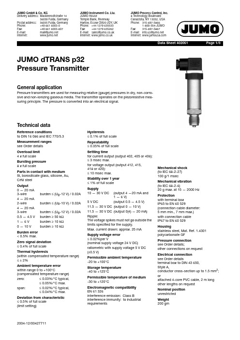
Data S heet 402051Page 1/3 JUMO dTRAN S p32Pre ss ure Tran s mitterG eneral applicationPressure transmitters are used for measuring relative (gauge) pressures in dry, non-corro-sive and non-ionizing gaseous media. The transmitter operates on the piezoresistive mea-suring principle. The pressure is converted into an electrical signal.Technical dataReference condition sto DIN 16086 and IEC 770/5.3Mea s urement range ssee Order detailsOverload limit4 x full scaleBur s ting pre ss ure8 x full scalePart s in contact with mediumSi, borosilicate glass, silicone, Au,CrNi steelOutput0—20mA3-wire burden ≤ (U B-12V) / 0.02A 4—20mA2-wire burden ≤ (U B-10V) / 0.02A 4—20mA3-wire burden ≤ (U B-12V) / 0.02A 0.5—4.5V burden ≥ 50kΩ1—6V burden ≥ 10kΩ0—10V burden ≥ 10kΩBurden error< 0.5% max.Zero s ignal deviation≤ 0.4% of full scaleThermal hy s tere s i s(within compensated temperature range)≤± 2%Ambient temperature errorwithin range 0to+100°C (compensated temperature range) zero:≤ 0.03%/°C typical,≤ 0.05%/°C max.span:≤ 0.02%/°C typical,≤ 0.04%/°C max. Deviation from characteri s tic≤ 0.5% of full scale(limit setting)Hy s tere s i s≤ 0.1% of full scaleRepeatability≤ 0.05% of full scaleS ettling timefor current output (output 402, 405 or 406):≤ 3msec max.for voltage output (output 412, 415,418 or 420):≤ 10msec max.S tability over 1 year≤ 1% of full scaleS upply10—30V DC(output 4—20mA and1—6V)5V DC (output0.5—4.5V)11.5—30V DC(output 0—10V)11.5—30V DC(output 0(4)—20mA)Ripple:The voltage spikes must not go outside thelimits specified for the supply.Max. current drawn: approx. 25mAS upply voltage error≤ 0.02%per V(nominal supply voltage 24V DC)ratiometric with supply voltage 5V DC(±0.5V)Permi ss ible ambient temperature-20to+100°CS torage temperature-40to+125°CPermi ss ible temperature of medium-30to+120°CElectromagnetic compatibilityEN 61 326interference emission:Class Binterference immunity:to industrialrequirementsMechanical s hoc k(to IEC 68-2-27)100g/1msecMechanical vibration(to IEC 68-2-6)20g max. at 15—2000HzProtectionwith terminal boxIP65 to EN 60529(connection cable diameter:5mm min., 7mm max.)with connection cableIP67 to EN 60529Hou s ingstainless steel, Mat. Ref. 1.4301polycarbonate GFPre ss ure connectionsee Order details;other connections on requestElectrical connectionsee Order detailsterminal box to DIN 43650,Style A,conductor cross-section up to 1.5mm2;orattached 4-core PVC cable, 2m longother lengths on requestNominal po s itionunrestrictedWeight200gmData S heet 40.2051Page 2/3Dimen s ion sElectrical connectionCaution:Earth the instrument!(pressure connection and / oror screenConnectionTerminalsConnector Cable Supply10—30V DC 11.5—30V DC 5V DC 1 L+2 L-white grayOutput 1—6V 0—10V 0.5—4.5V2 -3 +gray yellowOutput 4—20mA, 2-wire1 +2 -white grayproportional 4 to 20mA currentin supplyOutput 0(4)—20mA, 3-wire2 -3 +gray yellowProtective earth conductorScreenblackData S heet 40.2051Page 3/3Order detail sBa s ic type402051Pressure transmitter JUMO dTRANS p32I Ba s ic type e x ten s ionI/000noneI/034Sensor mit GelvorlageI/999special versionI I InputI I4110 40 mbar gauge pressureI I4130 60 mbar gauge pressureI I4140 100 mbar gauge pressureI I4150 160 mbar gauge pressureI I4510 0.25 bar gauge pressureI I4520 0.4 bar gauge pressureI I4530 0.6 bar gauge pressureI I999special gauge pressure rangeI I I OutputI I I4020 to 20mA 3-wireI I I405 4 to 20mA 2-wireI I I406 4 to 20mA 3-wireI I I4120.5 to 4.5V 3-wireI I I4150 to 10V 3-wireI I I418 1 to 5V 3-wireI I I420 1 to 6V 3-wireI I I I Proce ss connection (not front-flu s h)I I I I501pressure connection G 1/8 to EN 837I I I I502pressure connection G 1/4 to EN 837I I I I504pressure connection G 1/2 to EN 837 (standard connection)I I I I510pressure connection 1/8-27 NPT to DIN 837I I I I511pressure connection 1/4-18 NPT to DIN 837I I I I692 6 mm hose connectionI I I I Material of proce ss connectionI I I I I20stainless steelI I I I I I Electrical connectionI I I I I I12by attached cable (cable length in plain text)I I I I I I36by circular connector M12 x 1I I I I I I61by terminal boxI I I I I I I402051/----20-Order code。
我的愿望 可控核聚变英语作文

我的愿望可控核聚变英语作文English:My biggest wish is to see the development of controllable nuclear fusion technology in my lifetime. This revolutionary form of energy production has the potential to provide a clean, abundant, and sustainable source of power for the world. The ability to harness the power of the sun and stars here on Earth would completely transform our energy landscape, reducing our dependence on fossil fuels and mitigating the effects of climate change. The advancements being made in fusion research are incredibly exciting, with projects like ITER and SPARC getting closer to achieving practical fusion energy. I dream of a future where fusion power plants are a reality, providing clean energy to communities around the globe, and ushering in a new era of sustainable development. It is my hope that through continued research and investment, we can overcome the technical challenges and make controlled nuclear fusion a viable energy solution for generations to come.中文翻译:我最大的愿望是在我的有生之年看到可控核聚变技术的发展。
基于Visio的核电仪控设计出图仿真工具的开发
绘图软件Visio 是目前核电仪控系统设计阶段绘制控制逻辑图的主要工具。
若要对设计绘制出的Visio 图进行逻辑组态功能调试验证,通常需交付相关仿真平台(如RINSIM [1]等系统)。
通过这些工业级别的仿真平台对仪控系统进行组态验证分析这一过程十分复杂,要经过图形转换、数据库加点、连接数学模型、开发通信程序等步骤,过程繁琐,无法满足快速验证局部系统正确性、灵活修改系统参数的要求。
本文结合核电仪控设计在出图前能对系统局部仿真以验证系统功能的实际需求,基于Visio 的Automation 技术实现了Visio 界面与后台程序之间的数据交互,开发Visio 软件出图的仿真功能,为设计阶段快速出图、即时仿真提供了新工具。
1Visio 二次开发Visio 的二次开发能力也称为Automation ,是基于COM (组件对象模型)的一种不同程序相互集成的技术[2]。
它允许开发人员使用VB 、C 、C ++等支持Automation 的编程语言编写程序嵌入到Visio 软件中,也允许将Visio 作为图形引擎,嵌入到外部软件中,从而缩短开发周期。
开发人员可以通过创建Visio 加载项(Add -on )的方式扩展Visio 的功能,这种机制可以通过以下两种方法来实现:①使用C /C++等语言编写VSL 代码并编译成.vsl 文件;②使用任意可创建.exe 自动化客户端的语言编写代码并生成独立的可执行文件。
其中,VSL 实际上就是Visio 专用的一种动态链接库(DLL )[2]。
当Visio 在文件路径或启动项中搜索到.vsl 环境配置文件时,会自动将该文件加载到Visio 实例的进程空间中,因此.vsl 文件在Visio 进程内运行,而.exe 文件在Visio 进程外独立运行,这也是两种Add-on 加载项实现方法的最根本的区别。
本文采用VSL 方法对Visio 软件进行二次开发,具有扩展性强、交互能力强和运行效率高等优点。
mit bevfusion 原理讲解

mit bevfusion 原理讲解MIT核聚变是一种实现可控核聚变的技术,被认为是未来清洁能源的重要解决方案之一。
在MIT核聚变实验室中,研究人员正在开发一种新型的核聚变装置,称为MIT BevFusion。
本文将介绍MIT BevFusion的原理和工作原理。
MIT BevFusion的原理基于磁约束聚变技术,该技术利用强磁场将等离子体困在一个狭窄的空间中,以便控制并维持高温和高密度。
这种磁约束聚变技术是目前实现核聚变的主要方法之一。
MIT BevFusion的关键部分是磁约束器,它由一组磁铁组成,可产生强大的磁场。
这个磁场可以将等离子体困在中心区域,使其保持稳定。
与其他核聚变装置相比,MIT BevFusion的磁约束器更加紧凑和高效。
在MIT BevFusion中,研究人员使用了一种称为Bevatron的加速器来加热和压缩等离子体。
Bevatron通过加速带电粒子,使其具有足够的能量来触发核聚变反应。
这种加速器的设计使得加热和压缩等离子体变得更加高效和精确。
为了实现核聚变反应,研究人员需要将等离子体加热到极高的温度,以使原子核具有足够的能量来克服库仑斥力并发生聚变。
MIT BevFusion使用的加热方法是通过加速带电粒子来实现的。
这些带电粒子与等离子体发生碰撞,将其能量传递给等离子体,使其温度升高。
与其他核聚变装置相比,MIT BevFusion具有几个显著的优势。
首先,由于其紧凑和高效的设计,MIT BevFusion可以更容易地实现可控核聚变的条件。
其次,MIT BevFusion使用的加热方法更加高效,可以更快地将等离子体加热到所需的温度。
最后,MIT BevFusion的磁约束器设计更加稳定和可靠,可以更好地控制等离子体的位置和形状。
尽管MIT BevFusion在核聚变技术的发展中取得了重要进展,但仍面临一些挑战。
首先,实现可控核聚变仍然是一个巨大的工程挑战,需要解决许多技术问题。
最新LMS Virtual.Lab流体声学解决方案
还在不断发展,目前不适用于工程问题
Copyright LMS International 2009
b AeroAcoustics - Slide 12
声拟理论的介绍
Flow field
计算气动声学的诞生 => James Lighthill
1952 : “On Sound Generated Aerodynamically I”, Proc. Royal Society of London, Series A211
LMS b流体声学解决方案
唐浩 博士 LMS China
25 年的工程革新技术与服务 振动噪声工程市场和技术的领跑者
试验模态分析
多通道 计算机辅助测试系统
集成测试实验室 LMS b
LMS Invents …
5 people 100 people 200 people
Copyright LMS International 2009
b AeroAcoustics - Slide 18
三种计算方法的优劣势比较
快速计算
结构反射与 散射效应
声场对流场的反 作用
吸声材料的 影响
流致结构振 动产生的噪 声
计算气动声学方法
CFD内置的声学模型
CFD+b解决方案
各种声拟理论介绍
自由射流: Lighthill理论
isentropic High Re
Quadrupole
固定壁面: Curle理论
Quadrupole, W M 8
Dipole, W M 6
旋转壁面: FW-H理论
Convected quadrupole
Convected dipole
SynopsysSentaurusprocess工具介绍

“可制造性设计”似乎是一个新的词汇。
所谓“可制造性设计”其英文缩写为DFMdesign-for-manufacturability。
事实上。
我们这部书所讨论的主题就是“可制造性设计”。
前面若干章节所讲授的虽然是基于一维的集成电路制造工艺级仿真相对简单一些。
但是也属于工艺级可制造性设计的技术范畴和科学领域。
将重点介绍当今全球最为著名的IC设计软件开发商美国新思科技SynopsysInc.最新发布的新一代TCAD系列设计工具中的新一代集成电路工艺级仿真工具SentaurusProcess注TCAD 系列工具还包括器件物理特性级模拟系统SentaurusDevice及虚拟化加工与制造系统SentaurusWorkbench。
§1 Sentaurus Process工艺级仿真工具SentaurusProcess是SynopsysInc.最新推出的新一代TCAD工艺级仿真工具被业界誉为第五代集成电路制程级仿真软件是当前最为先进的纳米级集成工艺仿真工具。
SentaurusProcess是迄今为止集成电路制程级仿真软体中最为全面、最为灵活的多维一维、二维、三维工艺级仿真工具。
SentaurusProcess面向当代纳米级集成电路工艺制程全面支持小尺寸效应的仿真与模拟用于实现甚大规模ULSI集成电路的工艺级虚拟设计可显著地缩短集成电路制造工艺级设计、工艺级优化乃至晶圆芯片级产品的开发周期。
SentaurusProcess为国际化的大型工程化计算机仿真系统有Unix版本及Linux版本供用户选用。
对于中国内地用户SentaurusProcess的用户许可授权及安装均由SynopsysInc.中国分支机构北京新思科技、上海新思科技等提供优质的技术支持和服务。
SentaurusProcess仿真系统设置有两种启动方式。
一种是交互启动及运行模式另一种是批处理启动及运行模式。
根据用户的使用需要若要在交互模式下启动SentaurusProcess可以在已安装有SentaurusProcess并启动了该系统的license软件使用许可程序的PC计算机若使用的是SentaurusProcess的Linux版本或计算机工作站若使用的是SentaurusProcess的Unix版本命令行提示符下输入以下命令sprocess§1-2 创建Sentaurus Process批处理卡命令文件编辑SentaurusProcess批处理卡命令文件可使用Unix或Linux操作系统环境下的各类文本编辑器、例如gedit文本编辑器编辑完成。
- 1、下载文档前请自行甄别文档内容的完整性,平台不提供额外的编辑、内容补充、找答案等附加服务。
- 2、"仅部分预览"的文档,不可在线预览部分如存在完整性等问题,可反馈申请退款(可完整预览的文档不适用该条件!)。
- 3、如文档侵犯您的权益,请联系客服反馈,我们会尽快为您处理(人工客服工作时间:9:00-18:30)。
附录A 外文资料翻译A.1 外文Fusion Engineering and Design 71 (2004) 269–274Simulation platform for remote participants in fusion experimentsE. Barrera a, M. Ruiz a, S. López a, J. Vega b, E. Sánchez bAbstractOne of the major challenges in remote participation in fusion experiments is the control from remote locations of the data acquisition and treatment process. In an optimum situation, the remote researcher should be able to control the data acquisition configuration parameters, and data processing, specifying the r esults that must be returned to him. The simulation platform presented here, allows the researcher to develop and test complex algorithms in a high level graphical language (LabVIEW), which includes powerful data processing libraries. These algorithms will be downloaded later into the data acquisition system. Furthermore, the platform allows the simulation of hardware data acquisition, which include the following points: (a) simu lation of channel configuration from one or several data acquisition cards (channels used, sample frequencies, etc.), (b) generation of buffered simulated data (it is also possible the use of raw data, acquired in previous experiments, as simulated data), and (c) reproduction of hardware behavior (except, of course, in terms of real time behavior and real data). For this purpose, Virtual Instruments (VIs) libraries written in LabVIEW will be provided to the remote developers. These VIs will be replaced later, in the data acquisition system, by their homologous VIs that actually interfaces with the hardware. This facility will allow remote researchers to verify the correct behavior of their own data processing algorithms before downloading them into the data acquisition system.Keywords:Remote participation; Simulation; Data processing; Code testing; Fourth generation language1.IntroductionThe development of a remote participation system is one aim of the recent TJ-IIdata acquisition improvements. This device is located at the Centrode Investigations’ Energéticas Medioambientales y Tecnológicas (CIEMAT) of Madrid [1]. In this sense, efforts have been focused on three main points: security of the transactions, development of specific hardware and software in order to provide real time data processing capacity to the system, and the design of a simulation platform that allows researchers to develop and test data processing algorithms, simulating the remote acquisition system. This article describes the main characteristics of this simulation platform.The aim of the development of simulation software is to offer to the remote participants, a system on which they can verify the correct behavior of their data processing programs without working directly on the real data acquisition system. In this way, they can validate their own developments before loading the code on the final system [2].In order to achieve this, several more concrete goals have been defined:●Developing a simulation platform that allows generating data with different characteristics. This platform will simulate real data acquisition system.●Offering a utilities library that communicates the simulation platform with the user transparently.●Providing mechanisms to make the users data processing programs work on the simulation platform as well as on the real data acquisition system, in a way that is transparent to the user.2. System architectureThe system has been developed using the high-level fourth generation language LabVIEW of National Instruments. This language includes powerful data processing libraries that allow researchers to develop in a simple and efficient way, their own data processing algorithms [3].The architecture of the simulation platform can be divided into two main blocks:●The simulator, which is responsible of simulating the behavior of the data acquisition system and also of generating signals with different characteristics.●A utilities library developed using LabVIEW that allows the management of the buffers in the data acquisition processes.2.1 SimulatorThe simulator is made up of four modules: Simulator-Config, Simulator-Start, Simulator-Read and Simulator-Clear. These modules receive the request of a newacquisition, the beginning of the simulation, the reading of data and the release of the used resources, respectively. Each one of them is independent and runs in a parallel way with the others. The communication and synchronization between the modules is done using global variables which access is controlled by semaphores.The configuration of the simulator requires the following operating parameters :●Definition of the number of channels, buffer size and sampling rate.●Definition of a data base that contains the users’ identifiers (ID) and which channels are associated to each one of them. The simulator works in a multi-user way, this makes it necessary to define which channels are being used by each user program that interacts with the simulator. This is described more deeply in Section 2.2.●Definition of the type of signal that will be used in each channel. The simulator is able to generate nine different signals: sine, square, triangle, sawtooth, periodic random noise, Gaussian white noise, uniform white noise, formula (this option allows for the possibility of generating a signal from a mathematical expression) and file waveform (this option allows the possibility of generating a signal from the data stored in a file, which could allow the simulator to work with data taken form previous acquisitions).●Definition of the par ameters of the signal associated to each channel. According to the type of signal, it will be necessary to define some of the following parameters: frequency, offset, phase, standard deviation, formula, path (for file waveform), amplitude, increase amplitude (this parameter indicates whether the signal’s amplitude should be increased with time or not) and increase (factor in which the signal’s amplitude should be increased).Once the simulator has been configured, it remains ready to communicate with the users applications that have been developed using the utilities library that was offered.2.2 Utilities libraryThe utilities library provided to the user has been developed using a similar methodology to that used in the data acquisition libraries supplied by LabVIEW. This library is made up by high-level modules that offer a great transparence in the behavior of the system to the user. This will allow researchers to develop applications that work with the data acquisition systems in a simple way and without needing a deep knowledge of this programming language.The utilities library is made up by four modules:●AP Config: module in charge of requesting the configuration of the suitable channels for the user’s identifier (ID).●AP Start: module in charge of requesting the beginning of the acquisition for the channels of the ID.●AP Read: module in charge of sending the request of reading to the simulator and receiving the requested data.●AP Clear: module in charge of requesting the release of the resource that were used to carry out the acquisition for the received ID.Using these four modules, the user would be able to develop an application which code diagram was similar to that shown in Fig. 3. The input parameters to the user’s application will be three: the user’s identifier (ID), which should match up with one of the IDs defined in the simulator and that will identify the channels in which the simulator is going to receive samples. The second parameter is the complete number of samples that will be received in the channels previously mentioned (percentage of scans). Lastly, the third parameter is the size in which the data will be received (percentage to read).Starting from the user’s identifier (ID), the AP Config module will request the simulator to configure the channels associated to that identifier. After this has been done without errors, the AP Start will request the simulator to start the acquisition in the indicated channels (of course in this case it will be a simulation, not an acquisition). O nce the acquisition has begun, the user’s program will enter a loop in which it will carry out consecutive readings of the data returned by the simulator through the AP Read module. It is at this point where the user must introduce its own data processing algorithms (that will substitute the generic module “My Process” shown in Fig. 3). Once the acquisition has finished (simulation in this case) the AP Clear module will release the resources used by the simulator.3. Simulator and utilities library synchronizationThe development of both the simulator as well as the utilities library have been done to allow the possible parallel execution of several user programs that would be communicating with the simulator and receiving data of it. In this way, the simulator is able of giving service to several applications developed by the user simultaneously. Each application will have different user’s identifiers (IDs) and may use one or several channels (defined in the configuration of the simulator) and obviously, eac h application may have a different processing over the data.In order to enhance the synchronization between all the user’s programs and the simulator, the synchronization functions Queue of LabVIEW (Obtain Queue, Enqueue Element, Preview Queue Element, Dequeue Element and Release Queue) have been used. These functions allow sending control messages as well as data messages between different modules or LabVIEW Virtual Instruments (VIs). The usage of these synchronization functions enhances the efficiency o f the final application and increases the integrity of it, since it makes the running of the simulator independent of the utilities library. Therefore the utilities library does not need to have any access to the global variables used by the simulator. This reduces the complexity of the access control protocols to these variables and, moreover, it increases the integrity of the system since the utilities library cannot change, in any case, the value of the simulator’s variables. There again, using the queu es managing functions, increases the efficiency of the application since any module of interaction between the simulator and the utilities library stays in an idle state until it receives any data on its queue.4. Integration in thefinal systemAt the moment, the team that has developed the simulation platform is working on the integration of the user’s application in the final system. The goal of this integration is to guarantee that a user’s application, as it has been defined in previous sections, can be run on the real data acquisition system [4] (in this case, on the data acquisition system in the TJ-II device located at the Centro de Investigations Energéticas Medioambientales y Tecnológicas (CIEMAT) of Madrid), without any modifications on its code. Th is involves the development of a resident application in the final data acquisition system that integrates, manages and synchronizes all the user’s applications. Moreover, the utilities library should be modified to make it identify whether it is being run on a user machine together with the simulator or in the final system. In both cases, it should make the suitable calls to the modules that communicate with the simulator or to the modules that LabVIEW offers to communicate with the hardware in the data acquisition system.The simulator and the utilities library have been developed specifically for the TJ-II device. Nevertheless, these modules are sufficiently generals as to be used in other fusion devices that include LabVIEW.A.2 译文在核聚变实验中的远程控制仿真平台摘要在聚变实验中的远程控制主要挑战之一是对来自偏远地区的数据采集和处理过程的控制权。