【精品文档】杭碱泵说明书-实用word文档 (10页)
加碱装置控制说明及维护

加碱装置控制说明及维护一、控制原理加碱装置启停由超净化装置出水电导率值控制,暂设定启动电导为2.0μs/cm、停止电导为5.0μs/cm;加药量由PID调节器调节控制计量泵运行频率来实现。
二、控制系统设置1、PID调节器设置(参见PID说明书)PID调节器具体步骤如下:(PID调节器具体操作参见其说明书)①在1-51窗口将传感器量程代码设置为:92(4~20mA);②在1-45窗口将调节输出极性设定为:rA反作用;③在1-53、1-54窗口设置直流信号显示范围的上下限值:0~20μs/cm(此范围同超净化装置出水电导表设置范围一致);④在1-21窗口,将EV1报警方式设为:上限报警绝对值(HA);EV1即事件1为高限常开报警;⑤在1-24窗口,将EV2报警方式设为:下限报警绝对值(LA);EV2即事件2为低限常开报警;⑥在 0-5窗口,设EV1报警值5.0μs/cm,在0-6窗口,设EV2报警值2.0μs/cm。
⑦在0-0窗口调节上、下键将SV值(调节值)设为3.0μs/cm;超净化装置出水电导表设置如下:①测量范围设为0~20μs/cm、高限报警值设为5.0μs/cm 超净化装置入水电导表设置如下:②测量范围设为0~20μs/cm、高限报警值设为4.0μs/cm 2、计量泵设置将冲程旋钮(stroke)调至~25%,通过按住方式键将计量泵设置为外部控制方式,选择第三种控制方式(mA响应);设置mA对应的泵速,4mA对应0SPM、20mA对应10~30SPM。
计量泵具体操作参见计量泵说明书。
3、系统如何自整定当发现调节后出水电导率波动较大,超过设定值±0.3µs/cm,请执行一次自整定。
整定有两种放式:1若加碱装置处于手动状态下,按启动按钮启动计量泵,在PID调节器的0-4 AT功能窗口按增减/键将OFF改为ON状态后,按ENT键确认启动自整定,AT闪烁自整定开始。
AT灯灭,自整定结束。
碱液循环泵209-P-3101B
周设备维护情况汇报一、动设备维修情况动设备维修队共完成正常检维修工作16项,其中机泵检修11项,安装机泵1项,清洗机泵及机组过滤器芯2项,消漏3项。
(一)、本周几个重点工作1、组织检修二班骨干对动力运行部五泵站更新机泵进行更换,由于机泵体积大,重量大,吊装设备陈旧,且承重小,机泵只能解体拆装,故而耗费了安装时间,现已经完成安装工程85%的工作量,预计今天(6月17日)下午5点全部完工,达到试车运行条件。
2、配合一联合运行部对动力站汽轮机进行水洗,并更换了汽轮机调节阀大盖垫片,达到了预期效果。
3、配合动力运行部操作人员解决循环水场优质循环水凝结水泵不上量的问题。
循环水场优质循环水凝结水泵多次不上量,但每次检查都未发现通流部分有堵塞和其他异常现象,6月12日,检修二班值班人员配合动力运行部从工艺操作方面下手,进过调节和尝试,找到了此泵不上量的真正原因,解决了此泵不上量的问题。
4、一联合202-P303B轴承声音异常,检查发现轴承磨损,更换SKF7310轴承两盘,启运正常,但运行到18小时候,又出现声音异常和机封泄漏,解体检查发现轴承又出现磨损,更换老厂7310国产轴承两盘,更换机封,启运正常。
建议采购部门严把备件质量关口,杜绝类似情况发生。
联合脱硫装置209碱液循环泵209-P-3101B ZA-40-160B (C)类—动作卡 02—08页—附件——页计算机编码:209 -P3301B工程验收确认:装置设备负责:检维修公司负责:动作卡000 检修前准备;001 B-()检修施工的时间安排已经确定。
002 B-()检修所需的零配件和相应材料已备齐。
003 B-()检修专业工具和经检验合格的量具、器具已备齐。
B- < > 对起吊设施进行检查,应符合安全规定。
签字()()004 B-()查阅停泵前各部位振动值、轴承温度、及泄漏点。
005 B-()查阅上次检修资料和有关图纸,准备好最新版本的检修作业规程。
塑料耐酸碱泵型号说明及注意事项
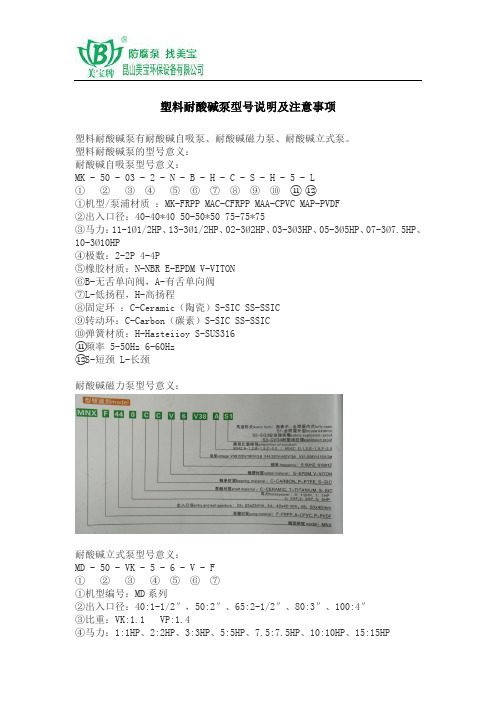
塑料耐酸碱泵型号说明及注意事项塑料耐酸碱泵有耐酸碱自吸泵、耐酸碱磁力泵、耐酸碱立式泵。
塑料耐酸碱泵的型号意义:耐酸碱自吸泵型号意义:MK - 50 - 03 - 2 - N - B - H - C - S - H - 5 - L① ② ③ ④⑤⑥ ⑦ ⑧ ⑨ ⑩⑪⑫①机型/泵浦材质:MK-FRPP MAC-CFRPP MAA-CPVC MAP-PVDF②出入口径:40-40*40 50-50*50 75-75*75③马力:11-1Ø1/2HP、13-3Ø1/2HP、02-3Ø2HP、03-3Ø3HP、05-3Ø5HP、07-3Ø7.5HP、10-3Ø10HP④极数:2-2P 4-4P⑤橡胶材质:N-NBR E-EPDM V-VITON⑥B-无舌单向阀,A-有舌单向阀⑦L-低扬程,H-高扬程⑧固定环:C-Ceramic(陶瓷)S-SIC SS-SSIC⑨转动环:C-Carbon(碳素)S-SIC SS-SSIC⑩弹簧材质:H-Hasteiioy S-SUS316⑪频率 5-50Hz 6-60Hz⑫S-短颈 L-长颈耐酸碱磁力泵型号意义:耐酸碱立式泵型号意义:MD - 50 - VK - 5 - 6 - V - F①②③④⑤⑥⑦①机型编号:MD系列②出入口径:40:1-1/2″,50:2″、65:2-1/2″、80:3″、100:4″③比重:VK:1.1 VP:1.4④马力:1:1HP、2:2HP、3:3HP、5:5HP、7.5:7.5HP、10:10HP、15:15HP⑤频率:5:50HZ,6:60HZ⑥橡胶材质:N-NBR,E-EPDM,V-VITON⑦泵浦材质:F-FRPP,C-CFRPP,A-CPVC,P-PVDF塑料耐酸碱泵现场安装时需要注意的问题:1、安装泵浦时应选择坚固之水平面,保持机身垂直并加以固定。
2、尽量避免将机器装设于户外。
潜水排污泵使用说明书
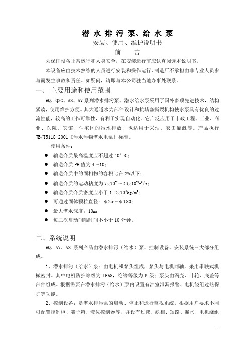
潜水排污泵、给水泵安装、使用、维护说明书前言为保证设备正常运行和人身安全,在安装运行前应认真阅读本说明书。
本设备应由技术熟练的人员进行安装和操作运行,制造厂不承担由非专业人员参与而发生事故和责任。
如疑问,请即与本公司驻当地办事处联系。
一、主要用途和使用范围WQ、QXG、AS、AV系列潜水排污泵、潜水给水泵采用了国外多项先进技术,结构紧凑,使用维护方便。
其大通道水力部件设计和抗堵塞撕裂机构使水泵具有优良的过流性能,较高的工作可靠性,有利于实现自动化。
它广泛应用于市政工程、工业、商业、医院、宾馆、住宅区的污水排放,也适用于采油、农田灌溉等。
产品执行JB/T5118-2001《污水污物潜水电泵》标准。
使用条件:●输送介质最高温度应不超过40°C;●输送介质PH值为4~10;●输送介质中的固相物的容积比在2%以下;●输送介质的运动粘度为7╳10-7~23╳10-6m2/s;●输送介质介质密度应小于1.2╳103kg/m3;●可通过固体颗粒直径:φ25~φ180;●最大潜水深度:10m;●每二次启动间隔时间不小于10分钟。
二、系统说明WQ、AV、AS系列产品由潜水排污(给水)泵、控制设备、安装系统三大部分组成。
1、潜水排污(给水)泵:由电机和泵头组成,泵头与电机同轴,采用串联式机械密封。
其中电机防护等级为IP68,绝缘等级为F级;泵头由涡壳、叶轮、底盖等部件组成。
根据需要在潜水排污(给水)泵内设置有油室泄漏报警、电机绕组过热保护等功能。
2、控制设备:是潜水排污泵的启动、停止和运行监视系统。
根据用户要求不同可配置控制柜、端子箱、液位控制器等,并设有过载、缺相、短路、漏水、电机绕组超温等保护功能。
详见控制设备的随机文件。
3、安装系统:根据工况条件不同,安装方式有固定湿式安装、固定干式安装、移动式安装。
三、特点●独特的电缆密封设计-水密电缆,排除了电缆进水的隐患;●完美的电机冷却设计-水套冷却系统,通过高低压水管实行自流循环冷却(中型泵);●转子和叶轮进行动平衡检测,确保运行平稳。
GN.N.NB型凝结水泵说明书
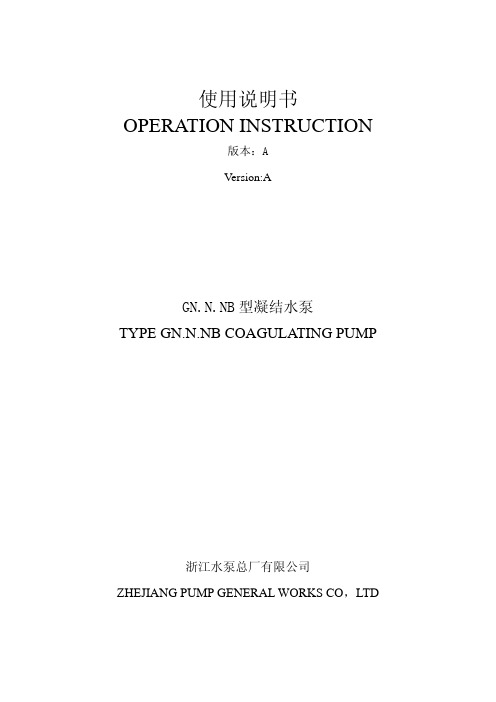
使用说明书 OPERATION INSTRUCTION版本:AVersion:AGN.N.NB型凝结水泵TYPE GN.N.NB COAGULATING PUMP浙江水泵总厂有限公司ZHEJIANG PUMP GENERAL WORKS CO,LTDTYPE GN.N.NB COAGULATING PUMPⅠ、GENERAL DESCRIPTION1、Application and characteristicsType GN、N and NB coagulating pumps have a characteristic of which NPSH’s performance are finer than those of ordinary pumps. It is a suitable corollary equipment for the steam turbogenerators to pump over the condensed water out of the condenser in metallurgical plants, power plants, refineries, chemical and petrochemical plants, low-temperature projects and pump over the liquid from the high-vacuum containers. It is mainly used for the occasions where the cavitation demands high in the process flow in power plants, metallurgical plants, refineries, petrochemical plants, low-temperature projects, pipelines and offshore industries and it can be used in else place where the agent is similar to the condensate water.2、Operation range℃℃The temperature of delivered liquid is below 80(The temperature can be below 150 if a cooling device is fixed in cooling chamber). The head is from 22 meters to 320 meters. The capacity is from 2m3/h to 250 m3/h.3、Type instructionsFor example:GN3/12、3N6×2 and 4N6AMean:3------Suction pipe diameter(inch)N------Condensate pump GN------High suction head condensate pump12------Capacity at design point(m3/h)6------Single-stage head devided by 10 at design point ×2------Stage numbers A------Impeller has been cut first timeFor example:100NB-45 、GN85-80×3Mean:100------Suction diameter(millimeter) GN------High suction condensate pump NB------Condensate pump 85------Head at design point45------Head at design point 80------Single-stage head at design pointⅡ、MECHANISM INSTRUCTION1、Type3N6、4N6、6N6、NB series condensate pumps are single-stage overhung centrifugal pump (construction shown in drawing 1). The suction of the pumps is horizontally and the discharge is vertically upward. The main parts of the pump include pump casing、impeller、pump cover、pump shaft and hang frame. Tow DAN LIE radial ball bearing are assembled in the hang frame to support the pump rotating components and bear the axial force and the radial force of the pump. Lubricating oil lubricates the bearing. Packing to prevent air coming or water leakage seals the shaft seal of the pump. The renewable shaft sleeve is assembled on the shaft seal of the pump to protect the pump shaft, and the O-ring is assembled between the shaft sleeve and the pump shaft to prevent air coming or water leakage in the clearance. The motor directly through the flexible coupling started the pump. The pump rotates in counter clockwise direction, as viewed from the motor side. (Type 200NB-80 rotates in clockwise)2、Type GN、3N6×2、4N5×2、4N6×2 condensate pumps are single-suctionmulti-stages overhung centrifugal pump ( drawing 2、drawing 3). The suction of the pumps is horizontally and the discharge is vertically upward. The main parts of the type GN pump include pump cover、impeller、diffuser、stage casing、pump casing、pump shaft and hang frame. The main parts of the type 3N6×2、4N5×2、4N6×2 pump include pump cover、impeller、diffuser、pump casing、pump shaft and hang frame. The pump rotor was formed with impeller and impeller spacer sleeve assembled on the shaft. Tow DAN LIE radial ball bearing are assembled in the hang frame to support the pump rotating components and bear the axial force and the radial force of the pump. Lubricating oil lubricates the bearing. Packing to prevent air coming or water leakage seals the shaft seal of the pump. The renewable shaft sleeve is assembled on the shaft seal of the pump to protect the pump shaft, and the O-ring is assembled between the shaft sleeve and the pump shaft to prevent air coming or water leakage in the clearance.The motor drives the pump directly through the flexible coupling, The pump rotates in counter clockwise direction, as viewed from the motor side. (The GN80-22 and GN150-90 rotates in clockwise).The material of the main part of the pump:pump casing、pump cover、intake section、middle section、and discharge section: cast iron and cast steel.Inducer、impeller、guide vane、sealing ring and shaft sleeve: cast iron, cast steed, stainless steel and copper alloy.pump shaft: fine carbon steelNote:The factory can supply other materials according to the request of the user.Ⅲ、ASSEMBLE AND DISASSEMBLEType GN、N and NB pump are assembled and disassembled according to the following regulations:1、Supporting Parts℃Fit the bearing which is beaten to about 100 by the oil on the pump shaft , then fit them in hang frame body. The axial location is exactly with ahead roller bearing, the axial position-moving for the shaft is from 0.1mm to 0.15mm.2、Working Partsa.Fit the pump casing and pump cover in hang frame, check that the end surface pulsation don’t exceed 0.15mm. The paper gasket is well set on the sealing surface.b.Assemble impeller: Assemble the shaft sleeve carefully not to injure 0-ring, fix the impeller on the shaft tightly with the impeller nut and check the ring pulsation not exceeds 0.08mm. The impeller rotates in clockwise direction as viewed from the suction direction. (The GN80-22、GN150-90、200NB-80 rotate in counter clockwise).3、Assemble the packingCut the oil-impregnated graphite asbestos rope according to required length of shaft diameter. The inclination of cutting port is about 45°in order to make the joint straight and closely when the rope is enclosed become ring. The joint miss about 120°angle each other when the packing is fitted in the packing box. The packing gland should be pressed tightly. It is suitable that the leakage is about 20~30 drips per minute when the pump is operating.The pump’s disassemble should use the installation of pump itself, every fitting surface should be protected strictly in order to prevent damage.Ⅳ、OUTLINE DIMENSIONS AND INSTALLATION1.Installation outline drawing2.InstallationA.Preparation before installation:(1) Check the pump and the motor so that they aren’t is damaged and there aren’t objects in the pump.(2) Prepare tools and the hoisting machine.(3) Check the base of the pump according to the drawing.B.Procedure of installation(1) Clean the oily and dirty from the pedestal, place the pedestal on the foundation screw that have been embedded before, there are a pair of wedges under the pedestal.(2) Use level gauge to check the level degree of the pump’s pedestal.(3) Fill up the hole eye of the foundation screw and the internal cavity of the pump pedestal with the cement grout.(4) After the cement grout has been hardened completely, tighten the nut of the foundation screw.(5) Cleanse the supporting plane of the pedestal carefully, recheck the level of the pedestal and cleanse the foundation plane of the pump and the motor, then put the pump and the motor on the pedestal.(6) Check the level degree of the pump shaft and the motor shaft according to the following drawing.(7) Check the same center degree between the pump shaft and the motor shaft after the suction piping has been joined to the discharge piping.(8) Join the suction pipe to the top of the condensate with the air-drain pipe.(9) The water-sealing water can be filled in from the by-pass installed behind the check valve door of discharge piping.C .The vacuum equilibrium pipelineD .pump.(2) Suction piping should be sealed completely, the shape of the suction piping should prevent forming air pocket when the water-pressure test is carrying on at the pressure of 0.2Mpa.(3) The water-flow speed in suction piping should equal to 2m/s or less than 2m/s. The suction piping don’t be too long, but should avoid marking a turn rapidly. The flow control valve is not allowed to be installed on the suction pipeline, only a vacuum pump is allowed with it in full open state.E. The high calculation of installation of pump:The condensation pump is generally used to aspirate the condensation water usefulness in the closed container, and should be designed for the flowing backward device. It pours Into highly to calculate. Otherwise possibly causing pump vapor to lose owing to pours into inadequately, and influencing the normal work of pump, the damage pump causes the accident when serious.It pours into the calculation formula for:[]c c v c k h g p g p NPSH hg +++−≥ρρIn the type:[NPSH] – Net positive suction head parameter of pump (m)h c --- Absorbing into the waterpower of pipe route loses (m)k c --- The safe parameter of net positive suction head of pump, and usually take 0.3 - 0.5m--- Absolute pressure flood peak (m) of liquid face in the container ρg p c--- Lashes the vaporization sent under liquid temperature pressure flood peak (m) ρg pvⅤ、START AND STOP1、Preparation before start(1) The No. 20~30 machine oil was filled into hang frame body from the oil hole on top of the hang frame until the oil surface gets to the middle part of the oil meter.(2) The pump won’t operate under the condition that there is no water in the pump, fill the pump with water fully before starting pump, water-sealing must be given and the pressure of water-sealing water should be greater than the pressure of the suction about 0.15Mpa. When the condensate pump is used as a stand-by pump, the valves on degassing pipe and air discharging pipe should be maintained open so as to let the air in pump chamber release, then connect the outside sealed water or wash the pipe by the machine in sealing condition and then fill the pump chamber with water for emergency starting.(3) Determine the rotate direction of the motor. The pump rotates in counter clockwise as viewed from the motor side. (Type GN80-22、GN150-90、200NB-80 rotate in clockwise ). After joining the motor to the pump finish, check the pump if it is turned lighthearted and uniform.(4) The gate valve of discharge piping should be turned off after the pump is started.2、Start(1) When the pump operated under normal revolutions, open the discharge piping gate valve a little, and check the working situation of all gauge and packing. The working time for the pump doesn’t allow too long under the condition that the discharge gate valves was closed down.(2) Check the temperature of the bearing and the packing, if the temperature of them is too heat, stop the pump immediately, the water will be leakage from the packing regularly.(3) If the pump operated very normally and the discharge gate valve has been opened until the required working condition is produced, the pump’s start will be finished.3、Stop(1) Gradually close down the gate valve on the discharge piping, then cut off the circuit of the motor.(2) The pump, which is used to reserve operation as stopping, must be putted on the watersealing.(3) If the pump will not be used for along period of time, it should be disassembled, smeared over oil and packed then properly preserve the pump.Ⅵ、OPERATION AND MAINTENANCE1、As the pump is being operated, take care to observe the pressure gauge, vacuum gauge, the temperature of the bearing, the situation of water for the packing, oil position of the bearing and that the vibration and abnormal sound.2、The maximum temperature of the bearing should be not higher than 75, and the risen℃℃temperature of the bearing don’t exceed 50.3、Change the lubricating oil after the pump has been operated for 100 hours within first working month, Later replace new oil after the pump has been operated for 2400 hours every time.4、If any abnormal things (such as strenuous vibration and noise) occur when the pump is under operation, immediately find reasons and eliminate them, then take notes the result of observing and handling.5、The trouble happened possibly and the solving methods:No. Trouble Reasons Solving Methods1 The pumpcan’tdeliverwater1. The rotating direction for thepump is not right.2. The pouring pressure is notenough, the suction pipe or metervalve is leakage of air.3. There is some air pocket in thepump chamber.1.The pump shaft rotates in counterclockwise direction as viewed fromthe motor side, if the direction isn’tright, exchange the joint of wire.2. Adjust the discharge gate valve toreduce the capacity or increase thepouring pressure, tighten up orchoking up the steam-leakageplace.3. Open the pipe plug on top of thepump casing to drain steam.2Thecapacity orhead isreducedwhen thepump isoperating1. The temperature of the suction istoo high.2. The abrasion interval of thesealing ring is too big.3.The working impeller is damagedor stopped up.4.The measuring meter isn’tcorrect.5.There are some air pocket inpump chamber.1.The pump is only used that thetemperature is below 80.℃2.Replace the sealing ring againnecessary.3.Clean the interior of the workingimpeller.4.Check the meter.5.Open the screwed plug on top of thepump casing to drain air.3 The motoris overload1.The pump capacity exceedsstipulate capacity.2.The packing is too tighter.3.The interior of the pump wasentangled by cotton yarn.1.Check the flow gauge and adjustthe capacity with gate valve.2.Injust the packing gland.3.Disassemble the pump and cleanthe internal impurity.4Thebearing istoo heat1. The ring bush was abrasionbecause the pump shaft has beenbend.2.The lubricating oil of the bearingis not enough.3.The center between the pumpshaft and the motor shaft isn’tright.4.The balance water return pipeflows not well or the rear rearsealing ring gap too large andaxial force too high.1. Check the ring bush and thestraightness of the shaft.2. Pour in oil.3. Check the coupling to aim atcenter.4.Keep the balance water return pipewell flow adjust the gap and setaxial force balance.5The pumpoccurvibration1.The center between the pumpshaft and the motor shaft isn’tright.2.The rotor isn’t balance.3.The foundation bolt and the studbolt on the pump frame are notright.4.Covitation occurs on pump.1.Check the coupling to aim at center.2.Check the rotor.3.Fix all bolts tightly4.Try to find the cause and handle it. 6、If any special things don’t occur, the overhaul of the pump will be carried on together withthe general overhaul of the machirevy.。
杭氧操作说明书

三、分子筛吸附自动控制系统
分子筛吸附器是二组(只)卧装的园柱形容器,每只容器中均充 有分子筛吸附剂。两组(只)分子筛吸附器 01R201A、01R201B 是交 替工作的,即当一组(只)吸附器运行在吸附工作状态时,另一组(只) 则运行在再生状态。处在吸附工作状态的吸附器,通过经过冷却的原 料空气,当空气通过分子筛时,空气中的水份、CO2 和碳氢化合物被分 子筛吸附,使空气得到净化。经过一段时间的吸附,分子筛就得进行 再生,使分子筛吸附剂析出水份及 CO2 等,经过再生的吸附器又可以投 入吸附工作,二组(只)吸附器是交替地工作的。 1. 分子筛吸附器再生过程
第十五步 2.6 准备充压:打开 KV01219,确认 KV01219 开,关闭 KV01212、KV01214,确认 KV01212 关
第十六步 2.7 充 压:打开 KV01207,计时 22 分,PDIS01201 达 到给定值及计时到,关闭 KV01207
第十七步 2.8 准备交换:打开 KV01204,确认 KV01204 开 第十八步 2.9 交 换:打开 KV01202,确认 KV01202 开,记时 3
初 始 化 : KV01201 、 KV01202 、 KV01203 、 KV01204 、 KV01217、KV01219 开,其余阀门均关闭
第一步 1.1 准备卸压:关闭 KV01201、KV01203,确认 KV01201、 KV01203 关
第二步 1.2 卸 压:打开 KV01205,计时 8 分,PIS01201 达到给定 值及计时到关闭 KV01205
中原大化 52000Nm3/h 成套空分设备 仪控系统说明书 (KOD52.10000SM)
二零零六年二月
目
录
注碱操作规程与注碱泵保养规程

危害评价和控制报告酸化注碱安全操作规程、应急处理办法和环保一、施工前检查:1)、外观检查(1)检查注碱泵和加热罐的外观是否完好。
(2)压力表、安全阀门、截止阀是否被碰坏或碰掉。
(3)电缆线有无损伤,接头处有无松动。
(4)紧固松动螺栓、螺帽等。
2)、接好电源,连接好流程,试运转:(1)将一定量的水加到加热罐中,液位应超过加热盘管,即液位计30cm处;检查出水口是否出水畅通,碟阀是否漏水。
(2)检查注碱泵齿轮油的油位是否合理,油位应在液位计1/2处。
(3)连接高低压流程,检查管线有无堵塞,如有,则及时更换;(连接前注意检查快速接头处是否有密封垫。
)(4)连接好电源(电源要求:注碱泵电压380V,电流5A,加热罐电压为380V,电流为68A。
),检查设备电源开关的良好性;(5)把流程倒通后,试运转(注意:正反转,如果反转,则调整电源线接头;判断正反转,电机上有箭头标示。
);(6)将加热罐电源开关打开,检查温度表、水位限制器和自动加热系统的灵敏性;(正常工作过程中温度表的读数应19℃-35℃之间。
)(5)试运转过程中,注碱泵上水、出水如不正常,则检查上水流程和出水流程,即将上水或出水流程拆掉,检查上水排水球、球座和导向架的完好性,如有损坏应及时更换。
(6)流程完好后;检查压力表是否正常,流量表指针是否准确;各阀门是否完好;流程有无刺漏;单流阀是否完好;泻压阀是否符合注碱泵的要求;盘根处有无漏水或漏油现象;如有问题,则应及时修理或更换。
二、施工操作:检查设备完好后,准备注碱作业。
(1)碱液提前半小时配置好,并搅拌均匀,根据作业需求选择自动(注碱过程中有停顿)或手动(注碱一直在进行)开关;碱液温度保持19-35℃,浓度最好在10~16%;(2)加碱过程中,一定要谨慎小心,不要让杂物落入罐中,防止流程堵塞。
(3)连接泵到采油树流程。
(注意:根据现场需要进行连接,单流阀必须水平放置,保证单流阀正常工作,以保护注碱流程的安全性。
碱液输送泵说明书书—浙江天德泵业有限公司
位号
泵名称 CFP锅炉柴油供油泵
燃油锅炉柴油供油泵 碱液输送泵 柴油卸油泵 污油回收泵
3.润滑油用量:32# 透平油
位号
泵名称 CFP锅炉柴油供油泵 燃油锅炉柴油供油泵
碱液输送泵
柴油卸油泵 污油回收泵
泵型号 GSB-F-8/250 GSB-Q-18/350
TL6-60 TH65-40-200A ZX32-25-160
程
)
扬程
(Ⅲ)
轴功率 泵效率
((kkⅥⅦ)
(‖)
10·0069·8703。880·68750。00592988°00。0066.55 3·5470°00
21·0169·6q04·110·68500°00572987。61°0066°44 3°7556°57
31·7269·3204·260·68370。00562987°61°6865°97 3°89410·4q
能 性 泵
泵′性能数据报告
报告编编ˉ号号::cc112200118822
|泵泵型 型号号|TL6TˉL66=600
共共44页页第第11页页
|试试验验日日期期|20210212ˉˉ0099-ˉ2828水 |水温温|2288.0.(0℃()℃)|流流量量计计量量程程|32032.01.177
制造单位 屯电机功率竿 额定流量
Kg/m3
1320
4 入口条件下的粘度
CP
8.8
5 入口条件下的汽化压力 MPa.A
6 入口压力
MPa.A
7 出口压力
MPa.A
0.6
8 压差
MPa.G
9 扬程
m
60
10 流量
m3/h
最小
正常
- 1、下载文档前请自行甄别文档内容的完整性,平台不提供额外的编辑、内容补充、找答案等附加服务。
- 2、"仅部分预览"的文档,不可在线预览部分如存在完整性等问题,可反馈申请退款(可完整预览的文档不适用该条件!)。
- 3、如文档侵犯您的权益,请联系客服反馈,我们会尽快为您处理(人工客服工作时间:9:00-18:30)。
本文部分内容来自网络整理,本司不为其真实性负责,如有异议或侵权请及时联系,本司将立即删除!== 本文为word格式,下载后可方便编辑和修改! ==杭碱泵说明书篇一:碱液泵说明书化学品安全技术说明书化学品名称:氢氧化钠第一部分:化学品名称化学品中文名称:液体氢氧化钠化学品英文名称: sodiun hydroxide 中文名称2:烧碱英文名称2: caustic soda生产企业中文名称:生产企业英文名称:企业地址:邮编:传真号码:企业应急电话:电子邮件:技术说明书编码:生效日期:201X.8.22国家应急电话:120,119,110第二部分:成分/组成信息有害物成分:氢氧化钠分子式: naoh 分子量: 40.01含量:液碱≥29% cas no. : 1310-73-2 第三部分:危险性概述危险性类别:第8.2类碱性腐蚀品侵入途径:由呼吸道、消化道、皮肤侵入健康危害:本品有强烈刺激和腐蚀性。
粉尘刺激眼和呼吸道,腐蚀鼻中隔;皮肤和眼直接接触可引起灼伤;误服可造成消化道灼伤,粘膜糜烂、出血和休克。
环境危害:对水体可造成污染。
燃爆危险:本品不燃,具强腐蚀性、强刺激性,可致人体灼伤。
第四部分:急救措施皮肤接触:立即脱去污染的衣着,用大量流动清水冲洗至少15分钟。
就医。
眼睛接触:立即提起眼睑,用大量流动清水或生理盐水彻底冲洗至少15分钟。
就医。
吸入:迅速脱离现场至空气新鲜处。
保持呼吸道通畅。
如呼吸困难,给输氧。
如呼吸停止,立即进行人工呼吸。
就医。
食入:用水漱口,给饮牛奶或蛋清。
就医。
第五部分:消防措施危险特性:与酸发生中和反应并放热。
遇潮时对铝、锌和锡有腐蚀性,并放出易燃易爆的氢气。
本品不会燃烧, 遇水和水蒸气大量放热, 形成腐蚀性溶液。
具有强腐蚀性。
有害燃烧产物:可能产生有害的毒性烟雾。
灭火方法:用水、砂土扑救,但须防止物品遇水产生飞溅,造成灼伤。
灭火注意事项及措施:消防员个体防护穿防酸碱工作服、戴耐酸碱手套。
第六部分:泄漏应急处理应急处理:隔离泄漏污染区,限制出入。
建议应急处理人员戴防尘面具(全面罩),穿防酸碱工作服。
不要直接接触泄漏物。
小量泄漏:避免扬尘,用洁净的铲子收集于干燥、洁净、有盖的容器中。
也可以用大量水冲洗,洗水稀释后放入废水系统。
大量泄漏:收集回收或运至废物处理场所处置。
第七部分:操作处置与储存操作注意事项:密闭操作。
操作人员必须经过专门培训,严格遵守操作规程。
建议操作人员佩戴头罩型电动送风过滤式防尘呼吸器,穿橡胶耐酸碱服,戴橡胶耐酸碱手套。
远离易燃、可燃物。
避免产生粉尘。
避免与酸类接触。
搬运时要轻装轻卸,防止包装及容器损坏。
配备泄漏应急处理设备。
倒空的容器可能残留有害物。
稀释或制备溶液时,应把碱加入水中,避免沸腾和飞溅。
第八部分:接触控制/个体防护职业接触限值中国mac(mg/m3): 0.5前苏联mac(mg/m3): 0.5tlvtn: osha 2mg/m3tlvwn:acgih 2mg/m3监测方法:酸碱滴定法;火焰光度法工程控制:密闭操作。
提供安全淋浴和洗眼设备。
呼吸系统防护:可能接触其粉尘时,必须佩戴头罩型电动送风过滤式防尘呼吸器。
必要时,佩戴空气呼吸器。
眼睛防护:呼吸系统防护中已作防护。
身体防护:穿橡胶耐酸碱服。
手防护:戴橡胶耐酸碱手套。
其他防护:工作场所禁止吸烟、进食和饮水,饭前要洗手。
工作完毕,淋浴更衣。
注意个人清洁卫生。
第九部分:理化特性外观与性状:白色不透明固体,易潮解。
熔点(℃): 318.4沸点(℃): 1390相对密度(水=1): 1.31相对蒸气密度(空气=1):无资料饱和蒸气压(kpa):0.13(739℃) 燃烧热(kj/mol):无意义临界温度(℃):无意义临界压力(mpa):无意义辛醇/水分配系数的对数值:无资料闪点(℃):无意义引燃温度(℃):无意义爆炸上限%(v/v):无意义爆炸下限%(v/v):无意义溶解性:易溶于水、乙醇、甘油,不溶于丙酮。
溶解时产生大量的热,这些溶液与酸混合时也产生大量的热。
主要用途:用于肥皂工业、石油精炼、造纸、人造丝、染色、制革、医药、有机合成等。
其它理化性质:从空气中迅速吸收水分的同时,也迅速吸收二氧化碳。
第十部分:稳定性和反应活性稳定性:稳定禁配物:强酸、易燃或可燃物、二氧化碳、过氧化物、水。
避免接触的条件:潮湿空气。
聚合危害:无意义分解产物:无意义第十一部分:毒理学资料急性毒性:ld50:小鼠腹腔内ld50:40mg/kg.兔经口ld50:500mg/kg。
lc50:无资料急性中毒:吸入氢氧化钠的汽雾时,可引起化学性上的呼吸道炎。
皮肤接触可引起灼伤。
口服后,口腔、食管、胃部灼烧痛,腹绞痛、呕吐血性胃内容物,血性腹泻。
有时发生声哑、吞咽困难、休克、消化道穿孔。
后期可发生胃肠道狭窄。
氢氧化钠溅入眼内,可发生结膜炎、结膜水肿、结膜和角膜坏死。
严重者可致失明。
亚急性和慢性毒性:无资料刺激性:家兔经眼:1%重度刺激。
家兔经皮:50mg/24 小时,重度刺激。
致敏性:无资料致突变性:无资料致畸性:无资料致癌性:无资料其他:无资料第十二部分:生态学资料生态毒理毒性:无资料生物降解性:无资料非生物降解性:无意义生物富集或生物积累性:无资料其它有害作用:由于呈碱性,对水体可造成污染,对植物和水生生物应给予特别注意。
第十三部分:废弃处置废弃物性质:危险废物废弃处置方法:处置前应参阅国家和地方有关法规。
中和、稀释后,排入废水系统。
废弃注意事项:穿防护用品,加酸中和第十四部分:运输信息危险货物编号: 8201Xun编号: 1824包装标志:腐蚀品包装类别: ii类包装包装方法:液体氢氧化钠通常采用普通碳素钢作的槽罐车、船舶散装。
运输注意事项:铁路运输时,钢桶包装的可用敞车运输。
起运时包装要完整,装载应稳妥。
运输过程中要确保容器不泄漏、不倒塌、不坠落、不损坏。
严禁与易燃物或可燃物、酸类、食用化学品等混装混运。
运输时运输车辆应配备泄漏应急处理设备。
第十五部分:法规信息法规信息:化学危险物品安全管理条例 (201X年3月15日实施,国务院发布),化学品安全技术说明书编写规定(gb16483-201X),化学品安全标签编写规定(gb15258-1999),工作场所安全使用化学品规定 ([1996]劳部发423号)等法规,针对化学危险品的安全使用、生产、储存、运输、装卸等方面均作了相应规定;常用危险化学品的分类及标志 (gb 13690-92)将该物质划为第8.2类碱性腐蚀品。
其它法规:隔膜法烧碱生产安全技术规定 (hga001-83);水银法烧碱生产安全技术规定 (hga002-83);离子膜法烧碱安全生产技术规定(hab004-201X)。
第十六部分其他参考文献:1.周国泰,化学危险品安全技术全书,化学工业出版社,19972.国家环保局有毒化学品管理办公室、北京化工研究院合编,化学品毒性法规环境数据手册,中国环境科学出版社.19923.常用化学危险物品安全手册4.危险化学品安全管理培训教程,青岛市新闻出版局,201X填表时间:填表部门:修改说明:其他信息:无篇二:流程泵使用说明书(中文) 目录1.概述?????????????????????????⑵2.泵的说明???????????????????????⑵3.型号说明???????????????????????⑵4.泵的安装???????????????????????⑶5.管路及其辅助设备???????????????????⑷6.使用?????????????????????????⑹7.维护保养???????????????????????⑺8.检修?????????????????????????⑻9.故障原因及消除方法??????????????????⑾1一、概述1、产品特点:gz型离心式流程泵,是根据api610规范设计的,该流程泵具有可靠性高,使用寿命长,通用化程度高的特点,尤其是效率高更为突出。
2、主要用途及适用范围该型泵适合输送清洁或稍有污染的液体低温或高温的液体,中型或有腐蚀性的液体,有毒、易燃易爆介质主要用于:? 炼油厂、石油化工工业、煤加工工业和低温工程 ? 化工工业,造纸、纸浆业,制糖业和普通流程工业 ? 供水厂,海水淡化厂 ? 供暖和空调调节系统 ? 发电厂 ?环境保护工程 ?船舶及海上工业等 3.型号说明材质代号冷却方案冲洗方案密封方案叶轮代号(a、b、c、d)叶轮名义直径(200mm)泵出口直径(25mm)结构类型石油化工工艺流程泵3.1结构类型 23.2过流部件材质代号4、安全本使用说明书是对安装、使用和维修的重要论述。
因此,对于装配人员以及所有的负责者在装配和开车前必须全部阅读本说明书,本说明书也适用于以后的安装,维修。
泵的使用安全仅在规定的使用场合(见数据单)下得到保证。
如果辅助装置(如:冷却、最小流量调节装置)发生故障能导致泵内有不允许的压力增加,则装置内必须装有适当的安全装置。
对于输送过热或过冷介质的泵,其泵的有关零件必须采取防止接触的装置。
如果在泵停车以后可能产生有害的回流,则必须安装回流预防装置。
在泵启动以前必须安装防护装置(联轴器罩)。
泄漏液体的排放危及周围环境,因此必须合乎环境保护法。
必须经常检查泵体,密封环和叶轮的腐蚀,磨损情况,并保证及时更换已腐蚀或已磨损的零件。
装配和拆卸时注意安全,在安装时要保证泵的平稳,防止零件脱落,保证泵的可靠性。
连接法兰,连接螺孔,以及其它敞开部位在运输和存放期间必须保持封闭。
注意:对于泵单机或整体的吊运不允许使用泵部分或电机上的起吊环,起吊环仅供给装配或拆卸松开的单件吊运。
泵单机的吊运应将绳索绕在泵体法兰或轴承支架上,整机吊运应使用底座地脚螺栓孔。
二、结构特征 1、结构特征gz系列泵属卧式、单吸离心流程泵。
该系列泵温度范围为-80℃~+450℃,最高使用压 3力达 2.5mpa,当使用温度高于175℃时,泵采用水平中心支撑,以把热膨胀冷缩产生的变形及位移降低到最低限度。
gz型流程泵,可保证流程工业要求的维修条件,轴承、轴封和叶轮为一转子组件可进行迅速的拆卸或装配,大大缩短了停车时间。
叶轮可用闭式、半开式、开式三种。
可输送清洁,含颗粒,含少量气体介质,也可输送高温、低温、强腐蚀介质。
叶轮设有平衡孔,平衡轴向力。
轴封腔(填料函)和泵盖是铸成一体的,它可以装填料密封及单端面和双端面机械密封,轴封腔外面铸有可供选择的水冷腔夹套,水冷夹套的配备必须是特别提出要求或者当输送介质为水的温度超过66℃,以及碳氢化合物温度超过150℃时用。
当输送介质需要保温时,在其夹套内还可以通入低压蒸气或其它保温液体。
液体进入接头g1/2”,一般在泵盖下方,液体出口接头g1/2”在泵盖上方。