Huawei_LiteOS在STM32系列处理器上的移植-Huawei_LiteOS_workshop
华为LiteOS操作系统基础知识入门与内核移植

华为LiteOS操作系统基础知识入门与内核移植LiteOS操作系统是华为在2015年发布的一个轻量级的面向物联网的操作系统,同时也是华为物联网1+2+1物联网解决方案的组成部分,此操作系统具备零配置,自发现,自组网的特点,让LiteOS的终端物联能够自动接入支持的网络,使得硬件开发变得更加简单,对于开发者来说也有很强的便利性。
本文章将对LiteOS操作系统基本结构及应用场景进行简单介绍,最后介绍如何移植LiteOS内核。
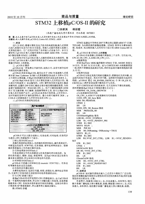
1. LiteOS内核结构简介HUWEI LiteOS内核结构如图所示,其内核主体可分为硬件抽象层,基础内核和扩展内核,其中基础内核中的极小内核是LiteOS操作系统能够裁剪的最小单位,包括任务管理、内存管理、中断管理、异常管理和系统时钟等功能,可裁剪部分则包括信号量、互斥锁、队列管理、事件管理、软件定时器等。
而除了基础内核,Huawei LiteOS 还提供了扩展内核,包括C++支持、动态加载、低功耗以及维测模块。
低功耗通过支持Tickless机制、run-stop休眠唤醒,可以大大降低系统功耗。
维测部分包含了获取CPU占用率、支持串口执行Shell命令等功能。
除此之外,LiteOS也具有云端协同的能力,集成了全套IOT 协议,LwM2M、CoAP、mbedtls、LwIP等。
2. 应用场景举例基于其可裁剪型强,对MCU环境适配性强等优势,LiteOS在多个领域都得到了广泛应用在家居领域,华为推出了华为HiLink智能家居解决方案,该方案结构图如图所示从图中看,该方案主要由HiLink SDK,智能设备,HiLink智能路由,云平台,手机APP及互联协议组成;整体的运作流程是,生态伙伴产品硬件内部已经安装了HiLink SDK及LiteOS内核,基于内核含有的通信协议(Zigbee,NBioT)等,与HiLink智能路由产生联系,生态伙伴产品通过智能路由组网与APP和家庭云互传信息,以达到智能家居的效果。
STM32上移植μC/OS-Ⅱ的研究
M RS R0 PRI A SK , M CPSI D I
S M3 是意法 半导体 在 2 0 年推 出的 以最新 A O . T 2 07 M R V7C R T X. E ME 为 内核 的高 性 能微处 理 器 。S M3 T 2系列 专 为要 求 高性 能 、 成本 、 功耗 的嵌入 式 应用专 门设计 的 A M o e . 低 低 R C r xM3内 t 核。 五 、 C O . 在 S M3 上 的移植 p / SI I T 2 p / — 在 处理器 上 的移 植只 需修 改三 个文 件 。它们是 O C OSI I S CP . 、 U H OS CP A. M、 — U— C。 U AS OS CP C. a数据 类型 ) 经查 R a i el e MDK编 译器 和 S M3 V w T 2手册 , H R S O T类 型为 1 6位长 ,而 I NT为 3 2位长 度 。这 与 C T X M3内核数 据类 型 OR E . 致; 因而 不需 要更 改此 部分 代码 。 同时 状态 奇存 器和 堆栈 指针 都
一
、
前 言
进入 2 世 纪 , l 随着计 算机 及 电子技术 的高速 发展 ; 式系 统 嵌入 已深 入到 我们 生活 当 中的 方方 面面 。而 嵌入式 操作 系统 又 是嵌 入 式系 统 的基石 。它广 泛 的应用 到 了各种 嵌入 式 设备 当 中。本 文 主 要研 究 T ̄ / SI嵌入 式操 作系 统 在 以最新 AR 内核 :C r x CO . I M ot — e M3微处 理器 S M3 T 2上 的移 植 。 本文 首先 介绍 Tp / . 嵌 入式 操作 系统 及其 内核 结构 ,随 COSI I 后介 绍 Tp /SI嵌 入 式操 作系 统在 基于 C r xM3内核 的微 处 CO . I ot . e
STM32 系列MCU 不同型号的移植步骤解析
STM32系列MCU不同型号的移植!
第一步
更换启动件:
第二步
修改宏定义:
图1
或者修改stm32f10x.h
具体修改如下:
图2
第三步
修改系统主频率:
文件:system_stm32f10x.c
具体修改如下:
图3
第四步
修改外部晶振源:
文件:stm32f10x.h
其中,Project.bin和Project.axf要和Output选项卡中的Nameof
Executable的名字相同
三、如何使用IAP
1、设置超级终端波特率选择为115200
2、需要下载时将Tamper键按住再按下复位键超级终端打印出帮助信息
3、选择下发文件,协议选择Y_modem,选择下发。
延时修改
使用J-Link调试设置
图7
J-Link不能正常连接目标板
可以尝试一下方法(恢复出厂设置)
具体修改如下:
图4
第五步
定时器需要根据以上修改的系统主频率进行对应的修改。
其他:
修改Flash地址
文件:misc.h
具体修改如下:
图5
与以下配置一致:
IAP设置步骤
一、IAP工程设置
1、修改main中的按键触发键
2、修改下载串口
二、下载工程设置
1、修改程序入口地址
查找NVIC_VectTab_FLASH将其修改为:0x08002000
2、修改options
1)打开Target选项卡在IROM1中将Start和Size分别修改为
0x08002000和0x3E00
2)打开User选项卡在RunUserProgramsBeforeBuild/Rebuild中,勾选
基于STM32单片机的uCOS-II操作系统移植

第6期2020年12月机电元件ELECTROMECHANICALCOMPONENTSVol 40No 6Dec 2020收稿日期:2020-10-20基于STM32单片机的uC/OS-II操作系统移植张中前(贵州航天电器股份有限公司,贵州贵阳,550009) 摘要:网络技术和信息技术的发展,嵌入式系统应用越来越普及,嵌入式设备的应用也越来越多。
uC/OS-II广泛应用于路由器、飞行器及工业控制等。
uC/OS-II操作系统执行效率高,占用存储空间少,具有实时性及可扩展性等优点,在小型嵌入式设备中具有广泛应用。
本文介绍了基于ARMCORTEXM3系列单片机上的uC/OS-II移植,对电子控制组件的设计具有参考作用。
关键词:实时操作系统;uC/OS-II;内存管理;任务管理;STM32;移植Doi:10.3969/j.issn.1000-6133.2020.06.015中图分类号:TN784 文献标识码:A 文章编号:1000-6133(2020)06-0057-051 引言操作系统是裸机的第一层软件,操作系统直接运行在硬件上,上层软件通过提供应用程序接口(API函数),实现对底层硬件的访问,同时,通过操作系统实现对多个上层应用软件(任务)管理,实现对硬件CPU管理、存储管理、I/O接口管理及文件管理,如图1所示。
图1 操作系统功能组成示意图 STM32系列单片机以其优良的价格,大容量的FLASH及RAM存储空间,极易用于较为复杂的控制系统;在STM32单片机上进行uC/OS-II实时操作系统的移植,提高了产品的设计灵活性,实现较为复杂的系统功能;通过将开源的uC/OS-II移植在STM32单片机上,以其较为低廉的硬件成本获得较高的使用性能,具有良好的应用前景。
2 uC/OS-II操作系统2.1 uC/OS-II操作系统的基本特征uC/OS-II是一个完整的、可移植、可固化、可剪裁的基于优先级调度的抢占式实时多任务操作系统;它能够在外界事件或数据产生时,能够接收图2 uC/OS-II文件结构示意图并以足够快的速度响应,其处理的结果又能够在规定的时间内输出,并控制所有实时任务协调、一致运行。
STM32F1系列产品的应用移植到STM32L1系列产品中
March 2012Doc ID 018976 Rev 21/52AN3422Application noteMigration of microcontroller applicationsfrom STM32F1 to STM32L1 series1 IntroductionFor designers of STM32 microcontroller applications, it is important to be able to easily replace one microcontroller type by another one in the same product family. Migrating an application to a different microcontroller is often needed, when product requirements grow, putting extra demands on memory size, or increasing the number of I/Os. On the other hand, cost reduction objectives may force you to switch to smaller components and shrink the PCB area.This application note is written to help you and analyze the steps you need to migrate from an existing STM32F1 devices based design to STM32L1 devices. It groups together all the most important information and lists the vital aspects that you need to address.To migrate your application from STM32F1 series to STM32L1 series, you have to analyze the hardware migration, the peripheral migration and the firmware migration.To benefit fully from the information in this application note, the user should be familiar with the STM32 microcontroller family. Y ou can refer to the following documents that are available from .●The STM32F1 family reference manuals (RM0008 and RM0041), the STM32F1 datasheets, and the STM32F1 Flash programming manuals (PM0075, PM0063 and PM0068).●The STM32L1 family reference manual (RM0038), the STM32L1 datasheets, and the STM32F1 Flash and EEPROM programming manual (PM0062).For an overview of the whole STM32 series and a comparison of the different features of each STM32 product series, please refer to AN3364 Migration and compatibility guidelines for STM32 microcontroller applications .Contents AN3422Contents1Introduction . . . . . . . . . . . . . . . . . . . . . . . . . . . . . . . . . . . . . . . . . . . . . . . . 1 2STM32L1 family overview . . . . . . . . . . . . . . . . . . . . . . . . . . . . . . . . . . . . . 6 3Hardware migration . . . . . . . . . . . . . . . . . . . . . . . . . . . . . . . . . . . . . . . . . . 84Peripheral migration . . . . . . . . . . . . . . . . . . . . . . . . . . . . . . . . . . . . . . . . 124.1STM32 product cross-compatibility . . . . . . . . . . . . . . . . . . . . . . . . . . . . . 124.2System architecture . . . . . . . . . . . . . . . . . . . . . . . . . . . . . . . . . . . . . . . . . 144.3Memory mapping . . . . . . . . . . . . . . . . . . . . . . . . . . . . . . . . . . . . . . . . . . . 144.4RCC . . . . . . . . . . . . . . . . . . . . . . . . . . . . . . . . . . . . . . . . . . . . . . . . . . . . . 174.5DMA . . . . . . . . . . . . . . . . . . . . . . . . . . . . . . . . . . . . . . . . . . . . . . . . . . . . . 244.6Interrupts . . . . . . . . . . . . . . . . . . . . . . . . . . . . . . . . . . . . . . . . . . . . . . . . . 264.7GPIO . . . . . . . . . . . . . . . . . . . . . . . . . . . . . . . . . . . . . . . . . . . . . . . . . . . . 284.8EXTI source selection . . . . . . . . . . . . . . . . . . . . . . . . . . . . . . . . . . . . . . . 304.9FLASH . . . . . . . . . . . . . . . . . . . . . . . . . . . . . . . . . . . . . . . . . . . . . . . . . . . 314.10ADC . . . . . . . . . . . . . . . . . . . . . . . . . . . . . . . . . . . . . . . . . . . . . . . . . . . . . 324.11PWR . . . . . . . . . . . . . . . . . . . . . . . . . . . . . . . . . . . . . . . . . . . . . . . . . . . . . 344.12RTC . . . . . . . . . . . . . . . . . . . . . . . . . . . . . . . . . . . . . . . . . . . . . . . . . . . . . 365Firmware migration using the library . . . . . . . . . . . . . . . . . . . . . . . . . . 375.1Migration steps . . . . . . . . . . . . . . . . . . . . . . . . . . . . . . . . . . . . . . . . . . . . . 375.2RCC . . . . . . . . . . . . . . . . . . . . . . . . . . . . . . . . . . . . . . . . . . . . . . . . . . . . . 375.3FLASH . . . . . . . . . . . . . . . . . . . . . . . . . . . . . . . . . . . . . . . . . . . . . . . . . . . 395.4GPIO . . . . . . . . . . . . . . . . . . . . . . . . . . . . . . . . . . . . . . . . . . . . . . . . . . . . 435.4.1Output mode . . . . . . . . . . . . . . . . . . . . . . . . . . . . . . . . . . . . . . . . . . . . . 435.4.2Input mode . . . . . . . . . . . . . . . . . . . . . . . . . . . . . . . . . . . . . . . . . . . . . . . 435.4.3Analog mode . . . . . . . . . . . . . . . . . . . . . . . . . . . . . . . . . . . . . . . . . . . . . 435.4.4Alternate function mode . . . . . . . . . . . . . . . . . . . . . . . . . . . . . . . . . . . . . 445.5EXTI . . . . . . . . . . . . . . . . . . . . . . . . . . . . . . . . . . . . . . . . . . . . . . . . . . . . . 455.6ADC . . . . . . . . . . . . . . . . . . . . . . . . . . . . . . . . . . . . . . . . . . . . . . . . . . . . . 465.7PWR . . . . . . . . . . . . . . . . . . . . . . . . . . . . . . . . . . . . . . . . . . . . . . . . . . . . . 47 2/52Doc ID 018976 Rev 2AN3422Contents5.8Backup data registers . . . . . . . . . . . . . . . . . . . . . . . . . . . . . . . . . . . . . . . . 49 6Revision history . . . . . . . . . . . . . . . . . . . . . . . . . . . . . . . . . . . . . . . . . . . 50Doc ID 018976 Rev 23/52List of tables AN3422 List of tablesTable 1.STM32L1 peripherals compatibility analysis. . . . . . . . . . . . . . . . . . . . . . . . . . . . . . . . . . . . . 6 Table 2.STM32F1 series and STM32L1 series pinout differences . . . . . . . . . . . . . . . . . . . . . . . . . . 8 Table 3.STM32 peripheral compatibility analysis F1 versus L1 series . . . . . . . . . . . . . . . . . . . . . . 13 Table 4.IP bus mapping differences between STM32F1 and STM32L1 series. . . . . . . . . . . . . . . . 15 Table 5.RCC differences between STM32F1 and STM32L1 series . . . . . . . . . . . . . . . . . . . . . . . . 17 Table 6.Performance versus VCORE ranges . . . . . . . . . . . . . . . . . . . . . . . . . . . . . . . . . . . . . . . . . 20 Table 7.Example of migrating system clock configuration code from F1 to L1 . . . . . . . . . . . . . . . . 22 Table 8.RCC registers used for peripheral access configuration. . . . . . . . . . . . . . . . . . . . . . . . . . . 23 Table 9.DMA request differences between STM32F1 series and STM32L1 series . . . . . . . . . . . . 24 Table 10.Interrupt vector differences between STM32F1 series and STM32L1 series. . . . . . . . . . . 26 Table 11.GPIO differences between STM32F1 series and STM32L1 series . . . . . . . . . . . . . . . . . . 29 Table 12.FLASH differences between STM32F1 series and STM32L1 series . . . . . . . . . . . . . . . . . 31 Table 13.ADC differences between STM32F1 series and STM32L1 series . . . . . . . . . . . . . . . . . . . 32 Table 14.PWR differences between STM32F1 series and STM32L1 series. . . . . . . . . . . . . . . . . . . 34 Table 15.STM32F10x and STM32L1xx FLASH driver API correspondence. . . . . . . . . . . . . . . . . . . 39 Table 16.STM32F10x and STM32L1xx PWR driver API correspondence . . . . . . . . . . . . . . . . . . . . 48 Table 17.Document revision history . . . . . . . . . . . . . . . . . . . . . . . . . . . . . . . . . . . . . . . . . . . . . . . . . 50 4/52Doc ID 018976 Rev 2AN3422List of figures List of figuresFigure patible board design: LQFP144 . . . . . . . . . . . . . . . . . . . . . . . . . . . . . . . . . . . . . . . . . . 9 Figure patible board design: LQFP100 . . . . . . . . . . . . . . . . . . . . . . . . . . . . . . . . . . . . . . . . . 10 Figure patible board design: LQFP64 . . . . . . . . . . . . . . . . . . . . . . . . . . . . . . . . . . . . . . . . . . 11 Figure patible board design: LQFP48 . . . . . . . . . . . . . . . . . . . . . . . . . . . . . . . . . . . . . . . . . . 11Doc ID 018976 Rev 25/52STM32L1 family overview AN34226/52Doc ID 018976 Rev 22 STM32L1 family overviewThe STM32L1 platform forms a strong foundation with a broad and growing portfolio. With new products addressing new applications, the complete STM32L product series now comprises three series, STM32L1 Medium-density, STM32L1 Medium-density+ and STM32L1 High-density, all dedicated to ultra low power and low voltage applications.●STM32L1: Designed for ultra-low-power applications that are energy-aware and seek to achieve the absolute lowest power consumption. The L1 series maintains compatibility with the F1 series.–Medium-density devices are STM32L151xx and STM32L152xx microcontrollers where the Flash memory density ranges between 64 and 128 Kbyte–Medium-density+ devices are STM32L151xx, STM32L152xx and STM32L162xx microcontrollers where the Flash memory density is 256 Kbyte–High-density devices are STM32L151xx, STM32L152xx and STM32L162xx microcontrollers where the Flash memory density is 384 KbyteThe ultralow power STM32L1 Medium-density, STM32L1 Medium-density+ and STM32L1 High-density are fully pin-to-pin, software and feature compatible.Table 1.STM32L1 peripherals compatibility analysisPeripheralMedium-density Medium-density+High-density Compatibility CommentsSPI Y es Y es Y es No I2S in L1 Medium-density series WWDG Y es Y es Y es Same features IWDG Y es Y es Y es Same features DBGMCU Y es Y es Y es Same features CRC Y es Y es Y es Same features EXTIY esY es Y es Same features USB FS Device Y es Y es Y es Same features DMA Y es Y es Y es Same features TIM Y es Y es Y es Same features SDIO No No Y es Same features FSMC No No Y es Same features PWR Y es Y es Y es Same features RCC Y es Y es Y es Same featuresUSARTY esY esY esSame features (UART4/5 are available only on High-density)AN3422STM32L1 family overviewDoc ID 018976 Rev 27/52I2C Y es Y es Y es Same features DAC Y es Y es Y es Same features ADC Y es Y es Y es Same features RTC Y es Y es Y es Same features FLASH Y es Y es Y es Same features GPIO Y es Y es Y es Same features LCD glass Y es Y es Y es Same features COMP Y es Y es Y es Same features SYSCFG Y es Y es Y es Same features AES Y es Y es Y es Same features OPAMPY esY esY esSame featuresTable 1.STM32L1 peripherals compatibility analysis (continued)Peripheral Medium-density Medium-density+High-density Compatibility CommentsHardware migration AN34228/52Doc ID 018976 Rev 23 Hardware migrationThe ultralow power STM32L and general-purpose STM32F1xxx families are pin-to-pincompatible. All peripherals shares the same pins in the two families, but there are some minor differences between packages.In fact, the STM32L1 series maintains a close compatibility with the whole STM32F1 series. All power and functional pins are pin-to-pin compatible. The transition from the STM32F1 series to the STM32L1 series is simple as only a few pins are impacted (impacted pins are in bold in the table below).The figures below show examples of board designs that are compatible with both the F1 andthe L1 series.Table 2.STM32F1 series and STM32L1 series pinout differencesSTM32F1 seriesSTM32L1 seriesQFP48 QFP64 QFP100 QFP144Pinout QFP48 QFP64 QFP100 QFP144Pinout 551223PD0 - OSC_IN 551223PH0 - OSC_IN 661324PD1 - OSC_OUT 661324PH1 - O SC_OUT 1166VBAT1166VLCD --73106NC --73106PH2AN3422Hardware migration Figure patible board design: LQFP144Doc ID 018976 Rev 29/52Hardware migration AN342210/52Doc ID 018976 Rev 2AN3422Hardware migrationDoc ID 018976 Rev 211/52Peripheral migration AN342212/52Doc ID 018976 Rev 24 Peripheral migrationAs shown in T able 3 on page 13, there are three categories of peripherals. The commonperipherals are supported with the dedicated firmware library without any modification, except if the peripheral instance is no longer present, you can change the instance and of course all the related features (clock configuration, pin configuration, interrupt/DMA request).The modified peripherals such as: FLASH, ADC, RCC, PWR, GPIO and RTC are different from the F1 series ones and should be updated to take advantage of the enhancements and the new features in L1 series.All these modified peripherals in the L1 series are enhanced to obtain lower powerconsumption, with features designed to meet new market requirements and to fix some limitations present in the F1 series.4.1 STM32 product cross-compatibilityThe STM32 series embeds a set of peripherals which can be classed in three categories:●The first category is for the peripherals which are by definition common to all products.Those peripherals are identical, so they have the same structure, registers and control bits. There is no need to perform any firmware change to keep the same functionality at the application level after migration. All the features and behavior remain the same.●The second category is for the peripherals which are shared by all products but have only minor differences (in general to support new features), so migration from one product to another is very easy and does not need any significant new development effort.●The third category is for peripherals which have been considerably changed from one product to another (new architecture, new features...). For this category of peripherals, migration will require new development at application level.Table 3 gives a general overview of this classification.AN3422Peripheral migrationDoc ID 018976 Rev 213/52Table 3.STM32 peripheral compatibility analysis F1 versus L1 seriesPeripheralF1 seriesL1 seriesCompatibilityCommentsPinoutSW compatibility SPI Y es Y es No I2S in L1 Medium-density series L1 vs. F1: limitation fix Identical Full compatibility WWDG Y es Y es Same features NA Full compatibility IWDG Y es Y es Same features NA Full compatibility DBGMCU Y es Y es Same features NA Full compatibility CRC Y es Y es Same features NA Full compatibility EXTI Y es Y es Same features Identical Full compatibility USB FS Device Y es Y es Same features Identical Full compatibility DMA Y es Y es Same features NA Full compatibility TIM Y es Y es Same featuresIdentical Full compatibility SDIOY esY esSame features (No SDIO in L1 Medium-density and Medium-density+ series)IdenticalFull compatibilityFSMC Y es Y esSame features but only SRAM/NOR memories are supported (No FSMC in L1 Medium-density and Medium-density+ series)Identical Full compatibilityPWR Y es Y es+Enhancement NA Full compatibility for the same feature RCC Y es Y es+EnhancementNAPartial compatibility USART Y es Y es+Limitation fix / One SampleBit method / Oversampling by 8Identical Full compatibility I2C Y es Y es+Limitation fixIdentical Full compatibility DAC Y es Y es+DMA underrun interrupt Identical Full compatibility ADC Y es Y es++New peripheral Identical Partial compatibility RTC Y es Y es++New peripheral Identical for the same feature Not compatible FLASH Y es Y es++New peripheral NA Not compatible GPIO Y es Y es++New peripheral Identical Not compatible CANY esNANANANAPeripheral migration AN342214/52Doc ID 018976 Rev 24.2 System architectureThe STM32L MCU family, based on the Cortex-M3 core, extends ST’s ultra-low-powerportfolio in performance, features, memory size and package pin count. It combines very high performance and ultra-low power consumption, through the use of an optimizedarchitecture and ST’s proprietary ultra-low leakage process, that is also used in the STM8L family. The STM32L family offers three different product lines (STM32L Medium-density, STM32L Medium-density+ and STM32L High-density).4.3 Memory mappingThe peripheral address mapping has been changed in the L1 series vs. F1 series, the mainchange concerns the GPIOs which have been moved from the APB bus to the AHB bus to allow them to operate at maximum speed.The tables below provide the peripheral address mapping correspondence between L1 and F1 series.CEC Y es NA NA NA NA Ethernet Y es NA NA NA NA LCD glass NA Y es NA NA NA COMP NA Y es NA NA NA SYSCFG NA Y es NA NA NA AES NA Y es NA NA NA OPAMPNAY esNANANATable 3.STM32 peripheral compatibility analysis F1 versus L1 series (continued)Peripheral F1 series L1 seriesCompatibilityCommentsPinoutSW compatibility Color key:= New feature or new architecture (Y es++)= Same feature, but specification change or enhancement (Y es+)= Feature not available (NA)AN3422Peripheral migrationDoc ID 018976 Rev 215/52Table 4.IP bus mapping differences between STM32F1 and STM32L1 seriesPeripheralSTM32L1 seriesSTM32F1 seriesBusBase address Bus Base address FSMC AHB0xA0000000AHB 0xA0000000AES 0x50060000NANA DMA20x40026400AHB 0x40020400DMA10x400260000x40020000Flash Interface0x40023C000x40022000RCC 0x400238000x40021000CRC 0x400230000x40023000GPIOG 0x40021C00APB20x40012000GPIOF 0x400218000x40011C00GPIOH 0x40021400NA NA GPIOE 0x40021000APB20x40011800GPIOD 0x40020C000x40011400GPIOC 0x400208000x40011000GPIOB 0x400204000x40010C00GPIOA 0x400200000x40010800USART1APB20x40013800APB20x40013800SP10x400130000x40013000SDIO 0x40012C00AHB 0x40018000ADC10x40012400APB20x40012400TIM110x400110000x40015400TIM100x40010C000x40015000TIM90x400108000x40014C00EXTI 0x400104000x40010400SYSCFG0x40010000NA NAPeripheral migrationAN342216/52Doc ID 018976 Rev 2OP AMP APB10x40007C5C NA NA COMP+RI 0x40007C00NANA DAC 0x40007400APB10x40007400PWR0x400070000x40007000USB device FS SRAM0x400060000x40006000USB device FS0x40005C000x40005C00I2C20x400058000x40005800I2C10x400054000x40005400UART50x400050000x40005000UART40x40004C000x40004C00USART30x400048000x40004800USART20x400044000x40004400SPI30x40003C000x40003C00SPI20x400038000x40003800IWDG 0x400030000x40003000WWDG 0x40002C000x40002C00RTC 0x40002800 (inc. BKP registers)0x40002800LCD 0x40002400NANA TIM70x40001400APB10x40001400TIM60x400010000x40001000TIM50x40000C000x40000C00TIM40x400008000x40000800TIM30x400004000x40000400TIM20x400000000x40000000USB OTG FS NA NA AHB0x50000000ETHERNET MACNA NA 0x40028000ADC2NA NA APB20x40012800ADC3NA NA 0x40013C00TIM8NA NA 0x40013400TIM1NA NA0x40012C00Table 4.IP bus mapping differences between STM32F1 and STM32L1 seriesPeripheralSTM32L1 seriesSTM32F1 seriesBusBase address Bus Base addressAN3422Peripheral migrationDoc ID 018976 Rev 217/524.4 RCCThe main differences related to the RCC (Reset and Clock Controller) in the STM32L1 series vs. STM32F1 series are presented in the table below.CAN2NA NA APB10x40006800CAN1NA NA 0x40006400TIM14NA NA 0x40002000TIM13NA NA 0x40001C00TIM12NA NA 0x40001800TIM5NA NA 0x40000C00BKP registersNA NA 0x40006C00AFIONANAAPB20x40010000Table 4.IP bus mapping differences between STM32F1 and STM32L1 seriesPeripheralSTM32L1 seriesSTM32F1 seriesBusBase addressBusBase address Color key:= Same feature, but base address change = Feature not available (NA)Table 5.RCC differences between STM32F1 and STM32L1 seriesRCC main featuresSTM32F1 seriesSTM32L1 series CommentsMSI NAMulti Speed RC factory-trimmed (64 kHz /128 kHz / 256 kHz / 512 kHz / 1.02 MHz / 2.05 MHz / 4.1 MHz)–Enable/disable RCC_CR[MSION]–Status flag RCC_CR[MSIRDY]HSI 8 MHz RC factory-trimmed 16 MHz RC factory-trimmedNo change to SW configuration:–Enable/disable RCC_CR[HSION]–Status flag RCC_CR[HSIRDY]LSI 40 KHz RC 37 KHz RCNo change to SW configuration:–Enable/disable RCC_CSR[LSION]–Status flagRCC_CSR[LSIRDY]Peripheral migration AN342218/52Doc ID 018976 Rev 2HSE3 - 25 MHzDepending on the product line used1 - 24 MHz No change to SW configuration:–Enable/disable RCC_CR[HSEON]–Status flagRCC_CR[HSERDY]LSE 32.768 kHz 32.768 kHzLSE configuration/status bits are now in RCC_CSR register.–Enable/disable RCC_CSR[LSEON]–Status flagRCC_CSR[LSERDY]In L1 series the LSEON and LSERDY bits occupy bits RCC_CSR[9:8] respectively instead of bit RCC_BDCR[1:0] in F1 series.PLL–Connectivity line: main PLL + 2 PLLs for I2S, Ethernet and OTG FS clock –Other product lines: main PLL–Main PLL for system There is no change to PLL enable/disableRCC_CR[PLLON] and status flag RCC_CR[PLLRDY].However, PLL configuration (clock source selection,multiplication/division factors) are different. In L1 series dedicated bitsRCC_CFGR[PLLDIV] are used to configure the PLL divider parameters and the PLL multiplication factors aredifferent. The PLL sources are only HSI and HSE.System clock sourceHSI, HSE or PLL MSI, HSI, HSE or PLLNo change to SW configuration:–Selection bits RCC_CFGR[SW]–Status flag RCC_CFGR[SWS]However there is one more source, MSI, and the selection bit meanings are different.System clock frequencyup to 72 MHz depending on theproduct line used8 MHz after reset using HSI32 MHz2 MHz after reset using MSIFor STM32L1 Flash wait states should be adapted according to the system frequency, the product voltage range V CORE and the supply voltage range VDD.AHBfrequencyup to 72 MHz up to 32 MHzNo change to SW configuration:configuration bits RCC_CFGR[HPRE]Table 5.RCC differences between STM32F1 and STM32L1 series (continued)RCC main featuresSTM32F1 seriesSTM32L1 seriesCommentsAN3422Peripheral migrationDoc ID 018976 Rev 219/52APB1 frequency up to 36 MHz up to 32 MHzNo change to SW configuration:configuration bits RCC_CFGR[PPRE1].APB2 frequencyup to 72 MHz up to 32 MHzNo change to SW configuration:configuration bits RCC_CFGR[PPRE2].RTC clock sourceLSI, LSE or HSE/128LSI, LSE or HSE clock divided by 2, 4, 8 or 16RTC clock source configuration is done through the same bits (RTCSE[1:0] and RTCEN) but they are located in a different register.In L1 series the RTCSEL[1:0] bits occupy bitsRCC_CSR[17:16] instead of bits RCC_BDCR[9:8] in F1 series.In L1 series the RTCEN bit occupies bit RCC_CSR[22]instead of bit RCC_BDCR[15] in F1 series.However, in L1 series when HSE is selected as RTC clock source, additional bits are used in CR register, RCC_CR[RTCPRE], to select the division factor to be applied to HSE clock.MCO clock source–MCO pin (P A8)–Connectivity Line: HSI, HSE, PLL/2, SYSCLK, PLL2, PLL3 or XT1–Other product lines: HSI, HSE, PLL/2 or SYSCLK–MCO pin (P A8): SYSCLK, HSI, HSE, PLLCLK, MSI, LSE or LSIWith configurable prescaler, 1, 2, 4, 8 or 16 for each output.MCO configuration in L1 series is different from F1:–For MCO, the prescaler is configured through bitsRCC_CFGR[MCOPRE] and the selection of the clock to output through bits RCC_CFGR[MCOSEL]Table 5.RCC differences between STM32F1 and STM32L1 series (continued)RCC main features STM32F1 seriesSTM32L1 seriesCommentsPeripheral migration AN342220/52Doc ID 018976 Rev 2In addition to the differences described in the table above, the following additional adaptation steps may be needed for the migration:1.Performance versus V CORE ranges: The maximum system clock frequency and FLASH CORE and also on V DD . Thefollowing table gives the different clock source frequencies depending on the product voltage range.2.System clock configuration: when moving from F1 series to L1 series only a fewsettings need to be updated in the system clock configuration code; mainly the Flash settings (configure the right wait states for the system frequency, prefetchInternaloscillatormeasurement/ calibration–LSI connected to TIM5 CH4IC: can measure LSI w/respect to HSI/HSE clock–LSI connected to TIM10 CH1 IC: can measure LSI w/ respect to HSI/HSE clock–LSE connected to TIM10 CH1 IC: can measure LSE w/ respect to HSI/HSE clock –HSE connected to TIM11 CH1 IC: can measure HSE w/ respect to LSE/HSI clock–MSI connected to TIM11 CH1 IC: can measure MSI range w/ respect to HSI/HSE clockThere is no configuration to perform in RCC registers.Interrupt–CSS (linked to NMI IRQ)–LSIRDY , LSERDY , HSIRDY , HSERDY , PLLRDY ,PLL2RDY and PLL3RDY (linked to RCC global IRQ)–CSS (linked to IRQ)–LSIRDY , LSERDY , MSIRDY , HSIRDY ,HSERDY and PLLRDY (linked to RCC global IRQ)No change to SW configuration: interrupt enable, disable and pending bits clear are done in RCC_CIR register.Table 5.RCC differences between STM32F1 and STM32L1 series (continued)RCC main featuresSTM32F1 seriesSTM32L1 seriesCommentsTable 6.Performance versus V CORE rangesCPU performancePower performanceV CORE range Typical Value (V)Max frequency(MHz)V DD range1 WS0 WS High Low 1 1.83216 2.0 - 3.6Medium Medium 2 1.5168 1.65 - 3.6LowHigh31.242enable/disable, 64-bit access enable/disable...) or/and the PLL parametersconfiguration:a) If the HSE or HSI is used directly as system clock source, in this case only theFlash parameters should be modified.b) If PLL (clocked by HSE or HSI) is used as system clock source, in this case theFlash parameters and PLL configuration need to be updated.Table7 below provides an example of porting a system clock configuration from F1 to L1series:–STM32F105/7 Connectivity Line running at maximum performance: system clock at 72 MHz (PLL, clocked by the HSE, used as system clock source), Flash with 2wait states and Flash prefetch queue enabled.–L1 series running at maximum performance: system clock at 32 MHz (PLL,clocked by the HSE, used as system clock source), Flash with 1 wait state, Flashprefetch and 64-bit access enabled.As shown in the table below, only the Flash settings and PLL parameters (code in BoldItalic) need to be rewritten to run on L1 series. However, HSE, AHB prescaler and systemclock source configuration are left unchanged, and APB prescalers are adapted to themaximum APB frequency in the L1 series.Note:1The source code presented in the table below is intentionally simplified (time-out in wait loop removed) and is based on the assumption that the RCC and Flash registers are at theirreset values.2For STM32L1xx you can use the clock configuration tool,STM32L1xx_Clock_Configuration.xls, to generate a customized system_stm32l1xx.c filecontaining a system clock configuration routine, depending on your applicationrequirements. For more information, refer to AN3309 “Clock configuration tool forSTM32L1xx microcontrollers”Doc ID 018976 Rev 221/52Table 7.Example of migrating system clock configuration code from F1 to L1STM32F105/7 running at 72 MHz (PLL as clock source) with 2 wait states STM32L1xx running at 22 MHz (PLL as clock source)with 1 wait state/* Enable HSE ----------------------------*/ RCC->CR |= ((uint32_t)RCC_CR_HSEON);/* Wait till HSE is ready */while((RCC->CR & RCC_CR_HSERDY) == 0){}/* Flash configuration -------------------*//* Prefetch ON, Flash 2 wait states */FLASH->ACR |= FLASH_ACR_PRFTBE |FLASH_ACR_LATENCY_2;/* AHB and APB prescaler configuration --*//* HCLK = SYSCLK */RCC->CFGR |= RCC_CFGR_HPRE_DIV1;/* PCLK2 = HCLK */RCC->CFGR |= RCC_CFGR_PPRE2_DIV1;/* PCLK1 = HCLK */RCC->CFGR |= RCC_CFGR_PPRE1_DIV2;/* PLL configuration -------------------*//* PLL2CLK = (HSE / 5) * 8 = 40 MHzPREDIV1CLK = PLL2 / 5 = 8 MHz */RCC->CFGR2 |= RCC_CFGR2_PREDIV2_DIV5 |RCC_CFGR2_PLL2MUL8 |RCC_CFGR2_PREDIV1SRC_PLL2 |RCC_CFGR2_PREDIV1_DIV5;/* Enable PLL2 */RCC->CR |= RCC_CR_PLL2ON;/* Wait till PLL2 is ready */while((RCC->CR & RCC_CR_PLL2RDY) == 0){}/* PLLCLK = PREDIV1 * 9 = 72 MHz */RCC->CFGR |= RCC_CFGR_PLLXTPRE_PREDIV1 |RCC_CFGR_PLLSRC_PREDIV1 |RCC_CFGR_PLLMULL9;/* Enable the main PLL */RCC->CR |= RCC_CR_PLLON;/* Wait till the main PLL is ready */while((RCC->CR & RCC_CR_PLLRDY) == 0){}/* Main PLL used as system clock source --*/RCC->CFGR |= RCC_CFGR_SW_PLL;/* Wait till the main PLL is used as systemclock source */while ((RCC->CFGR & RCC_CFGR_SWS) !=RCC_CFGR_SWS_PLL){}/* Enable HSE ----------------------------*/RCC->CR |= ((uint32_t)RCC_CR_HSEON);/* Wait till HSE is ready */while((RCC->CR & RCC_CR_HSERDY) == 0){}/* Flash configuration -------------------*//* Flash prefetch and 64-bit access ON, Flash 1 wait state */FLASH->ACR |= FLASH_ACR_ACC64;FLASH->ACR |= FLASH_ACR_PRFTEN;FLASH->ACR |= FLASH_ACR_LATENCY;/* Power enable */RCC->APB1ENR |= RCC_APB1ENR_PWREN;/* Select the Voltage Range 1 (1.8 V) */PWR->CR = PWR_CR_VOS_0;/* Wait Until the Voltage Regulator is ready */while((PWR->CSR & PWR_CSR_VOSF) != RESET){}/* AHB and APB prescaler configuration --*//* HCLK = SYSCLK */RCC->CFGR |= RCC_CFGR_HPRE_DIV1;/* PCLK2 = HCLK / 1*/RCC->CFGR |= RCC_CFGR_PPRE2_DIV1;/* PCLK1 = HCLK / 1*/RCC->CFGR |= RCC_CFGR_PPRE1_DIV1;/* PLL configuration ---------------------*//* PLLCLK = (HSE * PLL_MUL) / PLL_DIV= (8 MHz * 12) / 3= 32MHz */RCC->CFGR = RCC_CFGR_PLLSRC_HSE | RCC_CFGR_PLLMUL12 | RCC_CFGR_PLLDIV3;/* Enable the main PLL */RCC->CR |= RCC_CR_PLLON;/* Wait till the main PLL is ready */while((RCC->CR & RCC_CR_PLLRDY) == 0){}/* Main PLL used as system clock source --*/RCC->CFGR |= RCC_CFGR_SW_PLL;/* Wait till the main PLL is used as systemclock source */while ((RCC->CFGR & RCC_CFGR_SWS ) !=RCC_CFGR_SWS_PLL);{}22/52Doc ID 018976 Rev 2。
STM32移植到GD32(以32的工程为模板简单三步完成移植)
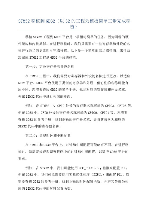
STM32移植到GD32(以32的工程为模板简单三步完成移植)移植STM32工程到GD32平台是一项相对简单的任务,因为两者的硬件架构和内核类似。
在进行移植时,我们只需要对一些寄存器和外设的名称进行适当的更改即可完成移植。
以下是一个简单的三步骤指南,来帮助您完成STM32工程到GD32平台的移植。
第一步:更改寄存器和外设名称在STM32工程中,我们需要对寄存器和外设的名称进行更改,以适应GD32平台。
GD32平台使用了类似的寄存器和外设,但它们的名称可能有所不同。
您需要查阅GD32的参考手册,找到对应的寄存器和外设名称,并在STM32代码中进行相应的更改。
例如,在STM32中,GPIO外设的寄存器名称可能为GPIOA、GPIOB等,但在GD32中,GPIO外设的寄存器名称可能为GPIO0、GPIO1等。
您需要查找GD32的参考手册,找到正确的寄存器名称,并将其替换为相应的STM32代码中的寄存器名称。
第二步:调整时钟和中断配置在STM32和GD32平台上,时钟和中断配置可能略有不同。
在进行移植时,您需要检查和调整代码中的时钟和中断配置,以适应GD32平台的要求。
例如,在STM32中,我们可能使用RCC_PLLConfig函数来配置PLL,但在GD32中,我们可能需要使用零延迟锁相环(ZZPLL)来配置PLL。
您需要查找GD32的参考手册,找到正确的时钟配置函数,并将其替换为相应的STM32代码中的时钟配置函数。
同样地,在移植中,您还需要检查和调整代码中的中断配置,以确保它们与GD32平台兼容。
第三步:验证和调试完成以上两个步骤后,您可以编译和烧录移植后的代码到GD32开发板上进行验证和调试。
您可能需要对一些功能进行逐个测试,以确保它们在GD32平台上正常工作。
在调试过程中,您可能会遇到一些问题和错误。
这是正常现象,您需要逐一解决这些问题,直到移植后的代码在GD32平台上完全正常运行。
总结这是一个简单的三步指南,帮助您将STM32工程移植到GD32平台。
基于STM32的uCOS-II移植详解

main.c
4/24
#include “led.h” static void delay(uint32_t ms){
uint32_t count = 8000; while (ms--) {
while (count--); count = 8000; } }
int main(void){ led_init(); for (;;) {
跑马灯程序
现在可以使用stm32标准外设库了,下面以一个简单的跑马灯程序说明。 在init目录下建立main.c作为系统入口。
在src下建立一个bsp目录用来放置板级支持代码,建立led.c,led.h。 代码如下: led.h
#ifndef _LED_H_ #define _LED_H_
#include <stdint.h> #define LED_0 0 #define LED_1 1 #define LED_2 2
将UV4中project window里的顶层目录名改为template,并将第一个group名改为 libstm32。把libstm32目录下所有.c和.s文件加载到工程里的libstm32。
在src下建立一个init目录用来放置系统初始化代码。把 Project\STM32F10x_StdPeriph_Template\下的stm32f10x_it.c拷贝到init文件夹中, stm32f10x_it.h,stm32f10x_conf.h拷贝到include文件夹中。
使用stm32标准外设库
Байду номын сангаас2/24
事实上,stm32标准外设库的使用在stm32f10x_stdperiph_lib_um.chm中的How to use the Library一节中已有说明,下面我把其中的步骤罗列一下: 1. 根据所选芯片,把Libraries\CMSIS\CM3\DeviceSupport\ST\STM32F10x\startup\arm 中的启动代码加到工程中,这一步在上面已经做过了。 2. 在stm32f10x.h的66-73行,根据所选芯片类型,去掉相应注释,这里我去掉 STM32F10X_HD行的注释(大容量型stm32芯片)。 3. 去掉105行的USE_STDPERIPH_DRIVER注释,启用stm32标准外设库。 4. 在system_stm32f10x.c的110-115行,根据所选芯片主频,去掉相应注释,默认 SYSCLK_FREQ_72MHz注释已去掉,如果你的芯片主频是72MHz,就不用做修改了,这 里我的芯片是36MHz,注释SYSCLK_FREQ_72MHz,去掉SYSCLK_FREQ_36MHz注释。
物联网操作系统原理(LiteOS)11实验环境配置

• ARM Cortex-M0 • ARM Cortex-M3 • ARM Cortex-M4 • ARM Cortex-M7
3
硬件环境
• 野火 STM32F429IG 开发板
4
硬件环境
• 野火 STM32F429IG 开发板
• 主芯片:ARMCortex-M4系列的STM32F429 • Flash容量:1MB • RAM容量:256KB • 板载模块
• 集成开发工具
• LiteOS Studio
• 实验环境准备
23
实验环境准备
• 工程烧录
• 在工具栏中打开“工程配置”,更改编译输出
20
实验环境准备
• 工程烧录
21
实验环境准备
• 串口终端配置
• 底部控制台选择串口终端 • 设备端口号和波特率 • 打开串口 • 观察开发板的输出信息
22
小结• 硬件环境• 火 STM32F429IG 开发板 • 小熊派开发板
• 开发板连接驱动 • LiteOS Studio
13
实验环境准备
• Huawei LiteOS 工程导入
• 通过github获取完整代码包
14
实验环境准备
• 工程导入
• 打开LiteOS Studio导入工程
15
实验环境准备
• 工程导入
• 配置工程目录和Makefile文件
16
实验环境准备
• 工程导入
• 选择芯片型号
17
实验环境准备
• 工程导入
• 配置烧录器(小熊派使用ST-Link)
18
实验环境准备
• 代码编译
- 1、下载文档前请自行甄别文档内容的完整性,平台不提供额外的编辑、内容补充、找答案等附加服务。
- 2、"仅部分预览"的文档,不可在线预览部分如存在完整性等问题,可反馈申请退款(可完整预览的文档不适用该条件!)。
- 3、如文档侵犯您的权益,请联系客服反馈,我们会尽快为您处理(人工客服工作时间:9:00-18:30)。
Huawei LiteOS 在STM32系列处理器上的移植
HUAWEI TECHNOLOGIES CO., LTD.
提纲
Huawei LiteOS支 持的移植 平台简介
Kernel源 码获取途 径
源代码框 架及介绍
移植环境 准备
移植过程 讲解
函数最后加上 ALIGN ;对齐伪指定 AREA KERNEL, CODE, READONLY THUMB
修改TaskSwitch函数,最后添加
NOP ALIGN
END
HUAWEI TECHNOLOGIES CO., LTD. Huawei Confidential 16
步骤三
根据芯片类型适配硬件资源
HUAWEI TECHNOLOGIES CO., LTD.
Huawei Confidential
17
步骤三
根据芯片类型适配硬件资源
二:修改los_hwi.c和对应的头文件,配置中断
根据STM32启动文件修改PendSV_Handler异常向量和SysTick_Handler向 量的名称
Huawei LiteOS源码中,他们分别叫osPendSV、osTickHandler。
36000000 15 0x00008000 SIZE(0x2D0) // default stack 16
#define LOSCFG_BASE_CORE_TSK_DEFAULT_STACK_SIZE
添加用户任务入口函数
extern UINT32 osAppInit(VOID);
该函数需要用户去实现,用户创建的系统任务都在该函数中注册,该函数会被
MDK和IAR中内嵌汇编写法不一致。故 修改,也可以使用MDK内嵌汇编 __asm VOID osTaskExit(VOID) { CPSID I }
一:修改los_hw.c和对应的头文件,配置相关寄存器
修改los_hw.c文件中的osTaskExit函数(los_hw.c 行号:90左右)
LITE_OS_SEC_TEXT_MINOR VOID osTaskExit(VOID) { __disable_irq(); while(1);
Huawei Confidential
12
移植Huawei LiteOS的主要步骤概述
1.在集成开发环境中添加Huawei LiteOS源码 2.适配系统调度汇编文件(los_dispatch.s) 3.根据芯片类型适配硬件资源(los_hw及los_hwi) 4.配置系统参数(los_config.h) 5.修改分散加载文件 6.解决部分常见移植代码编译错误
操作系统 任务创建 示例
HUAWEI TECHNOLOGIES CO., LTD.
Huawei Confidential
2
Huawei LiteOS目前支持的移植平台简介
一:ARM系列处理器 ARM9 ARM11 ARM cortex A系列:ARM cortex A7 ARM cortex A53 ARM cortex M系列:M0,M3,M4,M7 典型示例:海思IPC Camera(ARM cortex A7 ) STM32系列处理器 NB-IoT芯片(boudica)
HUAWEI TECHNOLOGIES CO., LTD.
Huawei Confidential
14
包含Huawei LiteOS头文件
在MDK工程上右键选择Options for Target…,然后在弹出工程配置对话框中选 择C++选项卡,添加包含路径,工程的所有包含目录如下图所示
HUAWEI TECHNOLOGIES CO., LTD.
HUAWEI TECHNOLOGIES CO., LTD.
Huawei Confidential
5
提纲
Huawei LiteOS支 持的移植 平台简介
Kernel源 码获取途 径
源代码框 架及介绍
移植环境 准备
移植过程 讲解
操作系统 任务创建 示例
HUAWEI TECHNOLOGIES CO., LTD.
los_config.c中的系统main函数调用。
HUAWEI TECHNOLOGIES CO., LTD.
Huawei Confidential
19
步骤五 修改MDK分散加载文件sct
由于Huawei LiteOS中对数据和代码位置进行了控制,代码和数据会放在多个不 同的内存区域,因此需要使用分散加载文件进行描述,要是系统准确运行起来, 需要重新编写一个分散加载文件。
Huawei Confidential
9
软件环境需求
主流的 ARM cortex M 系列微控制器集成开发环境
IAR 华为开发者社区开源的工程基于该IDE 需要自行安装插件,调试环境需要配置 GCC + Eclipse
MDK
本次移植使用的IDE
MDK安装需求
1.安装MDK5.2.1 下载地址:
}
osTskStackInit 函数中注释掉浮点代码( los_hw.c 行号:115) los_hw.h文件中修改TSK_CONTEXT_S结构体,删除浮点相关成员
说明:los_hw模块涉及CPU硬件相关配置, 移植的时候需要根据具体的CPU资源进行 修改,我们移植的是M3,所以删除浮点 相关代码,如果是M4或者M7,浮点代码 不需要删除。
Kernel源 码获取途 径
源代码框 架及介绍
移植环境 准备
移植过程 讲解
操作系统 任务创建 示例
HUAWEI TECHNOLOGIES CO., LTD.
Huawei Confidential
4
Huawei LiteOS源码获取途径
Huawei LiteOS kernel源码下载地址
华为开发者社区: /ict/cn/site-iot/product/liteos Github: https:///Huawei/Huawei_LiteOS_Kernel
Huawei Confidential
18
步骤四 在los_config.h中配置系统参数
常用参数配置
#define OS_SYS_CLOCK #define LOSCFG_BASE_CORE_TSK_LIMIT #define OS_SYS_MEM_SIZE #define LOSCFG_BASE_CORE_SWTMR_LIMIT ….
Huawei Confidential
6
源代码框架及介绍
序号 1 一级目录 Kernel 二级目录 Base 平台无关的内核代码 说明
Include 2 Platform bsp
内核的相关头文件存放目录 系统配置文件 应用入口相关示例代码
cpu
硬件体系架构相关代码 汇编调度代码
HUAWEI TECHNOLOGIES CO., LTD.
HUAWEI TECHNOLOGIES CO., LTD.
Huawei Confidential
11
提纲
Huawei LiteOS支 持的移植 平台简介
Kernel源 码获取途 径
源代码框 架及介绍
移植环境 准备
移植过程 讲解
操作系统 任务创建 示例
HUAWEI TECHNOLOGIES CO., LTD.
LITE_OS_SEC_TEXT_MINOR __asm UINT32 osIntNumGet(VOID) { MRS R0, wi.h文件中(行号243)把_BootVectors[]修改成__Vectors[]
HUAWEI TECHNOLOGIES CO., LTD.
二: Intel 处理器 典型示例:Intel® Quark™ SE平台
三: Tensilica的DSP处理器 典型示例: Xtensa LX7及LX4系列DSP
HUAWEI TECHNOLOGIES CO., LTD. Huawei Confidential 3
提纲
Huawei LiteOS支 持的移植 平台简介
其中.vector.bss需要在los_builddef.h文件中进行配置,将该文件第90行的宏定义注释 取消掉,修改后如下:
开发板硬件: 板载STM32F103、 STM32F4、 STM32F7 全系列芯片中任意一 款开发板或者最小系统板。 仿真器:ULINK、JLINK、ST-Link、符合CMSIS-DAP标准的Debugger等。 串口模块:开发板、最小系统板板载USB转串口模块或者RS232串口,没有的话 也可自行外接USB转TTL模块(CP2102 CH340 PL2303等USB转TTL模块)。 外设:GPIO可控的LED指示灯,用来创建Demo应用。
Huawei Confidential
7
提纲
Huawei LiteOS支 持的移植 平台简介
Kernel源 码获取途 径
源代码框 架及介绍
移植环境 准备
移植过程 讲解
操作系统 任务创建 示例
HUAWEI TECHNOLOGIES CO., LTD.
Huawei Confidential
8
硬件环境需求
内核源码位于Huawei_LiteOS\kernel\base目录下,我们把子目录core、ipc、 mem、misc目录下的c文件全部添加进来,一共15个文件。 添加bsp\sample\config下的los_config.c,cpu\arm\cortex-m4子目录下的 los_dispatch.s、los_hw.c、los_hw_tick.c、los_hwi.c,一共5个文件。