2160238 嵌入式系统设计1(中英文)(2011)
《嵌入式系统设计》课程教学大纲

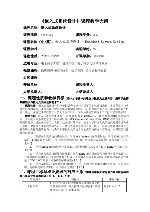
《嵌入式系统设计》课程教学大纲课程名称:嵌入式系统设计课程代码:TELE2131 课程学分:2.5课程名称(中/英):嵌入式系统设计 / Embedded System Design 课程学时:27 实验学时:27课程性质:大类专业课程开课学期:第*学期适用专业:电子信息工程、通信工程、电子科学与技术等专业先修课程:微机原理与接口技术、数字电路、C语言程序设计后续课程:开课单位:课程负责人:大纲执笔人:大纲审核人:一、课程性质和教学目标(在人才培养中的地位与性质及主要内容,指明学生需掌握知识与能力及其应达到的水平)课程性质:嵌入式系统设计是电子信息类专业一门重要的专业选修课程。
本课程是一门实践性很强的课程,课程以理论教学与实验教学并重的方式,培养学生嵌入式技术方面的软硬件设计能力,并通过该课程的学习扩大学生知识面,为今后的研究和技术工作打下坚实的基础。
教学目标:嵌入式系统设计以ST公司的32位基于ARM Cortex﹣M3内核的STM32单片机为例,介绍嵌入式系统的定义、特点和发展;ARM Cortex﹣M3体系结构;STM32程序设计与片上外围资源等,通过理论学习、实验、综合设计等环节,使学生了解嵌入式系统的发展状况和应用领域,掌握嵌入式系统的硬件设计、软件设计和系统综合设计能力,培养学生利用本课程分析和解决实际问题的能力,为今后从事嵌入式系统方面的应用与研究打下基础。
本课程的具体教学目标如下:1、掌握嵌入式系统的基础知识;学习ARM Cortex﹣M3体系结构;学习STM32 MCU的结构、STM32最小系统、片内外设资源和外部引脚,学习嵌入式系统硬件分析和设计方法;【1-2】2、学习STM32 MCU的软件开发技术,掌握利用嵌入式C语言设计STM32程序的方法;【1-2】3、学习嵌入式系统硬件设计技术,掌握STM32最小系统硬件和外围扩展单元设计,并能够综合运用嵌入式系统软件和硬件设计技术解决实际工程问题,并能够根据需求设计基于STM32 MCU的嵌入式系统的解决方案;【3-1】4、学习ARM Keil集成开发环境的使用方法,熟练使用STM32 MCU开发板,并在此基础上完成规定的必修实验,设计综合性实验。
《嵌入式系统设计》课程教学大纲(本科)

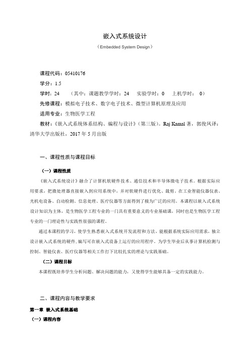
嵌入式系统设计(Embedded System Design)课程代码:05410176学分:1.5学时:24 (其中:课题教学学时:24 实验学时:0 上机学时:0)先修课程:模拟电子技术、数字电子技术、微型计算机原理及应用适用专业:生物医学工程教材:《嵌入式系统体系结构、编程与设计》(第三版)。
Raj Kamal著,郭俊凤译:清华大学出版社,2017年5月出版一、课程性质与课程目标(一)课程性质《嵌入式系统设计》融合了计算机软硬件技术、通信技术和半导体微电子技术。
根据实际应用要求,把微处理器直接嵌入到应用系统中,并对软硬件进行优化、裁剪。
在工业智能仪器仪表、光机电设备、自动检测、信息处理、医疗仪器等方面得到了极为广泛的应用。
本课程以嵌入式系统设计知识为主体,是生物医学工程专业的一门具有重要意义的专业基础课,同时也是生物医学工程专业的一门理论性与实践性很强的课程。
通过本课程的学习,使学生熟悉嵌入式系统开发流程和方法,能根据系统实际应用需求,独立设计嵌入式系统的硬件,编写可在嵌入式设备上运行的应用程序。
为学生毕业后从事计算机检测与控制、智能仪表、医疗仪器等相关工作打下比较扎实的理论与实践基础。
(二)课程目标本课程既培养学生分析问题、解决问题的能力,又使得学生能够具备一定的实践能力。
二、课程内容与教学要求第一章嵌入式系统基础(一)课程内容1. 嵌入式系统概念2. 嵌入式系统处理器3 嵌入式操作系统(二)教学要求1. 正确理解嵌入式系统的基本概念2. 掌握嵌入式微处理器分类及结构3. 掌握嵌入式操作系统的概念及内核4. 了解嵌入式系统的发展趋势(三)重点与难点1. 重点(1)嵌入式系统的概念(2)嵌入式处理器(3)嵌入式操作系统2. 难点(1)嵌入式微处理器(2)嵌入式操作系统的内核第二章嵌入式系统开发流程(一)课程内容1. 嵌入式软件开发特点2. 嵌入式软件开发流程3. 嵌入式系统的调试(二)教学要求1. 熟悉嵌入式软件开发特点2. 掌握嵌入式软件开发流程3. 掌握嵌入式系统的调试(三)重点与难点1. 重点:嵌入式软件开发流程2. 难点:嵌入式系统的调试第三章嵌入式系统的硬件基础(一)课程内容1. 嵌入式系统的硬件结构2. 嵌入式系统的处理器3. 嵌入式系统的存储器4. 嵌入式系统的其他电路(二)教学要求1. 熟悉嵌入式系统的硬件结构2. 了解嵌入式系统的处理器3. 掌握嵌入式系统的存储器4. 掌握嵌入式系统的其他电路(三)重点与难点1. 重点:(1)嵌入式系统的硬件(2)嵌入式系统的处理器2. 难点:嵌入式系统的硬件第四章嵌入式系统的软件基础(一)课程内容1. 嵌入式系统的集成开发环境2. 嵌入式系统的软件架构3. 嵌入式系统的常用软件模块(二)教学要求1. 熟悉嵌入式系统的集成开发环境2. 掌握嵌入式系统的软件架构3. 掌握嵌入式系统的常用软件模块(三)重点与难点1. 重点:(1)嵌入式系统的软件架构(2)嵌入式系统的常用软件模块2. 难点:嵌入式系统的常用软件模块第五章嵌入式操作系统基础(一)课程内容1. 嵌入式操作系统概述2. 嵌入式操作系统内核的结构(二)教学要求1. 了解常用的.嵌入式操作系统2. 掌握嵌入式操作系统内核的结构(三)重点与难点1 重点:嵌入式操作系统内核的结构2. 难点:嵌入式操作系统内核的结构三、本课程开设的实验项目四、学时分配及教学方法六、参考书目及学习资料1. 《嵌入式系统开发与应用教程》田泽编著.北京航空航天大学出版社,2010.2. 《嵌入式系统硬件与软件架构》Tammy Noergaard著,马洪兵译.人民邮电出版社,2008.3. 《嵌入式操作系统基础µC/OS-Ⅱ和Linux》任哲,樊生文.北京航空航天大学出版社,2011.七、大纲说明1. 采用多媒体教学手段,建议采用讲授、案例、讨论相结合,多种教学手段综合运用。
《嵌入式系统分析与设计》课程教学大纲

《嵌入式系统分析与设计》课程教学大纲第一篇:《嵌入式系统分析与设计》课程教学大纲《嵌入式系统分析与设计》课程教学大纲一、课程基本信息中文名称:嵌入式系统分析与设计英文名称:Embedded System Design 开课学院:计算机科学学院学分:2 修读基础: 数字电路、微机原理、C语言课程负责人:郑巧(副教授)主讲教师:郑巧(副教授)二、课程目的任务1.课程地位作用(课程在实现培养目标中的地位作用)培养学生具有嵌入式系统的应用知识、嵌入式系统的分析能力和具有用RTOS构成嵌入式系统的应用能力。
2.课程主要内容(简述:主要内容、重点、难点等)主要介绍嵌入式系统更广泛的概念、设计思想和其他技术,围绕32位ARM处理器和源码开放的Linux操作系统,讲述嵌入式系统的概念、软硬件组成、开发过程以及嵌入式Linux和基于Linux的应用程序开发方法。
3.学生应达到的基本要求通过本课程的学习,应掌握嵌入式系统软硬件设计的基本方法;理解嵌入式系统的概念和基本要素;运用所学的专业基础理论、基本技能和专业知识分析问题和解决工程设计问题的能力,具有调查研究,查阅技术文献、资料、手册,进行程序设计、电路图纸绘制及编写技术文件的基本能力。
三、教学内容与学时分配(含各时段学生课外学习要求)1、绪论(2学时)教学内容:(1)嵌入式系统的概念(2)嵌入式微处理器(3)嵌入式操作系统(4)嵌入式系统的开发过程教学要求:(1)了解嵌入式系统的概念(2)了解嵌入式微处理器(3)理解嵌入式操作系统(4)理解嵌入式系统的开发过程课程编码:S0812402 总学时:32 适用专业:计算机科学与技术学术硕士,计算机技术专业硕士2、ARM体系结构(6学时)教学内容:(1)ARM体系结构(2)ARM编程模型(3)ARM基本寻址方式(4)ARM指令集(5)Thumb指令集(6)ARM7TDMI、ARM9TDMI、ARM10E 处理器内核系列及指令执行分析教学要求:(1)理解ARM体系结构的特点(2)掌握ARM编程模型(3)掌握ARM 基本寻址方式(4)掌握ARM指令集(5)了解Thumb指令集(6)了解ARM7TDMI、ARM9TDMI、ARM10E 处理器内核系列及指令执行过程3、嵌入式软件开发(8学时)教学内容:(1)ARM汇编语言程序设计(2)ARM 和 Thumb 指令交互工作(3)异常及异常处理(4)ARM 编程(5)嵌入式C语言程序开发(6)基于 ARM 的软件开发调试技术教学要求:(1)掌握ARM汇编语言程序设计(2)理解ARM 和Thumb 指令交互工作机制(3)掌握ARM的异常处理机制(4)掌握嵌入式C语言开发方法(5)掌握基于 ARM 的软件开发调试技术4、嵌入式系统硬件开发(8学时)教学内容:(1)最简的嵌入式系统(2)电源、复位、时钟和JTAG接口(3)存储系统及初始化(4)嵌入式系统接口设计(5)系统硬件电路设计(6)启动代码设计(7)程序固化与综合调试技术教学要求:(1)理解最简的嵌入式系统(2)掌握电源、复位、时钟和JTAG接口电路(3)掌握存储系统及初始化方法(4)掌握常见接口设计方法(5)掌握启动代码设计(6)理解程序固化与综合调试技术5、嵌入式Linux操作系统(4学时)教学内容:(1)Linux系统及其内核特征(2)Linux的内核管理(3)嵌入式Linux 的引导过程(4)嵌入式Linux的实时化改造教学要求:(1)了解Linux系统及其内核特征(2)了解Linux的内核管理(3)了解嵌入式Linux的引导过程(4)掌握嵌入式Linux的实时化改造6、嵌入式Linux应用程序开发(4学时)教学内容:(1)开发环境的建立(2)应用程序的开发与调试方法教学要求:(1)了解如何建立开发环境(2)掌握应用程序的开发与调试方法四、考核方式与成绩评定1.考核方式:(笔试、论文、口试等)论文2.成绩评定办法:(平时成绩、期末考试成绩……等比例)平时成绩:应根据学习纪律、出勤、等方面综合评定,占20%;设计报告:根据学生设计报告各部分的完整性和优劣情况评定,占60%;设计答辩:应根据答辩结果评定,占20%.五、教材及主要参考书目1.周立功编,ARM嵌入式系统基础教程,北航出版社2.嵌入式系统-采用公开源代码和StrongARM/XScale处理器,毛德操等编,浙江大学出版社,2003。
《嵌入式系统设计》课件

2
系统架构设计
设计系统的硬件和软件架构,包括选择适当的处理器和外设。
3
电路设计
设计电路板,包括选择元件、布线和进行电路仿真。
4
软件开发
编写嵌入式软件,实现系统功能和交互。
嵌入式系统硬件设计
电路设计
微控制器
通过选择合适的元件和进行布线, 设计控制器,如 Arduino或Raspberry Pi,以实现 系统的处理和控制。
《嵌入式系统设计》PPT 课件
嵌入式系统是指将计算机技术和信息处理能力嵌入到特定应用领域中的系统。
嵌入式系统简介
嵌入式系统是一种特殊的计算机系统,集成了软硬件设计,广泛应用于生活中的各个方面,如智能家居、汽车 电子和医疗设备。
嵌入式系统设计流程
1
需求分析
根据需求和系统特点确定设计目标和主要功能。
嵌入式系统应用于医疗设备中, 如心脏起搏器和医疗监测仪器, 提供精准和可靠的医疗服务。
总结与提问
嵌入式系统设计是一个综合性的过程,需要考虑硬件和软件的协同工作,以 实现特定应用领域的需求。欢迎提问和讨论。
传感器
选择适当的传感器,如温度、湿 度或距离传感器,以实现系统的 感知能力。
嵌入式系统软件设计
嵌入式编程语言
选择适当的编程语言,如C或C++,以实现嵌入式系统的软件功能。
实时操作系统
使用实时操作系统(RTOS)来管理系统的任务和资源,保证系统的实时性。
驱动程序开发
开发设备驱动程序,以实现与外设的通信和控制。
嵌入式系统调试与测试
调试和测试是嵌入式系统设计过程中至关重要的一环,涉及硬件和软件的运 行状态、故障排除和性能评估。
嵌入式系统应用实例
第一章、嵌入式系统设计概论 ppt课件

在制造工业、过程控制、通讯、仪器、仪表、 汽车、船舶、航空、航天、军事装备、消费类 产品等方面均是嵌入式计算机的应用领域。
ppt课件
12
经典应用
CISCO的路由器 华为、中兴的以太网交换机 恒基伟业的商务通PDA; 摩托罗拉的手机 美国宇航局的火星探测器 Sony的机器狗AIBO
ppt课件 7
后PC技术的时代
小到mp3,PDA等微型数字化产品,大到 网络家电,智能家电,车载电子设备 嵌入式系统是这个后PC时代的擎天之柱 1999年世界电子产品产值已超过12000亿 美元,2000年达到13000亿美元,预计 2005年,销售额将达18000亿美元。
ppt课件
8
普适计算是指使用小型计算设备、在位置 不断移动的过程中或在地理位置分布很广 的范围内,在不稳定的通信条件下实现联 机事务处理和企业核心数据访问。 普适计算是指无所不在的、随时随地可以 进行计算的一种方式; 主要针对移动设备; 普适计算设备可以一直或间断地连接着网 络
ppt课件 22
普适计算和无线互联及网络计算比较
ppt课件
5
历史
电脑用于控制设备或嵌入系统的历史几乎 电脑自身的历史一样长 计算机控制系统 单片机掀起电子化浪潮 微处理器高速发展推动了嵌入式系统
ppt课件
6
嵌入式系统的演变
8031/8051单片机系统,自行编写程序; 68360/386EX控制系统,自己编写简单的 操作系统; 32位嵌入式处理器+pSoS嵌入式操作系 统+tcp/ip协议栈; 各种SoC+嵌入式Linux/VxWorks+嵌入式 Web 设备server以及各种复杂网络协议栈 +GUI图形界面+无线模块=现代可移动 的网络智能设备
嵌入式系统设计报告英文含代码

1.System Design SchemaThis system is called speech spectrum analyzer based on the development tools called TM320C6416. The software is tested on code composer studio 6416(CCS6416). The system can realize the function that It can analyse the spectrum of the speech signals inputted by fast fourier transform(FFT) algorithm, and then print the frequency by ergodic algorithm, which can help find the number of the maxmum magnitude location . In addition, the system also can paly the voice which was recoded before. The C6X is used to designate a member of Texas Instruments’ (TI) TMS320C6000 family of digital signal processors. The architecture of the C6x digital signal processor is very well suited for numerically intensive calculations. The FFT with the radix-2 algorithm is a efficient algorithm that is used for converting a time-domain signal into an equivalent frequency-domine signal , based on the discrete frouier transform(DFT), The FFT reduces considerably the computational requirements of the DFT. The DFT of a discrete-time signal x (nT ) isNj N n nk e W N k W n x k X /2101......2,1,0 )()(π--==-==∑The FFT algorithm takes advantage of the periodicity and symmetry of the twiddle constants to reduce the computational requirements of the FFT. From the periodicity of W ,kk WN+W=and from the symmetry of Wk W+2/NkW-=An eight-point FFT is illustrated through the following exercise. We will see that flow graphs for higher-order FFT (larger N) can readily be obtained.figure1. Eight-point FFT flow graph using DITFor the reason that the speech signals recognition is quite hard ,so 512-point FFT has been adopted. After FFT algorithm finished, 512 magnitudes will be acquired. Then the maximum value will be found by the ergodic algorithm, and we can get the accurate frequency by the equation of number/max*_=, andf_samplefsnumberthen print it in CCS. Besides, I have set many flags to identify whether the frequency belongs to high frequency, or low frequency by the way of the LED turning on.2.Goal and Test Level of the system AchievedThe system can record the voice in surroundings, and then play what it records,besides, the system can also analyse the frequency of the recording voice by FFT algorithm. And t the analysed speech signal spectrum by C language can be a consistent with what is analysed by the built-in algorithm of CCS6416. I have compared the result produced by C language and the result of the CCS6416’s built-in GUI FFT algorithm, and I can get the perfect accordance with just 0.002% deviation. So the system can reach to the purpose accurately.3.Block Diagram and Flow Chart of System ImplementationThis system consists of three parts, one is speech signal acquisition module, and another is signal processing module, which is finished by STM320C6416 and FFT algorithm, and the last is speech sognal output module.Block Diagram is showed in figure2:figure2 block biagram of speech signal spectrum analysis systemFlow chat of system is shown in figure3:f igure3 flow chart of speech signal spectrum analysis systemAfter burnprocess has been finished, the system is waiting. In the case of testing the switch has been pressed, the record function starts, and the record will finish in the condition that switch three has been uplifted or the buffer is been fulfilled with that can be observed if the LED three is off. And then if switch zero has been pressed, the system will begin to play what has record before, and playing is finished in the condition of switch zero is uplifted, the the FFT begin after LED one turning on. The frequency will be printed in the CCS6416, and while LED one turns off ,it means the FFT is over, and the whole function has been finished.4.the Key Point and Difficulties of System ImplementationThe key point of this system is the implement of FFT algorithm. FFT algorithm has to analyze the spectrum of speech signal accurately, which is hard for C language to implement. The difficulties of the system implementation lies on the FFT algorithm’s operatoring speed and accuracy. I adopted 512-point FFT analysis, and then I find the maximum magnitude by ergodic algorithm, which has to compare all 512 points with each other to find the maxmum magnitude. There is no doubt that it istime-consuming. So the system can not fulfilled the real-time capability of computing magnitude.5.Core Code and Explanation of SystemThe code of the system is listed as follows://record.c record/play input using external memory#include <stdio.h>#include "math.h"#include "dsk6416_aic23.h" //codec supportUint32 fs=DSK6416_AIC23_FREQ_8KHZ; //set sampling rateUint16 inputsource=DSK6416_AIC23_INPUT_MIC; // select inputunsigned long i,count,s;short buffer[N];short buffer1[SAMPLENUMBER];long m;float max;void InitForFFT();int INPUT[SAMPLENUMBER],DATA[SAMPLENUMBER];float fWaveR[SAMPLENUMBER],fWaveI[SAMPLENUMBER],w[SAMPLENUMBER]; float sin_tab[SAMPLENUMBER],cos_tab[SAMPLENUMBER];#pragma DATA_SECTION(buffer,".EXT_RAM") //buffer ->external memoryvoid main(){int q,t,n,m,l,tt=0;short playing = 0;•DSK6416_DIP_init();DSK6416_LED_init();comm_poll(); //init DSK, codec, McBSPInitForFFT();count=0;while(1) //infinite loop{if(DSK6416_DIP_get(3) == 0) //if SW#3 is pressed{DSK6416_LED_on(3); //turn on LED#3buffer[count++] = input_left_sample();}if(DSK6416_DIP_get(3) ==1||(count>=N-1)) //if SW#3 is pressed {DSK6416_LED_off(3);}}if(DSK6416_DIP_get(0)==0) //if SW#0 pressed{count=0;playing = 1;while (playing == 1){DSK6416_LED_on(0); //turn on LED#0output_left_sample(buffer[count++]);if(count>=N-1){DSK6416_LED_off(0);•for(s=50;s<N/SAMPLENUMBER;s++){n=0;for(l=SAMPLENUMBER*(s-1);l<s*512;l++){n=l-SAMPLENUMBER*(s-1);buffer1[n]=buffer[l];for(q=0;q<SAMPLENUMBER;q++) {fWaveR[q]=buffer1[q];fWaveI[q]=0.0f;}FFT(fWaveR,fWaveI);max=w[0];m=0;for(t=0;t<SAMPLENUMBER/2;t++){if(max<w[t]){max=w[t];m=t;}}}//for(l=SAMPLENUMBER*(s-1);l<s*512;l++) tt=m*8000/SAMPLENUMBER;if(tt>=1046&&tt<=1975){DSK6416_LED_on(1);DSK6416_LED_on(2);}else if(tt>513) DSK6416_LED_on(2);else if(tt>0) DSK6416_LED_on(1);else{DSK6416_LED_on(3);DSK6416_LED_on(1);DSK6416_LED_on(2);}if(tt>25)printf("%d\n",tt);DSK6416_LED_off(1);DSK6416_LED_off(2);DSK6416_LED_off(3);}//for(s=1;s<N/SAMPLENUMBER;s++)count=0;} //if(count>=N-1)} // while (playing == 1)playing=0;DSK6416_LED_on(0);} //if(DSK6416_DIP_get(0)==0)}//while(1)}//mainvoid FFT(float dataR[SAMPLENUMBER],float dataI[SAMPLENUMBER]) {int x0,x1,x2,x3,x4,x5,x6,x7,x8,xx;int i,j,k,b,p,L;float TR,TI,temp;/********** following code invert sequence ************/for ( i=0;i<SAMPLENUMBER;i++ ){x0=x1=x2=x3=x4=x5=x6=x7=x8=0;x0=i&0x01; x1=(i/2)&0x01; x2=(i/4)&0x01; x3=(i/8)&0x01;x4=(i/16)&0x01; x5=(i/32)&0x01; x6=(i/64)&0x01;x7=(i/128)&0x01;x8=(i/256)&0x01;//x=x0*1024+x1*512+x2*256+x3*128+x4*64+x5*32+x6*16+x7*8+x8*4+x9*2+x10;xx=x0*256+x1*128+x2*64+x3*32+x4*16+x5*8+x6*4+x7*2+x8;dataI[xx]=dataR[i];}for ( i=0;i<SAMPLENUMBER;i++ ){dataR[i]=dataI[i]; dataI[i]=0;}/************** following code FFT *******************/for ( L=1;L<=9;L++ ){ /* for(1) */b=1; i=L-1;while ( i>0 ){b=b*2; i--;} /* b= 2^(L-1) */for ( j=0;j<=b-1;j++ ) /* for (2) */{p=1; i=9-L;while ( i>0 ) /* p=pow(2,7-L)*j; */{p=p*2; i--;}p=p*j;for ( k=j;k<SAMPLENUMBER;k=k+2*b ) /* for (3) */{TR=dataR[k]; TI=dataI[k]; temp=dataR[k+b];dataR[k]=dataR[k]+dataR[k+b]*cos_tab[p]+dataI[k+b]*sin_tab[p];dataI[k]=dataI[k]-dataR[k+b]*sin_tab[p]+dataI[k+b]*cos_tab[p];dataR[k+b]=TR-dataR[k+b]*cos_tab[p]-dataI[k+b]*sin_tab[p];dataI[k+b]=TI+temp*sin_tab[p]-dataI[k+b]*cos_tab[p];} /* END for (3) */} /* END for (2) */} /* END for (1) */for ( i=0;i<SAMPLENUMBER;i++ ){w[i]=sqrt(dataR[i]*dataR[i]+dataI[i]*dataI[i]);}} /* END FFT */Firstly, I set the sampling fruquency as 8 Khz, and the total buffer number is 512000which means that it can record the voice as long as 64 seconds. The core of the code includes three parts. One is the recording part, and the second is playing part, and the third is the FFT analysis part. While the DSP chip detect the switch three was pressed, then recording starts. Recording is accomplished by the fuction called input_sample., which can complete the AD sampling and store the sampled value into buffer. LED three will turn off while the buffer has been filled or the switch three is uplifted. Then if you press switch zero, then playing starts, which can paly what has been recorded. And the playing part is accomplished by the function called output_sample, which can read the discrete value in the buffer and turn in to analogy speech signal. After the palying is over, LED zero will turn off, and LED one will turn on indicating that FFT with the radix-2analysis begins. FFT algorithm computing is accomplished by looking up to table, and the table is made up by the sine function and cosine fuction, we will get the real and imaginary parts of magnitudes. And then by the way of ergodic algorithm to find the accurate number of location of the maxmum magnitude. We will get the frequency by equation of numbermax*/_,numbersamplefsf_After the FFT finished, LED one will turn off, and the speech signal spectrum analyzer has fulfilled all function.6.Debugging Recording of System and Testing IllustrationEach time, FFT analyze 512 points. So I divide the whole buffer into lots of little buffer containing 512 points. The debugging processing mainly depends on the location of breakpoints. I set the breakpoint in the location of FFT analyze of each little buffer called buffer1, and when the code execute the location of breakpoint, I open the view of FFT analyze of CCS6416 built-in, and compared the result printed by the FFT algorithm realized by C language and the result of the view of FFT to decide while they are the same with each other, or just with a little deviation. When the breakpoint was set in the location of first 512-point buffer, the result is in the below:And the second 512-point buffer compareing results is shown in the figure5:figure5 the compareing result of the second 512-point buffer7.Result of SystemThe testing can proved that the result of the system can reach to the ideal propose, which not only can play the voice of what has been recorded, but also can accuratelyobtain the frequency of the voice, just with devation of less then 0.002%.评分注: 1 无评卷人签名试卷无效。
嵌入式系统专业术语中英文对照

BMC:Burst Mode Controller 突发模式控制器
BMS:Building Management System 智能建筑管理系统
BRI:Basic Rate ISDN 基本速率的综合业务数字网
BS:Base Station基站
BSC:Base Station Controller基站控制器
CDDI:Copper Distributed Data 合同缆分布式数据接口
CDES:Carbon dioxide extinguisbing system 二氧化碳系统
CDMA:Code Division Multiplex Access 码分多址
CF:Core Function 核心功能
CFM:Compounded Frequency Modulation 压扩调频繁
AF:Acoustic Feedback 声反馈
AFR:Amplitude /Frequency Response 幅频响应
AGC:Automati Gain Control自动增益控制
AHU:Air Handling Unit 空气处理机组
A-I:Auto-iris自动光圈
AIS:Alarm Indication Signal 告警指示信号
DWDM:Dense Wave-length Division Multiplexing 密集波分复用
DXC:Digital Cross-Connect 数字交叉连接
E:Emergency lighting照明设备
E:Equalizer 均衡器
E:Expander 扩展器
嵌入式系统设计EmbeddedSystemDesign

44
1.12 需要具备的能力:系统整合能力(2)
产 品 设 计 人力需求 开发工时 设备成本 原料成本 定价 目 标 市 场 生命周期 产品价值 市场潜力 竞 争 优 势 开发界面人性化 快速模块化 高兼容性 全程设计 附 加 价 格
28
1.6.2 RTOS编程和传统编程的区别
数据采集终端:采集,处理,键盘,LCD显示,微打
数据采集 数据采集 处理数据 处理键盘 显示 处理数据
中断
处理键盘 RTOS 中断
中断
显示 打印
打印
传统编程
基于RTOS编程
29
1.7 工具链的选择(1)
嵌入式系统的一个特点在于其开发的特殊性 与困难性。 开发机器 != 执行机器 开发环境 != 执行环境 专门的开发环境与开发工具
13
1.6 嵌入式系统的基本组成(2)
硬件系统
嵌入式处理器 各种类型存储器 模拟电路及电源 接口控制器及接插件
嵌入式软件系统
实时操作系统(RTOS) 板级支持包(BSP) 设备驱动(Device Driver) 协议栈(Protocol Stack) 应用程序(Application)
34
Coldfire PPC
1.7 嵌入式系统的开发环境
Modem Linux/PC服务器 Internet
PSTN Modem 笔记本电脑
ห้องสมุดไป่ตู้
以太网
串行线 Windows工作站 BDM电缆 开发板
串行线 Linux/PC工作站 BDM电缆 开发板
35
1.8 基于Xilinx FPGA的SOPC设计
- 1、下载文档前请自行甄别文档内容的完整性,平台不提供额外的编辑、内容补充、找答案等附加服务。
- 2、"仅部分预览"的文档,不可在线预览部分如存在完整性等问题,可反馈申请退款(可完整预览的文档不适用该条件!)。
- 3、如文档侵犯您的权益,请联系客服反馈,我们会尽快为您处理(人工客服工作时间:9:00-18:30)。
天津大学《嵌入式系统设计1》课程教学大纲课程代码:2160238 课程名称:嵌入式系统设计1学 时: 40 学 分: 2学时分配: 授课:24 上机: 实验:16 实践: 实践(周): 授课学院: 计算机科学与技术学院适用专业: 计算机科学与技术先修课程: 数字逻辑计算机组成原理汇编语言一.课程的性质与目的嵌入式计算机系统是指以应用为核心,以计算机技术为基础,其软硬件可配置,对功能、可靠性、成本、体积、功耗有严格约束的一种专用计算机系统。
21世纪是嵌入式系统时代,由于其功能齐全、功耗低、可靠性高、适应面广等诸多特点,人们日常生活和工作中所接触的仪器与设备都离不开嵌入式计算机系统,围绕嵌入式系统展开研究。
本课程旨在改变嵌入式技术教育滞后的局面,帮助学生全面掌握嵌入式系统的基本原理及设计开发方法。
二.教学基本要求通过本课程的学习,首先使学生全面了解嵌入式系统的概念、组成及特点,硬件平台构建,嵌入式操作系统、网络技术的相关知识;掌握嵌入式计算机系统的设计原则及设计步骤;深入了解嵌入式系统各个组成部分具体的设计方法,包括:嵌入式处理器的选择原则,总线设计,内存储器的设计,各种常用外设接口的设计,系统的可靠性设计,系统的调试等。
学生在完成本课程的学习后,能独立设计一个小型的嵌入式计算机系统。
三.教学内容第一章 嵌入式系统设计概述1. 嵌入式计算机系统2. 嵌入式计算机系统的设计要求和设计步骤第二章 嵌入式处理器1. 嵌入式处理器简介2. 选择嵌入式处理器第三章 总线设计1.总线概述2.内总线与外总线3.总线驱动与控制第四章 存储系统设计1.存储系统设计概述2. 存储器地址译码方式及译码电路3.RAM的连接4.EPROM和EEPROM第五章 嵌入式系统常用接口1. 常用接口2. 数/模(D/A)变换器接口3.模/数(A/D)变换器接口4. 步进电机与直流电机接口5. 中断的应用第六章 用户程序开发1. 软件开发模式简述2. 用户程序的基本要求及开发过程3. 高级语言与汇编语言的接口第七章 实时监控程序1.概述2.实时监控程序设计第八章 嵌入式系统的可靠性设计1.概述2.故障检测技术3.硬件及软件的可靠性设计4.系统的抗干扰设计5.可靠性的总体考虑第九章 系统调试与维修1.测试仪器简介2.嵌入式计算机系统的调试3.系统故障的检测与维护实验内容1. 实验一:SOPC实验箱的使用2. 实验二:按键和显示器驱动(LED、LCD)3. 实验三:电机驱动及测速(直流电机、步进电机)4. 实验四:综合设计练习(大作业)四.学时分配教学内容 授课 上机 实验 实践 实践(周)第一章 2第二章 2第三章 2第四章 4第五章 4第六章 4 4第七章 2 4第八章 2 4第九章 2 4总计: 24 16五.评价与考核方式课程总成绩包含平时成绩和期末考试成绩两部分:以实验作业为主计算平时成绩,占总成绩的40%;期末考试成绩占60%。
实验作业逐一验收,需要做现场演示,并回答验收教师的随机提问。
期末闭卷考试。
六.教材与主要参考资料教材:微型计算机嵌入式系统设计 李伯成编著 西安电子科技大学出版社ISBN 7-5606-1377-2参考书:1. 嵌入式系统设计原理与应用 符意德编著 清华大学出版社ISBN 7-302-09638-42. 嵌入式计算系统设计原理 (美)Wayne Wolf著 机械工业出版社ISBN 7-111-09640-13. 嵌入式系统原理及应用开发技术 桑楠著 北京航空航天大学出版社ISBN 7-81077-164-7制定人:审核人:批准人:批准日期:年月日TU Syllabus for Embedded System Design 1Code:2160238 Title: Embedded System Design 1Semester Hours: 40Credits:2Semester Hour Structure Lecture : 24 Computer Lab : Experiment : 16 Practice :Practice (Week):Offered by: School of Computer Science and Technology for: Computer Science and Technology Prerequisite: Embedded System Design 11. ObjectiveEmbedded computer system refers to the application as the core, computer technology, software and hardware can be configured for functionality, reliability, cost, size, power consumption, there are strict constraints of a dedicated computer system. The 21st century is the era of embedded systems, because of its full-featured, low power consumption, high reliability, wide adaptation, and many other characteristics, people's daily life and work in contact with the instruments and equipment are inseparable from embedded computer systems around the a study of embedded systems. This course is designed to change the backward situation of embedded technology education to help students fully grasp the basic principles and embedded systems design and development methods.2. Course DescriptionThrough this course, the first so that students fully understand the concept of embedded systems, composition and characteristics of the hardware platform to build, embedded operating systems, network technology knowledge; of embedded computer system design principles and design procedures; in-depth understanding of specific components of embedded systems design methods, including: the choice of the principle of embedded processors, bus design, memory design, a variety of common peripheral interface design, system reliability design, system debugging. Students completing this course, we could design a small stand-alone embedded computer systems.3. TopicsChapter I Overview of Embedded System Design1. Embedded Computer Systems2. the design of embedded computer system requirements and design steps Chapter II Embedded processor1. Introduction to Embedded Processor2. Select the embedded processorChapter III Bus design1. Bus Overview2. Internal bus and external bus3. Bus driver and controlChapter IV Memory system design1. Storage System Design Overview2. memory address decoding method and decoding circuit3. RAM Connection4. EPROM and EEPROMChapter V Common interface to embedded systems1. Common Interface2. digital / analog (D / A) converter interfaces3. Analog / digital (A / D) converter interfaces4. stepper motors and DC Interface5. interrupt applicationsChapter VI User program development1. Software development model outlined2. the basic requirements of the user program and the development process3. high-level language and assembly language interfaceChapter VII Real-time monitoring program1. Outline2. Real-time monitoring program designChapter VIII The reliability of embedded systems design1. Outline2. Fault detection techniques3. The reliability of hardware and software design4. System anti-jamming design5. The overall reliability considerationsChapter IX System debugging and maintenance 1. About Test Equipment2. Debugging of embedded computer systems3. System fault detection and maintenanceExperimental content1 Experiment I: SOPC use of the kit2 Experiment 2: buttons and display drivers (LED, LCD)3 Experiment 3: motor drive and speed (DC motors, stepper motors)4 Experiment 4: integrated design practice (great job)4. Semester Hour StructureTopics Lecture ComputerLab. ExperimentPracticePractice (Week)Chapter 1 2 Chapter 2 2 Chapter 3 2 Chapter 4 4 Chapter 5 4 Chapter 6 4 4 Chapter 7 2 4 Chapter 8 2 4 Chapter 9 24Sum:24 165. GradingThe total score includes the usual course and final examination results in two parts: Experimental work to calculate the usual results-based, 40% of the total score; final examination 60%.Acceptance of each experimental work, you need to do a live demonstration, and acceptance of teachers to answer random questions. Final closed-book exam.6. Text-Book & Additional ReadingsMaterials: micro-computer embedded system design, Li Bocheng ed, Xi'an University Press, ISBN 7-5606-1377-2Constitutor:Reviewer:Authorizor:Date:。
