海底电缆登陆
海上风电场海缆登陆施工方案技术总结

海上风电场海缆登陆施工方案技术总结王忠锋与陆上风电场相比,海上风电场具有不占用土地资源、基本不受地形地貌影响、风能资源丰富、年利用小时数更高、风电机组单机容量更大、适宜大规模开发等优点,最近幾年得到蓬勃发展,促进了风电机组、船机设备、海底电力电缆(以下简称“海缆”)等相关产业加工制造与施工技术的进步。
海上升压站与陆上集控中心之间一般采用220kV/110kV光电复合缆连接,根据风电场发电容量要求的不同,有单回路和双回路两类连接方式。
海缆登陆位置的选择需综合考虑海底地质地貌、海水深度及潮位和潮差、海水流速和流向、生态保护等因素。
各海上风电场海缆登陆段长度差异较大,大多数登陆段只有几百米,但如江苏东台海上风电场的登陆段则长达4.5km,登陆段施工成为海缆敷设的重点和难点。
深水区的海缆施工工艺已经很成熟,但在浅滩区由于涉及多种施工方式转换,风险较高,施工难度大。
尤其是长距离海缆登陆成为海上风电场施工的关键工序。
本文对各种海缆登陆施工方案进行了归纳总结,指出不同施工方案的关键控制要点。
另外,还对相关工序质量控制点进行了阐述。
海缆登陆浅滩方案概述海缆规格有单芯和三芯之分,为减少路由占地和施工成本,目前,海上风电场项目使用最多的是三芯交联聚乙烯绝缘光电复合海缆,海缆导体截面积常用规格是(3×500)mm2,设计参数见表1。
海缆敷设需要的船机设备主要有敷缆船、拖轮、锚艇、水陆两栖挖掘机、布缆机、绞磨机、发电机、定向钻机等。
由于220kV海缆的单位重量和直径均较大,海缆敷设船应配置电动转盘才能有效消除海缆应力,以及避免敷设过程中产生打扭、钢丝铠装松散呈灯笼状等质量问题。
浅滩向陆域水深逐渐变小,敷缆船无法靠岸施工,浅水区域海缆敷设可采用浮运法,其主要有以下几种方式:(1)敷缆船冲滩至一定位置坐滩,牵拉电缆头浮运登陆,待登陆段海缆牵拉完成后,敷缆船向海上升压站方向敷设。
浅滩和陆域海缆采用挖掘机挖沟敷埋。
(2)从海上升压站一侧向陆域方向敷设,大部分荷载卸除后船舶吃水变小,轻载冲滩降低了海缆登陆难度。
浅析海上风电项目220 kV海底电缆施工工序
浅析海上风电项目220 kV海底电缆施工工序作者:任启锋来源:《科技与创新》2019年第08期摘要:220 kV海缆作为联系陆上集控中心和海上升压站的通道线路,被称为风电项目的主动脉。
简要对海上风电项目220 kV海底电缆进行了介绍,全面总结了220 kV海底电缆施工工序,为风电行业从业人员在海缆施工方面提供参考。
关键词:220 kV海底电缆;施工工序;海上风电;敷设水平中图分类号:TM75文献标识码:ADOI:10. 15913/j .cnki.kjycx.2019.08.0431220 kV海底电缆简介近年来,我国海上风电发展迅速。
离岸距离较远的海上风电项目中,220 kV海缆作为联系陆上集控中心和海上升压站的通道线路,被称为风电项目的主动脉。
随着海上风电项目离岸距离越来越远,220 kV海缆具有长度长、质量大等特点,必须重视220 kV海缆的施工。
本文针对220 kV海缆施工工序进行简要介绍。
2 220 kV海底电缆施工工序施工工序总体包括:工程测量、路由扫海一电缆过驳、运输一电缆始端登陆一海缆埋设施工一电缆终端登陆一陆上段及高滩电缆施工一电缆水下保护及裕量设置一终端制作及耐压试验一余缆处理。
2.1 工程测量、路由扫海首先做好准备工作,即施工船舶还未到现场,就安排相应的船舶进行试航,熟悉路由区关键点的海域情况。
并且通过GPS测量系统对登陆点以及各个关键点的数据进行复核测量。
采用声呐等扫海工具,对路由区进行反复扫海,确保路由区没有任何影响海缆敷设的障碍物。
一旦发现,则立即安排潜水员下海处理。
海缆经过浅水区登陆,一般经过养殖区,协调好与养殖户的关系,提前清理养殖设施,避免施工时出现窝工。
2.2 电缆过驳、运输出厂前须对海缆进行性能检测,包括交流耐压、绝缘电阻、电容等测试。
只有海缆通过这些性能测试后才能过驳。
电缆过驳时,厂方将海缆沿栈桥输送至海缆排线架顶,然后启动电动电缆托盘与之同步,将电缆盘至缆盘内。
海底电缆的物理连接
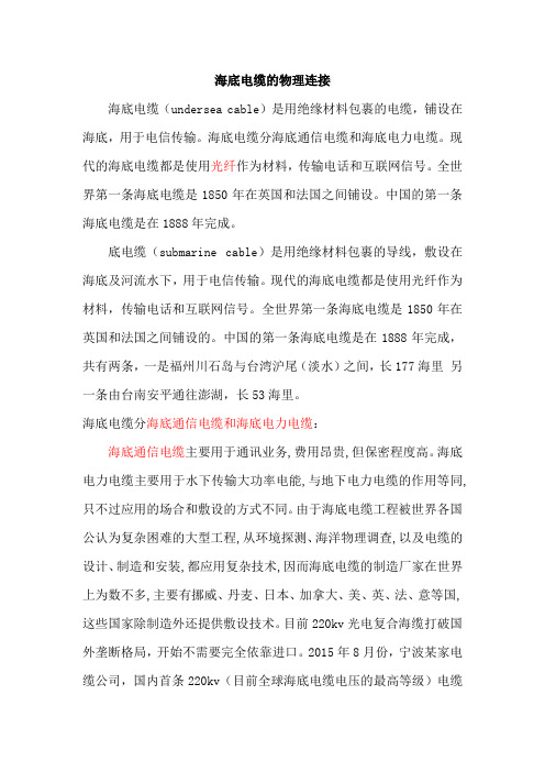
海底电缆的物理连接海底电缆(undersea cable)是用绝缘材料包裹的电缆,铺设在海底,用于电信传输。
海底电缆分海底通信电缆和海底电力电缆。
现代的海底电缆都是使用光纤作为材料,传输电话和互联网信号。
全世界第一条海底电缆是1850年在英国和法国之间铺设。
中国的第一条海底电缆是在1888年完成。
底电缆(submarine cable)是用绝缘材料包裹的导线,敷设在海底及河流水下,用于电信传输。
现代的海底电缆都是使用光纤作为材料,传输电话和互联网信号。
全世界第一条海底电缆是1850年在英国和法国之间铺设的。
中国的第一条海底电缆是在1888年完成,共有两条,一是福州川石岛与台湾沪尾(淡水)之间,长177海里另一条由台南安平通往澎湖,长53海里。
海底电缆分海底通信电缆和海底电力电缆:海底通信电缆主要用于通讯业务,费用昂贵,但保密程度高。
海底电力电缆主要用于水下传输大功率电能,与地下电力电缆的作用等同,只不过应用的场合和敷设的方式不同。
由于海底电缆工程被世界各国公认为复杂困难的大型工程,从环境探测、海洋物理调查,以及电缆的设计、制造和安装,都应用复杂技术,因而海底电缆的制造厂家在世界上为数不多,主要有挪威、丹麦、日本、加拿大、美、英、法、意等国,这些国家除制造外还提供敷设技术。
目前220kv光电复合海缆打破国外垄断格局,开始不需要完全依靠进口。
2015年8月份,宁波某家电缆公司,国内首条220kv(目前全球海底电缆电压的最高等级)电缆开始装船,意味着中国也能够自行研发制造高压电缆,不再依赖国外进口!在海底光缆的制作中,光纤首先会被嵌入在类似果冻的化合物中,保护即使在与海水接触的情况下电缆也不会损坏。
然后将光缆装入钢管中,防止水的压力将其破坏。
接下来将其包裹在整体强度极高的钢丝之中,并套在铜管之中,最后套上聚乙烯材料的保护层。
靠近大陆架的海岸,海底电缆的铺设通常采用轻质电缆搭配强度更大的钢丝,并覆盖沥青涂层以防止海水腐蚀。
海底光缆
海底光缆目录[隐藏]三芯海底光缆Submarine Optical Fiber Cable。
[编辑本段]什么是海底光缆世界各国的网络可以看成是一个大型局域网,海底和陆上光缆将它们连接成为互联网,光缆是Internet 的“中枢神经”,而美国几乎是Internet 的“大脑”。
美国作为Internet 的发源地,存放着很多的Web和IM(如MSN)等服务器,全球解析域名的13个根服务器就有9个在美国,登录多数.com 、.net 网站或发电子邮件,数据几乎都要到美国绕一圈才能到达目的地。
连接“中枢神经”和“大脑”的是海底光缆系统,它分为岸上设备和水下设备两大部分。
岸上设备将语音、图象、数据等通信业务打包传输。
水下设备负责通信信号的处理、发送和接收。
水下设备分为海底光缆、中继器和“分支单元”三部分:海底光缆是其中最重要的也是最脆弱的部分。
海底光缆系统作为一种高质量、低成本、大容量的传输手段日益受到人们的青睐,特别是使用EDFA(掺饵光纤放大器)作为中继器的光直接放大多中继技术,使传输容量从560Mb /s一举提高7倍,已开发了每纤可传输5Gb/s信号的海底光缆系统。
海底光缆是通信用的,一般铺设于深海或者浅海,或者河道,不易于受损敷设在海底的通信光缆,称海底光缆。
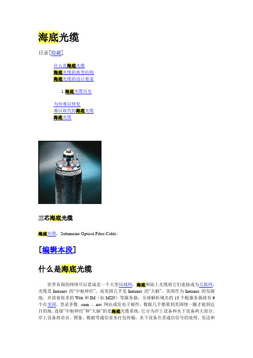
[编辑本段]海底光缆的典型结构海底光缆的结构解析,见右图。
典型海底光缆的结构解析1 聚乙烯层2 聚酯树酯或沥青层3 钢绞线层4 铝制防水层5 聚碳酸酯层6 铜管或铝管7 石蜡,烷烃层8[编辑本段]海底光缆的设计要求海底光缆设计必须保证光纤不受外力和环境影响,其基本要求是:能适应海底压力、磨损、腐蚀、生物等环境;有合适的铠装层防止渔轮拖网、船锚及鲨鱼的伤害;光缆断裂时,尽可能减少海水渗入光缆内的长度;能防止从外部渗透到光缆内的氢气与防止内部产生的氢气;具有一个低电阻的远供电回路;能承受敷设与回收时的张力;使用寿命一般要求在25年以上。
深海(深度在1000米以上)海底光缆采用无钢丝铠装结构,但光缆缆心的结构和加强构件(一般为中心钢丝)必须能保护光纤,以防止海水的高压力与敷设、回收时的高张力。
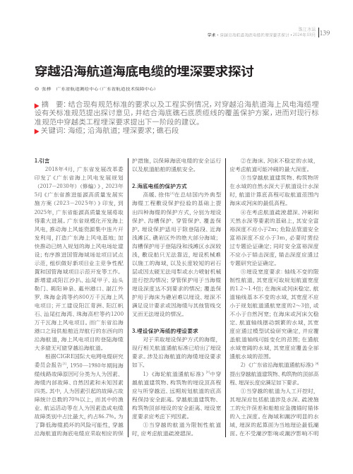
穿越沿海航道海底电缆的埋深要求探讨
1.引言2018年4月,广东省发展改革委印发了《广东省海上风电发展规划(2017-2030年)(修编)》,2023年5月《广东省推进能源高质量发展实施方案(2023-2025年)》印发,到2025年,广东省能源高质量发展将取得重大进展。
广东省规模化开发海上风电,推动海上风能资源集中连片开发利用,打造广东海上风电基地;加快推动已纳入规划的海上风电场址建设;有序推进国管海域场址项目试点示范,组织做好新项目业主竞争性配置和国管海域项目示范开发等工作。
新增建成阳江沙扒、汕尾甲子、汕头勒门、揭阳神泉、惠州港口、湛江外罗、珠海金湾等约800万千瓦海上风电项目;开工建设阳江青洲、阳江帆石、汕尾红海湾、珠海高栏等约1200万千瓦海上风电项目。
而广东省沿海港口之间供船舶近岸航行的东西向的沿海航道,海上风电项目的登陆海缆大多避无可避穿越沿海航道。
根据CIGRE国际大电网电缆研究委员会报告[1],1950—1980年期间海缆线路故障原因可分类为人为因素、海缆内部故障、自然因素和未知因素四类。
其中,人为因素引起的故障占故障统计总数的70%以上,而其中的渔业、航运活动等在人为因素造成电缆故障类别中占比最大,约占86.7%。
为了降低海缆损坏的风险可能性,穿越沿海航道的海底电缆应采取相应的保护措施,以保障海底电缆的安全运行以及航道船舶的通航安全。
2.海底电缆的保护方式高媛、徐伟[2]在总结国内外典型海缆工程敷设保护经验的基础上提出四种海缆的保护方式,分别为埋设保护、沟槽保护、穿管保护、覆盖保护。
埋设保护适用于除登陆段、近海浅滩区、礁岩区外的绝大部分海域;沟槽保护用于登陆段和浅滩区水深较浅,敷设船只无法靠近,埋设机械难以施工的海域,以及长度较短的岩石层或因太硬无法用犁或水力喷射机械进行挖沟情况;穿管保护用于当海缆埋设深度达不到要求的情况;覆盖保护用于海床为礁岩难以埋设、埋深不满足设计要求或因海缆与其他管线交叉而无法埋设的情况。
海上风电场海底电缆路由的调查过程及方法分析

海上风电场海底电缆路由的调查过程及方法分析作者:刘光昊李海波来源:《风能》2014年第03期摘要:以拟建的唐山乐亭菩提岛海上风电场海底电缆路由的调查方案为例,利用浅地层剖面测量、测扫声呐调查和底质沉积物分析,结合浅钻工程地质原位测试的方法,总结出海底电缆路由的敷设所历经详细调查过程,介绍了海底电缆路由的调查勘察技术要求,主要内容和勘察实施方法,并列举了路由区环境综合分析应包含的主要内容,以及提交的成果报告书应包括的主要内容提纲。
关键词:海底电缆;路由;调查;方法中图分类号:TM614 文献标识码:A 文章编号:1674-9219(2014)03-0062-04Analysis of the Investigation Process and Method of Cable Routing in Offshore Wind FarmLiu Guanghao1, Li Haibo2(1. Hebei Construction &Investigation New Energy Co.,Ltd., Shijiazhuang Hebei 050081,China;2. China Suntien Green Energy Co.,Ltd., Shijiazhuang Hebei 050000, China)Abstract: Tis paper takes the investigation process and method of cable routing in Tangshan LeTing bodhi island ofshore wind farm as an example, taking advantage of shallow profle measurement, side scan sonar survey and botom sediment analysis, in consideration of method of shallow drilling engineering geology in situ testing. It also summarizes detailed investigation process of submarine cable route lay and describes the technical requirements of submarine cable route investigation, main content and survey method, enumerated main content of route area comprehensive environmental analysis and main outline of the fnal report.Keywords: submarine cable; route; investigation; method0 引言我国沿海地区,尤其是河北沿海地区风能资源丰富,预计近海可开发量超过4000 MW,且具有较好的海上风电场建设条件,适合大规模开发海上风电。
海上风电场项目海底电缆施工方案
海上风电场项目海底电缆施工方案
1主海缆敷设工艺流程:
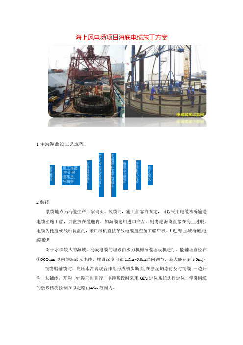
2装缆
装缆地点为海缆生产厂家码头。
装缆时,施工船靠泊固定,可以采用电缆核桥输送电缆至施工船,并盘放在缆舱内。
如海缆选用进口产品,则考虑海缆直接在海上过驳。
电缆为托盘或线轴装盘的,采用吊机直接吊放电缆盘至施工船甲板。
3近海区域海底电缆敷埋
对于水深较大的海域,海底电缆的埋设由水力机械海缆埋设机进行。
能铺埋直径在①30Omm 以内的海底光电缆,埋设深度可在1.5m~6.0m 之间调节,最大能达到6.0m(> 铺缆船铺缆时,高压水冲击联合作用形成初步断面,在淤泥坍塌前及时铺缆,一边开沟一边铺缆,开沟与铺缆同时进行,电缆敷设时采用GPS 定位系统进行定位,牵引钢缆的敷设精度控制在拟定路由±5m 范围内。
涌试蛤收 终端电气安装 海缆冲埋固定 终蜡登升压平台施工 海中段电缆敷埋施工 始端登陆施工 施工准备 (牵引钢 缆布放、 扫海等 装缆运输
4海缆登陆
根据海上风电场2区工程220KV海底电缆路由勘查情况,登陆岸段地形平坦,水深约5m左右,可根据水深情况,海缆敷设船尽可能靠近岸边,起抛锚艇抛锚定位。
用登陆点绞车回卷钢缆,牵引海底电缆至登陆点设定位置。
海缆泡沫浮筒绑扎位置示意图泡沫浮筒Q QO o
海缆登陆示意图泡沫浮筒
海底复合缆。
海上风电场海缆登陆施工方案技术总结

海上风电场海缆登陆施工方案技术总结海上风电场的建设是近年来新能源领域的热门项目,随着风电技术的不断成熟和发展,海上风电场已经成为未来可再生能源的主要发展方向之一。
而海缆登陆施工是海上风电场建设的重要环节之一,其技术总结对于提高施工效率、保障施工质量具有重要的意义。
本文将围绕海缆登陆施工方案的技术总结展开讨论。
一、海缆登陆施工方案概述海缆登陆施工是指将海上风电场的海缆从海上布设区域引入陆地接入系统的过程。
海缆登陆施工方案的制定需要充分考虑海缆的类型、长度、直径、环境条件、施工船只等因素,以制定最优化的施工方案。
海缆登陆施工方案通常包括以下内容:海缆输送船位置安排、海缆安装船动态定位、海缆输送系统、岸线设备、海缆过渡系统等。
1. 海缆输送船位置安排海缆输送船的位置安排对于海缆登陆施工的成功至关重要。
在海缆登陆施工过程中,海缆输送船需要保持稳定的位置,以便顺利进行海缆的输送和安装。
需要在施工前进行精确的海域勘测和动力定位系统的设计,以确保海缆输送船在施工过程中能够保持理想的位置。
2. 海缆安装船动态定位海缆安装船是海缆登陆施工中的核心设备,其动态定位技术对于海缆的安全、稳定输送至关重要。
海缆安装船动态定位技术包括全球卫星导航系统(GNSS)定位、激光测距技术、测深仪等。
在海缆登陆施工中,海缆安装船需要根据海缆输送的动态变化进行实时调整,以确保海缆的安全输送。
3. 海缆输送系统海缆输送系统是海缆登陆施工的关键设备之一,其设计和制造质量直接关系到海缆的安全、稳定输送。
海缆输送系统应具备良好的耐腐蚀性能、高强度和可靠的控制系统,以适应海上恶劣的环境条件。
海缆输送系统的设计应考虑海缆的长度、直径、重量等因素,以确保海缆能够稳定、快速、安全地输送至陆地接入系统。
4. 岸线设备岸线设备是海缆登陆施工的重要组成部分,其设计和制造质量直接关系到海缆的顺利登陆。
岸线设备应具备良好的吸振、导向和固定功能,以确保海缆能够稳定、安全地登陆至陆地接入系统。
- 1、下载文档前请自行甄别文档内容的完整性,平台不提供额外的编辑、内容补充、找答案等附加服务。
- 2、"仅部分预览"的文档,不可在线预览部分如存在完整性等问题,可反馈申请退款(可完整预览的文档不适用该条件!)。
- 3、如文档侵犯您的权益,请联系客服反馈,我们会尽快为您处理(人工客服工作时间:9:00-18:30)。
ENVIRONMENTAL IMPACT ASSESSMENT ORDINANCE (CHAPTER 499)SECTION 5(1)(b)PROJECT PROFILEFORSUBMARINE CABLE LANDING INSTALLATION AT TUEN MUN FOR HGC OPTICAL FIBRE SUBMARINE CABLE SYSTEM BETWEEN TUEN MUN AND CHEK LAP KOKTender No.: T-008-49Issue: August 2000CONTENTSPAGE 1BASIC INFORMATION1.1Project Title 11.2Purpose and Nature of the Project 11.3Name of Project Proponent 11.4Location and Scale of Project (include Plans) and History of Site1.4.1Location of Project 11.4.2Scale of Project 21.4.3History of Site 21.5Number and types of Designated Projects to be covered by the Project Profile 21.6Name and Telephone Number of Contact Person(s) 2 2OUTLINE OF PLANNING AND IMPLEMENTATION PROGRAMME 3 3POSSIBLE IMPACT ON THE ENVIRONMENT 4 4MAJOR ELEMENTS OF THE SURROUNDING ENVIRONMENT4.1Gazetted Beach 4 5ENVIRONMENTAL PROTECTION MEASURES TO BE INCORPORATED IN THE DESIGN AND FURTHER ENVIRONMENTAL IMPLICATIONS5.1Landing Point Construction and Operation 45.2Landing Point Construction and Operation 55.3Landing Point Construction and Operation 5 APPENDICESAppendix 1 - Proposed Cable Route 6Appendix 2 - Proposed Tuen Mun Landing Point TM1 7Appendix 3 - Typical Section of Landing Point 8PROJECT PROFILEFORSUBMARINE CABLE LANDING INSTALLATION AT TUEN MUNFORHGC OPTICAL FIBRE SUBMARINE CABLE SYSTEMBETWEEN TUEN MUN AND CHEK LAP KOK1BASIC INFORMATION1.1Project TitleSubmarine Cable Landing Installation at Tuen Mun for Hutchison Global Crossing Ltd.(HGC) Optical Fibre Submarine Cable System between Tuen Mun and Chek Lap Kok.1.2Purpose and Nature of the ProjectHutchison Global Crossing Limited (HGC) is planning to install a submarine optical fibre network between Tuen Mun and Chek Lap Kok across Chi Shui Men.The purpose of this submarine optical cable project is to connect the HGC's main exchanges at Kwai Chung and Chek Lap Kok through the network along Route 3, Tai Lam Tunnel, Yuen Long, Tuen Mun and Airport. This submarine optical cable provides diversity to the Airport and Lantau Island in case of network contingencies occurred at Tsing Ma Bridge and Northern Lantau Express.The route map of the proposed submarine optical cable is attached as Appendix 1.Based on detailed study and site investigation, it is devised that the submarine optical cable will be landed near the west end of Butterfly Beach, Tuen Mun.The proposed work in this Project Profile involves construction of landing structures at the cable landfalls and laying of submarine optical cables from Tuen Mun to Chek Lap Kok.1.3Name of Project ProponentHutchison Global Crossing Limited (HGC)1.4LOCATION AND SCALE OF PROJECT AND HISTORY OF SITE1.4.1Location of ProjectThe proposed work in this Project Profile involves construction of landing points at Tuen Mun and Chek Lap Kok and associated submarine optical cables landing installation. The landfall at Tuen Mun is located at west of Butterfly Beach.The submarine cable landing point at Tuen Mun TM1, which may be a designated project under the Environmental Impact Assessment Ordinance as detailed in Section 1.5, is shown in Appendix 2.1.4.2Scale of ProjectThe scope of work under this project profile involves the following works at the submarine cable landing point TM1 constructed on a rubble-mounted seawall and seabed extending from it:(a)At land portion:•Construct an underground concrete structure as Armour Clamp Bay to fix submarine cables [Typical size: 2.4m(W) x 2.4m(L) x 2.0m(D)];•Construct an underground concrete manhole for jointing of submarine and land cables [Typical size: 1.6m(W) x 4.0m(L) x 2.5m(D)].(b)At seawall:•Excavate the rubble-mounted seawall to designed level;•Prepare bedding for laying precast cable trough;•Place precast units on top of bedding;•After laying of submarine cables, backfill the precast units;•Restore rubble-mounted seawall to original position.(c)Excavate a short underwater trench (~500m length depending on seabed profile andhardness conditions) at shallow waters near shore;(d)Lay submarine optical cables from a cable laying barge across Chi Shui-Men to theopposite shore at Chek Lap Kok by simultaneously laying and burying method. Thecables will be buried at 3.5m (typical) below seabed.1.4.3History of SiteThe landfall at TM1 is a rubble mounted sea-wall. A similar submarine cable landing point at 300m west of TM1 was constructed by CLP Power Hong Kong Ltd. in 1997.1.5Number and Type of Designated Projects to be covered by the Project ProfileThis Project Profile involves a landing point at Tuen Mun (TM1) which may be classified asa Designated Project under Category C.12(a) (iii) in Schedule 2 (Part 1) of the EIAOrdinance:Schedule 2 (Part 1)C12 A dredging operation which:-(a)is less than 500m from the nearest boundary of an existing:-(iii) bathing beach.1.6Name and Contact Persons and CorrespondencesAll queries regarding the project profile can be addressed to:Manager - External PlantInfrastructure Development DepartmentHutchison Global Crossing Limited2OUTLINE OF PLANNING AND IMPLEMENTATION PROGRAMMEThe project is led by Hutchison Global Crossing Ltd. (HGC). Planning and construction will be undertaken by the following team:•Project Management - Associated Technical Services Ltd.•Civil & E&M Design - Associated Technical Services Ltd.•Landing Point Construction and Submarine Optical Cable System Installation -International Cable Supplier to be appointed.Major project milestones are:Application to Office of Telecom Authority (OFTA)13 Jan 2000Approved in-principle by OFTA31 Jan 2000Application to District Land Office (DLO) for Route Approval 5 Jan 2000Issue of Wayleave of submarine cable route by DLO31 Jan 2001 (tentative) Commencement of Civil Work at Landing Point 1 May 2001Submarine Optical Cable Installation Oct-Dec 2001Optical Cable Commissioning31 Dec 2001All the works at the landing point TM1 are scheduled to be completed in around 8 months within the period May-Dec 2001. Typical sections showing design of landing point is shown in Appendix 3.The major works to be carried out at TM1 are:(a)Part of the rubble-mounted seawall will be temporarily removed. A ramp trench in1:15 cut slope of approximately 50m in length and 5.0m wide will then be formed onthe sea bed by conventional open excavation.(b)Levelling stones will be placed on the trench as bedding. A concrete trough will beinstalled on top of the levelling stones bedding at 1.0m under the seawall to 1.75mbelow ground.(c) A reinforced-concrete structure of typical size of 2.4m (W) x 2.4m (L) x 2.0m (D)will be built as a Armour Clamp Bay for fixing of submarine optical cables. Theheadroom of the clamp bay is 1.55m.(d) A reinforced-concrete structure of typical size of 1.6m (W) x 4.0m (L) x 2.5m (D)will be built as a manhole for jointing submarine and land optical cables. Theheadroom of the manhole is 2.0m.(e) A short underwater trench of approx. 1m (W) x 1m (D) will be excavated bydredging at the shallow water using a small powered backhoe machine on a barge upto ~500m from shore.(f)The cables will be paid out from a cable barge staying at deep water, floated onbuoys and pulled to the landing manhole by a winch installed on land.(g)The optical cables will be protected by Polycon F.R.P. (or equivalent) pipes and thenplaced on the concrete trough. The trough will be covered up with tremie concrete.(h)The optical cables on the sea bed close to the concrete trough will be backfilled/protected by concrete mat (mattress) or rubble of adequate size up to the original seabed level.(i)The optical cables at the landward side will be anchored inside the Armour ClampBay and jointed inside the Manhole to the land cables.(j)The rubble-mounted seawall will be restored to its original state after the completion of cable installation.3POSSIBLE IMPACT ON THE ENVIRONMENT3.1Operation StageThe whole submarine optical cable will be buried. There is no emission of gas, dust and odour during operation. The optical cables consist of stable silicon optical fibres protected by corrosion resistance polyethylene and steel wire armours and are designed for a normal working life-time of 40 years. There is no risk of accidents which would cause pollution.3.2Construction StageThe construction work at shore will only be carried out at day time. The construction noise would not exceed noise limits stipulated in Noise Control Ordinance and subsidiary legislation. Similarly, the dust control measures stipulated under the Air Pollution Control (Construction Dust) Regulation would be applied.For work to be carried out at rubble-mounted seawall, the boulders would be reused for reinstatement. No waste material or disposal would be left causing adverse impact on the environment.For the excavation of underwater trench near seashore, the excavated material will be dumped at designated Mud Disposal Pits arranged by Marine Fill Committee of CED. The near shore trench will be backfilled by concrete mat or boulders which will not contaminate the water.The submarine cable laying and burying operation will not utilize any foreign substances that could contaminate the environment.Impacts of this project to other environmental issues are considered negligible.4MAJOR ELEMENTS OF THE SURROUNDING ENVIRONMENT4.1Gazetted BeachButterfly Beach is a gazetted public bathing beach. Since the landing point TM1 is about 200m from the boundary of the beach which is constructed under control method and also the submarine optical cables are buried, there is no visual impact and inconveniences to the beach users during both construction and operation stages.5ENVIRONMENTAL PROTECTION MEASURES TO BE INCORPORATED IN THE DESIGN AND FURTHER ENVIRONMENTAL IMPLICATIONS5.1Landing Point Construction and OperationThe construction of the cable landing point will take less than 5 months. Potential environmental impacts will be the dust and noise generated during the construction stage which can be controlled by observing the relevant noise and construction dust Regulations.There is no environmental impact during operation stage of the landing point.5.2Submarine CableThe total submarine cable installation work including preparation and cable protection works will take about 3 months but the actual cable laying from one seashore to the opposite seashore would take about 2 weeks time. The residual environmental impacts to the submarine cable laying activities will be localised to the immediate vicinity of the cable alignment, short duration, low severity and acceptable.There is no environmental impact predicted during the operation of the submarine cable.5.3Further ImplicationsThe geotechnical environment around the proposed landing point has been confirmed to be suitable for submarine optical cable landing by electronic surveys. The nearby site has been employed for the landing of 132kV submarine power cables belonging to CLP Power and the cables have been operated for several years without any environmental issues arisen.The above-mentioned construction method is a common method for the installation of submarine optical cable. It has been widely used around the world and is widely accepted to have no impact on the surrounding environment. The working period is normally very short.Also there is no waste disposal issue or no excessive noise will be generated in these operations.- END -。