福克斯波罗浮筒液位计使用说明(英文版)
244LD浮筒液位计标定方法
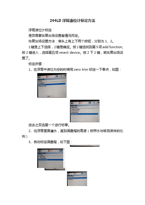
1、在浮筒中液位为空的时候用zபைடு நூலகம்ro trim标定一下零点,如图:
进去之后选第一个进行标零。
2、往浮筒里面灌水,直到满量程的高度(按照水与被测液体的比例)
3、自动标定满量程,如下图:
选择Apply URV,自动进行满量程标定。
在浮筒中液位为空的时候用zerotrim标定一下零点
244LD浮筒液位计标定方法
浮筒液位计标定
是否需要恢复出场设置看情况而定。
恢复出场设置方法:表头上有上下两个按钮,分别为1、2。
1键是上下选择,2键是确定。按1键选找到第5项add.function,按2键进入,选择第五项resect device。按2下2键,就恢复出场设置了。
144LD_2MI_A_001_en
05.2003
MI EML0610 A-(en)
144LD Intelligent Buoyancy Transmitter with Torque Tube and Displacer for Level, Interface and Density with Communication HART / FoxCom
remote amplifier mounting kit
Repair and maintenance must be carried out by qualified personnel!
2
1 2 2.1 2.2 3 3.1 3.2 3.3 3.4 3.5 3.6 4 4.1 4.2 4.3 4.4 4.5 5 5.1 5.2 6 7 8 8.1 8.2 8.3 8.3.1 8.3.2 8.3.3 8.3.4 8.3.5 8.3.6 9 9.1
PAGE
DESIGN . . . . . . . . . . . . . . . . . . . . . . . . . . . . . . 3 MAINTENANCE, REPAIR . . . . . . . . . . . . . . . . 25 Visual inspectiont . . . . . . . . . . . . . . . . . . . . . . . 25 Sensor check. . . . . . . . . . . . . . . . . . . . . . . . . . 25 Amplifier check . . . . . . . . . . . . . . . . . . . . . . . . 25 Replacement of amplifier alectronics or sensor . 26 Replacing displacer . . . . . . . . . . . . . . . . . . . . . 28 Dismantling and Mounting of 10.6 10.8 10.10 10.12 10.14 11 12 13 14 14.1 14.2 14.2.1 14.2.2 14.2.3 14.2.4 14.2.5 Sensor section . . . . . . . . . . . . . . . . . . . . . . . 29 Connecting rod of sensor cell . . . . . . . . . . . . 31 Heat sink . . . . . . . . . . . . . . . . . . . . . . . . . . . 32 Torque tube . . . . . . . . . . . . . . . . . . . . . . . . . 32 Wafer body bearing . . . . . . . . . . . . . . . . . . . 33 DIMENSIONING OF DISPLACER. . . . . . . . . . 34 SAFETY REQUIREMENTS . . . . . . . . . . . . . . 36 DIMENSIONS . . . . . . . . . . . . . . . . . . . . . . . . . 37 SUPPLY OF TRANSMITTER . . . . . . . . . . . . . 38 General . . . . . . . . . . . . . . . . . . . . . . . . . . . . . . 38 Overview of application types . . . . . . . . . . . . . . 38 Supply via power supply unit . . . . . . . . . . . . . . 38 Direct supply . . . . . . . . . . . . . . . . . . . . . . . . . . 38 Communication . . . . . . . . . . . . . . . . . . . . . . . . 39 Operating via I/A-System . . . . . . . . . . . . . . . . . 39 Intrinsically-safe application . . . . . . . . . . . . . . . 39 10.1 10.2 10.3 10.4 10.5
Foxboro 电浮筒液位计

Product Specifications12.2012PSS EML0710G-(en) 244LD Levelstar Intelligent Buoyancy Transmitter forLiquid Level,Interface and Densitywith Torque tube–HART-Version–The intelligent transmitter244LD LevelStar is designed to perform continuous measurements for liquid level,interfa-ce or density of liquids in the process of all industrial applications.The measurement is based on the proven Archime-des buoyancy principle and thus extremely robust and durable.Measuring values can be transferred analog and digi-tal.Digital communication facilitates complete operation and configuration via PC or control system.Despite extre-me temperatures,high process pressure and corrosive liquids,the244LD measures with consistent reliability and high precision.It is approved for installations in contact with explosive atmospheres.The244LD LevelStar combines the abundant experience of FOXBORO ECKARDT with most advanced digital technology.FEATURES•HART Communication,4to20mA •Configuration via FDT-DTM•Multilingual full text graphic LCD•IR communication as a standard•Easy adaptation to the measuring pointwithout calibration at the workshop•Linear or customized characteristic•32point linearisation for volumetric measurement •Backdocumentation of measuring point•Continuous self-diagnostics,Status and diagnostic messages•Configurable safety value•Local display in%,mA or physical units•Process temperature from–196°C to+500°C•Materials for use with aggressive media•Micro sintermetal sensortechnology2244LDPSS EML0710G-(en)PACTware:OperationFDT-DTM:ConfigurationSupply via power supply unit with communication;ExDirect supply with communication;not ExFurter supply circuits see Master Instruction document.PSS EML0710G-(en)244LD3TECHNICAL DATAData refer to the sensor material Type316L(1.4404) Explosion protection certificates must be observed! Input/OutputMeasuring ranges........50mm to50mupper and lower range valuecontinuously adjustable Standard lenghts ofDisplacer(204DE)........350..3000mm,14..120in;further lenghts on request Weight of displacer1)......max.25NMeasuring span..........2...20N contin.adjustable(to1N on request)Span ratioTurn-down..............1:1..1:10(1:20on request) Accuracy2).............±0.2%;increased accuracywith customized adjustment Transfer function.........linear or customized with upto32setpoints Configuration-with FDT-DTM per HART protocol-via2-wire connection4..20mA-via IR communication-with multi-lingual,full graphic LCD display with%,mA, physical units and2from the outside-to-use buttons Load.................R Bmax=(U S–12V)/23mACommunication HART Connection.............Two-wire systemSupply voltage U S3).......>12V+Rb*0.025ARb is the total burden resistor for lines,HART measure-ment resistor and communication.Current sink.............max.24mASignal range............4to20mAOperating range..........3.8to20.5mA(acc.NE43)Critical error alarms in the2-wire Communication..........<3.6mA and>21mA HART Protocol-2-wire................1200Baud,HART compliant -IR communication.......19200Baud Communication Hardware-Handterminal..........HT375/475-PC Software...........WINxx and FDT/DTM1)For measurement of interface or density:weight25N+buoyant force at lowest density2)Accuracy acc.ANSI/ISA-S51.1-19793)Us(max)with explosionproof device<30V,otherwise<42V Operating conditions4)Process temperature......–196°C...+500°C Pressure ratingacc.to DIN............PN16,40,63,100,160,250 acc.to ANSI...........Class150,300,600,900,1500 Ambient temperature5)6)...–40°C...+70°C7) Relative humidity.........up to100% Condensation...........permittedTransportation-storage temperature.......–40°C...+85°C Protection..............IP66(acc.DIN40050) The device can be operated at a class D2location in accordance with DIN IEC654,part1.Operation condition effectsAmbient temperature......–10°C...+70°CZero................<0.1%/10K8)Span...............<0.07%/10KTotal(0.1max.sp.0.07measured value±)%/10K (sp.=measuring span)<-10°C/>+70°C......twice the valueProcess temperature......<0.1%/10K8) Operating pressure.......no influence(vakuum resis-tant)Transitional behaviorDynamic behaviorDamping(90%-time).....0...32sSwitch-on time.........7sStep response(63%-time)with damping0s........250msUpdate rate.............10/sLong term stability........<0.2%/6months at20°C8) Noise suppressionCommon mode voltage...<AC250V effCommon mode rejection..120dBSeries mode rejection....50dB Filter.................Smart Smoothing4)Not with all materials–see Table of Comparison of Materials page65)Ambient temperature must not exceed50°C at measuring modulehousing,when process medium or heating of medium exceed300°C6)–50°C on request7)Display not readable at T<–20°C or T>+70°C8)For max.measuring span4244LD PSS EML0710G-(en)Material,Pressure Rating&Contact Face,Mounting Directionsee Model CodesMaterial Amplifier housing..Aluminum(Alloy No.GD-Al Si12),Polyurethan coatedor Stainless SteelFor Sour Gas applications acc.to NACE Standard MR-0175-95: Wafer body............316L(1.4404)Torque tube...........Hastelloy C or Inconel600 The material of the seal at the Torque tube bearing corre-sponds to the material of the head piece.MountingMounting method.........sandwich mountedacc.to DIN............DN80,DN100acc.to ANSI...........3inch,4inchNote:Always follow the RH or LH version!See the picture below.The device can not be used“upside down”.All inter-nal parts are mounted and calibrated in inverse manner. The conversion can be performed only by the manufacturer or a contractual partner.Otherwise calibration and pressure test are invalid.Weight Transmitter.............see table page7 Displacer...............see table page10Electrical connectionCable entry thread........M20x1.5or1/2-14NPT Cable gland and screwed sealing plug have to be ordered separately under model code BUSG...For equipment in Ex d version,1screwed sealing plug made of stainless steel is included in delivery.Screw terminals..........wire cross-section up to2.5mm²Test sockets............Ø2mm Electromagnetic compatibility EMCOperating conditions......industrial environment Immunity according toEN61326(3/2002)......fulfilledEmission according toEN61326(3/2002)......fulfilledEN55011,May2000,Group1,Class A........fulfilledEN50081-2............fulfilledNAMUR recommendation Ne21Status Aug.1998fulfilled SAFETY REQUIREMENTSCE LabelElectromagnetic compatibility............2004/108/EC fulfilled Explosion protection acc.to ATEX...94/9/ECSafetyAccording to EN61010-1(resp.IEC1010-1)........safety class IIIInternal fuses............none(or not replaceable bycustomer)External fuses...........Limitation of power supplies for fire protection have to be observed due to EN61010-1, appendix F(rsp.IEC1010-1)PSS EML0710G-(en)244LD5Electrical classification ATEX 2)3)intrinsic safe:AID 421II 1/2G EEx d ib/ia IIC/IIB T4/T6PTB 04ATEX 2011X Zone 0AID 421II 2G EEx d ib/ia IIC/IIB T4/T6PTB 04ATEX 2011X Zone 1explosion-proof:AD 432II 1/2G Ex da/db IIB/IIC T4/T6PTB 02ATEX 1025X Zone 0AD 432II 2G Ex da/db IIB/IIC T4/T6PTB 02ATEX 1025XZone 1Zone 2:Manufacturer’s DeclarationFurther certificates see also our website:http://www.foxboro-eckardt.eu/Ex_de_en/allEX_244LD_en_de.html -FM -CSA -NEPSI -Russia-Kasachstan-Approvals for use on sea ships2)With appropriate 3)National6244LD PSS EML0710G-(en) Comparison of MaterialService Limits of wafer body PN250made of(material)Max.operating pressure in bar at temperature in°CTable of Weights1)Values on requestPSS EML0710G-(en)244LD78244LD PSS EML0710G-(en)(continued)PSS EML0710G-(en)244LD9(continued)10244LD PSS EML0710G-(en) Displacer204DETypical Dimensions and Weights for Density RangesΔρ1)1)Δρ=ρ1-ρ2ρ1=density of lower mediumρ2=density of upper medium2)Using displacer material1.4571can cause small devia-tions in diameter,volume and weight.3)For measurement of interface or density,the max.den-sity of the lower medium is1350kg/m³.4)Min.density of the lower mediumIf a Displacer Chamber is used,the difference bet-ween the diameter of the Displacer and the inside diameter of the Displacer Chamber must be at least 10mm.Lengths<350mm and>3000mm,and density ran-ges<100kg/m³and>2000kg/m³on request.AccessoriesFor Displacer Chamber204DC,Flange combination 204FK and Cover Flange Kit204BCF see PSS EML0901,204..Accessories for Buoyancy Transmitter.(continued)Table of versions for dimensions c,d,g see drawing on next pageVersion Form of Sealings DN80/3inch DN100/4inch PN c d g c d gDIN EN 16B1DIN EN1092B2/C/D/F/EDIN EN109214082140160102162 4063100Form L DIN2696160250ANSI 150RF/SG/STANSI B16.514082140160102162 3006009001500150RJFANSI B16.514082140160102174 3001476009001500102162206 300LF/LM/LG/LTANSI B16.514082140160102174 6009001500RF Raised Face RJF Ring Joint Face LF Large Female LM Large Male LG Large Groove LT Large Tongue SG Small Groove ST Small TongueDIMENSIONS244LD up to PN250/Class1500Subject to alterations -reprinting,copying and translation prohibited.Products and publications are normally quo-ted here without reference to existing patents,registered utility models or trademarks.The lack of any such refe-rence does not justify the assumption that a product or symbol is free.FOXBORO ECKARDT GmbH Pragstr.82D-70376Stuttgart Tel.+49(0)711502-0Fax +49(0)711502-597Mail to:salessupport@foxboro-eckardt.de http://www.foxboro-eckardt.euDOKT 556588038~1Product Specifications for Intelligent Transmitters Product Specification:Device:PSS EML0610144LD Intelligent Buoyancy Transmitter for Liquid Level,Interface and Density with Displacer and Torque TubePSS EML0710A 244LD Intelligent Buoyancy Transmitter for Liquid Level,Interface and Density PSS EML0710G with Displacer and Torque Tube (A:TransStar G:LevelStar )PSS EML1610144LVD Intelligent Buoyancy Transmitter for Liquid Level,Interface and Density with DisplacerPSS EML1710244LVP Intelligent Buoyancy Transmitter for Liquid Level,Interface and Density with DisplacerPSS EML0901204xxAccessories for Buoyancy Transmitters PSS EMO0100Accessories for Devices with HART-Protocol。
浮筒液位计作业流程

浮筒液位计作业流程(中英文实用版)Title: Float Level Gauge Operation Procedure1.准备阶段:在开始操作浮筒液位计之前,请确保所有必要的准备工作已经完成。
This involves checking that all necessary preparations have been completed before starting the operation of the float level gauge.2.安装浮筒:首先,将浮筒安装到浮筒液位计的适当位置。
Next, install the float into the appropriate position of the float level gauge.3.连接管道:将浮筒液位计的输出管道连接到相应的控制系统。
Connect the output pipe of the float level gauge to the corresponding control system.4.调试阶段:启动系统,观察浮筒液位计的运行情况,并进行必要的调试。
Start the system, observe the operation of the float level gauge, and make necessary adjustments.5.校准液位计:根据需要调整液位计的液位范围。
Calibrate the level gauge according to the required level range.6.维护和保养:定期进行浮筒液位计的维护和保养,确保其正常运行。
Perform regular maintenance and inspection on the float level gauge to ensure its normal operation.7.安全注意事项:在操作浮筒液位计时,请遵守相关的安全规定,以确保人身和设备的安全。
FLOELINE LU12 13 14手册(新版)

FLOWLINE超声波液位计型号:LU05/12/11/13 使用说明书如果您的产品出现损坏和故障,请与当地经销商联系,并明确以下事项:1.产品型号及出厂编号2.使用人联系电话及姓名3.大致描述故障现象4.大致说明使用状况之后您会收到一份返修通知单,请按通知地址寄出损坏的仪表。
经销商:(中文说明书仅供参考,阅读时,请参照英文说明)技术参数测量范围:LU05: 0.16英尺-4英尺 ( 5cm-1.2m) LU11: 0.16英尺-10英尺 ( 10cm-5.0m) LU12: 0.16英尺-10英尺 ( 5cm-3.0m) LU13: 0.33英尺-25英尺 (10cm-8m) 精度:空气满量程的±0.2% 分辨率:0.125(3mm ) 发射角度:LU05 / LU12 2直径LU13 / 3直径死区:LU05 / LU12 0.16英尺(5cm )LU13 0.33英尺(10cm )LED 指标:电源、标定、诊断状况 存 储 器:断电保存功能 电源电压:14-28VDC 信号输出:4-20mA 、二线制 失效诊断:恢复到22mA 温度范围:-40~+70℃ 压力级别:0~2bar@ 25℃ 外壳级别:NEMA6X(IP67)传感器材料: PVDF (聚偏氟乙烯) 电缆外套材料:PP (聚丙席) 电缆长度:标准10英尺(3m )单独订购:25英尺(7.6m )或50英尺(15.2m ) 安装螺纹:LU05 / LU12 1NPT (1G ) LU13 2NPT (2G ) 安装垫片:氟化橡胶 等 级:普通C E 认证:EN50082-2immunity一:安全注意事项※关于本说明书在安装和使用产品之前,请仔细阅读本说明书,本说明书适宜于超声波液位计:LULU12/LU11/13/14, 阅读本说明书之前,确定您所订购产品的型号。
※用户的安全责任FLOWLINE公司可提供多种液位计供用户选择,所以,您必须根据应用状况选择完全满足要求的仪表,否则仪表可能无法达到使用要求或造成损坏。
电动浮筒液位变送器的原理和调校
电动浮筒液位变送器的原理和调校李宝华摘要:浮力式液位计应用阿基米德原理,包括恒浮力式、变浮力式两大类。
变浮力式主要是浮筒液位计,利用浮筒沉浸在液体里,根据浮筒被浸的程度不同,则浮筒所受的浮力不同,只要检测出浮筒所受浮力的变化,就可知液位的高低。
英维思-福克斯波罗-埃卡(IPS-Foxboro-Eckardt)的144LD型电动浮筒液位变送器性能优异,长期稳定性好,在国内石化装置、大化肥、大化纤上应用较多。
关键词:阿基米德原理;浮力式液位计;浮筒液位变送器;LD144;原理;调校。
引言在流程工业的生产过程中,常常需要测量某些设备(容器)内介质分界面位置,如气体-液体间的液位高度;气体-固体间的料位高度;液体-液体间的界面高度,等等。
这些液位、料位、界面的测量统称为物位测量,最常用的是液位测量。
物位测量一般是测量某一介质的高度或厚度、长度,所用测量单位多为长度单位。
物位测量的方法很多,常见的有:直读式、浮力式、静压式、电气式、声波式、核辐射式等。
其中浮力式液位计是应用最早的物位测量仪表,包括恒浮力式、变浮力式两大类,应用阿基米德原理。
恒浮力式分浮标式与浮球式,都是维持浮力不变,浮标或浮球漂浮在液面上,其位置随着液位高低而变化,当测出浮标的位置时,就能确定液位的高低或发讯报警。
如浮标液位计(浮子钢带式)、浮球液位计或液位开关(浮子杠杆式)、磁翻板液位计(浮子磁耦合式)。
变浮力式液位计主要是浮筒液位计(变送器),利用浮筒沉浸在液体里,根据浮筒被浸的程度不同,则浮筒所受的浮力不同,只要检测出浮筒所受浮力的变化,就可知液位的高低。
阿基米德原理阿基米德原理是物理学中关于力学的一条基本原理:浸在静止流体中的物体受到流体作用的合力大小等于物体排开的流体的重量,这个合力称为浮力。
浮力的大小可用下式计算:F浮= ρ液(气)·g· V排。
F - 浮力ρ- 液体或气体密度g - 重力加速度V - 物体容积(体积)阿基米德原理说明浸在液体里的物体受到向上的浮力作用,浮力的大小等于被该物体排开的液体的重力。
LevelSite 磁性浮球液位计说明书

Level1LevelSite ® Supplemental GuideFeaturesModel LSSMin Typical SystemFigure 12from the liquid; the tank remains sealed from the surrounding environment (See Figure 2). Accidental spills from sight-glass breakage are eliminated.LevelSite® consists of 3 major components: the float housing, a magnetic float, and the rotating flagassembly. The float housing is an engineered pressure vessel which is externally mounted to the tank. The float housing is designed to handle the same temperatures andpressures found in the tank. It is fabricated from a variety of materials, depending on the application. The alloy models are usually polyvinyliden fluoride (PVDF). Other materials are available on request.The float (See Figure 3), is equipped witha permanent ring magnet assembly. Thisassembly rides at the surface of the liquidcontained within the float housing, rising and falling as the liquid in the tank rises and falls.As the float moves up and down, a magnetic flux field maintains continuous contact with the rotating flags mounted on theoutside of the float housing. Flag rotation occurs as the fluxFigure 3Standard Alloy Float has a resolution of 1/2” (12.7 mm). Rotating flags have a square profilewith embedded permanent magnets. The flux field generated by the ring magnet in the float interacts with the flag magnets causing them to rotate as the float moves up and down inside the housing. After the flags rotate to the new position, the embedded magnets lock the flags in place, making the flags less sensitive to vibration (See Figures 4 and 5).LevelSite®’s rotating flags are mounted in a housingfabricated of extruded aluminum or polycarbonate. The assembly is attached to the outside of the float housing with stainless steel clamps. The ends are sealed against dust and moisture. Since the flags are never in contact with the liquid, they never need to be cleaned and they can’t discolor. If the rotating flag assembly is accidentally crushed, there is no danger of a liquid spill.The rotating flag assembly is available in aluminum orpolycarbonate and measures 1.18”(30 mm) and 1.02” (26 mm) wide,respectively (See Figure 6).Figure 5Figure 6Level3LevelSite ® Supplemental GuideGeneral SpecificationsAluminum flags are offered in an anodized finish of red andsilver or painted in red and white. Anodized flags are suitable for service up to 400°F (200°C); painted versions can be subjected to 600°F (316°C). A glass pane protects the flags. The housing is extruded, black anodized aluminum.Polycarbonate flag housings are clear and impact-resistant. They offer 180° visibility of the flags; level can be seen from front and sides (See Figure 5). Housing and flags can withstand temperatures to 250°F (121°C). Standard flag colors are red and white.LevelSite®s are designed according to the unique requirements of each application. Based on information provided by the user regarding operating temperature, pressure, and “normal” specific gravity of the liquid, a float is selected appropriate to the application. Maximum and minimum conditions are evaluated to ensure that the LevelSite® will function not only at the normal condition, but at each extreme. Maximum temperature and pressure are parameters used to design the pressure vessel (float housing).9 can be used as a guide in selecting the ANSI class flanges and materialsappropriate for your temperature and pressure conditions.Barksdale’s LevelSite® is a unique system that can be custom designed for many types of applications, from a stand-alone, no-power-required levelindicator to a fully-integrated electroniccomponent within a process controlsystem. It can be supplied with process connections located for any of the four standard patterns: top/bottom, top/side, side/side, or side/bottom (See Figure 7). For applications where tank-side mounting of the LevelSite is not practical or desired, top mounted versions are available. Liquid interface configurations require three process connections (See Figure 7).Quality and dependability are built into every BarksdaleLevelSite. As a registered ISO 9001 manufacturer, Barksdale meets the most demanding international standards. LevelSite® can be certified to ASME, ANSI, DIN, BSP and other codes.System SpecificationsFigure 7ConfigurationQualityMaterialPressure/temperature performance parameters for LevelSite housing constructed of 316 stainless steel are specified in the chart. Please consult the factory with pressures/temperatures requiring other alloys.MaterialPressure/temperature performance parameters for LevelSite housing constructed of PVC, PP or PVDF are specified in the chart. Please consult the factory with pressures/temperatures requiring other materials.Figure 8Alloy - maximum operating pressure vs.temperature for ANSI classification.Figure 9Engineered plastic - maximum operating pressure vs. temperatureSee Barksdale’s Standard Conditions of Sale • Specifications are subject to modification at any time • Bulletin #L0018-D • 02/08 • ©2008 • Printed in the U.S.A.43211 Fruitland Avenue • Los Angeles, CA 90058 • 800-835-1060 • Fax: 323-589-3463 • LevelSite ® Supplemental GuideOperating InstructionsGeneral InstallationLevelSite®s are measuring instruments and must be properly treated as such. Make sure that all parts are available and the connecting flanges on the tank correspond to those on theindicator. The float and limit switches (if applicable) are enclosed in a separate box. Remove the bottom connection flange (1) of the float chamber and insert the float with the top uppermost. Replace the bottom flange with the gasket, fixing it to the chamber by tightening all the bolts securely. The LevelSite® must be raised slowly and carefully so that the float is not damaged by severe impact.It is essential to ensure that the flanges on the tank are accurately aligned with the flanges on the LevelSite®. Non-alignment of the flanges causes distortion of the float chamber (2) with the possibility that the float (3) will stick. The Levelsite® must always be mounted vertically. Before commissioning, the flags in the flag assembly (4) must be aligned by means of a magnet so that they all show the color white (polycarbonate) or silver (aluminum). NOTE: It is essential for all flange bolts, the vent-plug (5) and the drain-plug (6) to be fully tightened.The electrical limit switches (7) may be attached at any point in the range on the indicator bar by means of a stainless steel clip. Ensure that the stainless steel clips are installed under the flag assembly. The maximum electrical switching capacity is specified on the nameplate of the limit switch (7) and must not be exceeded. IMPORTANT: The operation of the LevelSite® is based on the magnetic field principle. Ferrous strips, clamps, or screws must not be used.LevelSite®s are always application specific. The most important technical data such as pressure and temperature limits are specified accurately on the nameplate (8). However, the sales drawing for the model number referenced on the nameplate is specific and detailed to the application and is the governingspecification document. Before commissioning, a check must be made to ensure that the technical data shown on the nameplate corresponds exactly with the plant requirements. NOTE: Test pressure and test temperature of the plant must NOT exceed the specifications.The transmitter is installed on the side of the LevelSite® housing, utilizing stainless steel clips, with the transmitter’s probe along the housing. The transmitter may be used in addition to a visual indicator (rotating flag assembly) to provide electronic monitoring of fluid level. If the transmitter is used with a flag assembly, it may be necessary to slide the transmitter’s clamps under the flag assembly. The transmitter is supplied with a mark on its probe. This mark must line-up with the centerline of the processMechanical InstallationElectrical InstallationCommissioningconnector on the LevelSite®. If the transmitter’s probe spans the entire measuring range (center-to-center of the process connections), the probe will be marked to show the measuring range. Electrical Connections: Ground the transmitter’shousing if necessary. The cable length may be up to 3 miles. The transmitter is designed to be maintenance-free and is not field-serviceable. If the unit is not operating properly, replace the entire unit. For more information, refer back to “Tank Level Indicating Transmitter”.Tank Level Indicator (TLI) Installation。
depolo lus余氯分析仪操作手册

IM 50.177AC UA (C/9-02)
1.010-42
简介
Depolox3plus分析仪
D+分析仪包括一个与样水流量组连接的电子控制模块,可适用于安装测量自由氯或总 氯探头及可选的 pH 值或氟探头。本系统可保证精确的测量(依照德国 DIN19643 标 准),本分析仪采用水质分析中最新德发展技术在线氯测量单元长期使用稳定且无需 维护。
Depolox3plus分析仪
1.2 自由氯测量单元
测量室:恒电势三电极测量室 精度:0.01 mg/l 或 2%满量程 灵敏度:0.01 mg/l 或 1%满量程 重量性:0.01 mg/l 或 2%满量程 稳定性:± 2%满量程达一个月运行(条件良好状况下) 响应时间:20 秒(当样水进入测量室 20 秒内,90%的余氯改变可反应出) 输出信号:µA 电流 尺寸:260(宽)×350(长)×160(高)(mm) 重量:3.8kg 材料:电极,铂;其它为不锈钢 样水温度:0 ~ 50°C 样水 PH 值:PH4 ~ PH8 电导率:> 280µs/cm 样水水压:0 ~ 15kg/cm2 ~ 4kg/cm2 样水排泄压力:无压 样水流量:33 升/小时 ± 5 升
非常重要的安全事项-----------------------------SP-1,-2, 技术数据--------------------------------------------第一部分 安装--------------------------------------------------第二部分 操作--------------------------------------------------第三部分 维修--------------------------------------------------第四部分 插图--------------------------------------------------第五部分 备件清单--------------------------------------------第六部分 索引--------------------------------------------------第七部分
- 1、下载文档前请自行甄别文档内容的完整性,平台不提供额外的编辑、内容补充、找答案等附加服务。
- 2、"仅部分预览"的文档,不可在线预览部分如存在完整性等问题,可反馈申请退款(可完整预览的文档不适用该条件!)。
- 3、如文档侵犯您的权益,请联系客服反馈,我们会尽快为您处理(人工客服工作时间:9:00-18:30)。
144LD Intelligent Buoyancy Transmitter with Torque Tubeand Displacer for Level,Interface and Density -All versions -These intelligent transmitters are designed to perform measurements for liquid level,interface or density of liquids.The measurement is based on the Archimedes buoyancy principle.Easy remote configuration and supervision with PC is possible.The devices also can be operated conventionally using local keys.The transmitters are approved for use in hazardous areas.The 144LD combines long years of experience by Foxboro Eckardt with the latest digital technique.FEATURES•Communication HART (also 4-20mA),FoxCom,PROFIBUS PA or FOUNDATION Fieldbus •Conventional operation with local keys •Easy adaptation to the measuring point without calibration at the workshop•Back-documentation of measuring point •Continuous self-diagnostics •Configurable safety value•Software lock for local keys and reconfiguration•Local display in %,mA or physical units •Signal noise suppression by Smart Smoothing •Linear or customized characteristic•Process temperature from –196°C to +400°C •Materials for use with aggressive media •Micro sintermetal sensor technology•Separate mounting of sensor and amplifier withremote amplifier mounting kitRepair and maintenance must be carried out by qualified personnel!Master Instruction10.2008MI EML0610E-(en)2144LD MI EML0610E-(en) CONTENTSCHAP.CONTENTS PAGE 1DESIGN (3)2METHOD OF OPERATION (3)2.1Measuring principle (4)2.2Block diagram with PROFIBUS (5)2.3Block diagram with FOUNDATION Fieldbus (5)2.4Block diagram with HART/FoxCom (6)2.5Explanations to Block diagrams (6)3IDENTIFICATION (10)Nameplates4MOUNTING (12)4.1High medium temperatures (12)4.2Mounting on top of the vessel (12)4.3Mounting on the side of the vessel (12)4.4Kit for Remote Mounting (13)4.5Mounting the wafer body (14)4.6Displacer204DE (16)5ELECTRICAL CONNECTION (18)5.1Signal wire connection (18)5.2Ground..............................18CHAP.CONTENTS PAGE 6COMMISSIONING (19)7DECOMMISSIONING (19)8SETTING OF TRANSMITTER (20)8.1Hardware write protection (21)8.2Setting via local keys (21)Setting of Upper and Lower Range Value (22)8.3Setting via Display Keys (23)8.4HART/FoxCom (24)8.5PROFIBUS (30)8.6FOUNDATION Fieldbus (36)9DIMENSIONING OF DISPLACER (42)10SAFETY REQUIREMENTS (43)11DIMENSIONS (44)12SUPPLY OF TRANSMITTER (45)12.2HART/FoxCom (45)12.3PROFIBUS-PA (47)12.4FOUNDATION Fieldbus (47)Further documentation:Master Instruction MI EML0610B-(en)/MI EML1610B-(en)144LD/144LVD Intelligent Buoyancy Transmitters Communication with HART ProtocolMaster Instruction MI EMO0110A-(en)HT991Universal Hand terminal for HART DevicesMaster Instruction MI EMO0120A-(en)ABO991Display and User Interface for HART devicesWPP991Write Protection ProgramMaster Instruction MI EML0610C-(en)/MI EML1610C-(en)144LD/144LVD Intelligent Buoyancy Transmitters Communication with FOXCOM ProtocolHHT Instruction Book3372I/A Series Hand Held TerminalPC10Instruction Book3466Intelligent Transmitter ConfiguratorMI EML0610E-(en)144LD31DESIGN20Amplifier120Sensor housing 121Sensor131Wafer body with heat sink and torque tube 133Transmission lever 134Torque tube 135Clamping lever150Displacer with suspen-sion chainLHVersion for left-hand mountingarranged in inversed manner.120135134133131150121202METHOD OF OPERATIONThe buoyancy force of the displacer 150is transferred via transmission lever 133and torque tube 134to operating rod of the sensor,where it acts on free end of sensor ele-ment 121.Four thin film metal strain gauge elements are sputtered onto sensor element,which change their resistance in the ratio of the tensile or pressure tension.These four thin film metal strain gauge elements are connected as a Wheatstone full bridge supplied from amplifier.The voltage at the diagonal bridge section which is propor-tional to the effective weight is fed to the electronic amplifier as an input signal.This voltage is converted via the electronic amplifier into the 4to 20mA or digital two-wire output signal.The amplifier is supplied by the signal current circuit in two-wire mode.144LD MI EML0610E-(en)MI EML0610E-(en)144LD52.2Block diagram with PROFIBUS2.3Block diagram with FOUNDATIONFieldbus6144LD MI EML0610E-(en) 2.4Block diagram with HART/FoxCom2.5Explanations to Block diagramsSensorThe force sensor is a Wheatstone bridge of four metal straingauge elements and a Ni100resistor for temperature mea-surement.For calibration the sensor is loaded with weights,in order to determine the characteristic of the sensor.The Lower Range Value is determined by a small buoyancyforce(high weight),Upper Range Value by a larger buoyan-cy force(lower weight).Linearization and Temperature compensationof Sensor characteristicThe sensor signal is linearized and temperature-compen-sated by the included sensor temperature.Linearization ta-kes place via the so-called fingerprint data,which are deter-mined during the production for each sensor.In factory thefingerprint data are loaded into the amplifier.Line Frequency Suppression FilterThere is the selection to filter the noise signal50Hz or60Hz.MI EML0610E-(en)144LD7Smart SmoothingIn factory the Smart Smoothing Band is set to0.15%ofsensor range.The Integration Time of the average value isSensor AdjustmentZero and span of force sensor are adjusted in factory.It is possible to calibrate Zero(situation alignment)with theexternal0%key(see8.2).Custom Calibration(not with Foundation Fieldbus)The user has the possibility with this function of calibratingthe transformer according to his conceptions.By giving of alower and upper measured value the transfer characteristicis again adjusted.This custom calibration can be reset toWe only recommend a custom calibration with either lowerplus upper calibration or an exclusive upper calibration.Transfer function/CharacteristicThe characteristics are available linear,root-extracted andcustomized.With"customized"there are32x/y-valuesavailable.Standard with Level is“linear”.8144LD MI EML0610E-(en)Measured Value SettingThe user can define measured value and unit.Setting of Range(not with Foundation Fieldbus)The measuring range is the range between Lower Range Value and Upper Range Value.Lower Range Value is the weight of the displacer.Lower Range Value without elevat-ion is0.With elevation,the value of elevation has to be en-tered.Setting of Output valueThe output value is the measured value between Lower Range Value and Upper Range Value.Value and unit are freely selectable.The replacement value affects the output.Simulate(only FOUNDATION Fieldbus)After setting a flag it is possible to simulate the measured value with a FOUNDATION Fieldbus Configurator. Convert(only FOUNDATION Fieldbus)Lower/Upper Range Value and Lower/Upper Output Value are freely configurable for value and unit.The measuring range is the range between Lower Range Value and Upper Range Value.The output value is the measured value bet-ween Lower Range Value and Upper Range Value.The output value can be root-extracted.One configures which values are set to the output value and the measured value(primary variable PV).There are following configuration possible:OUT/PV=measured valueOUT/PV=OutputOUT/PV=Output,root-extractedThe difference between OUT and PV is:With OUT is an Alarm processing but not with PV.FIELD_VAL is measured value in%.MI EML0610E-(en)144LD9Low Quantity Suppression (not with PROFIBUS)Setting On or Off for low quantity suppression with root-ex-tracted output.With Level,low quantity suppression is al-ways 0.Output characteristic (only with HART /FoxCom)The Output characteristic can be root-extracted.Replacement /Substitute Value (only HART /FoxCom)In case of error output holds last value or gives a configura-ble Replacement value.If the error does not exist any longer,then "last value"and/or replacement value is taken back (automatic or manuell).Multi-drop (only HART)Analog/Digital Output (only FoxCom)With PC20or a Hand Held Terminal it is possible to switch -HART-Amplifier between “analog”and “Multi-drop”-FoxCom-Amplifier between “analog”and “digital”.With HART-mode “Multi-drop”the output has a digital signal,the measured value is modulated to a 4mA DC signal.With FoxCom-mode “digital”the measured value is modula-ted to a 12mA DC signal.PC20Software enables to simulate the measured value and to write output values directly to the output.FilterThe output signal is damped;damping time ist setable from 0to 32sec (90%).Alarm processing (not with HART /FoxCom)The output signal is supervised by lower and upper pre-and main alarm limits and hysteresis.With exceeding of the alarm limits the status of output sig-nal is set to alarm (PROFIBUS see TI EML 0610P or Foun-dation Fieldbus TI EML0610Q).Mode (here:PROFIBUS)With Configurator the block mode can be switched to AUTO,OUT OF SERVICE (O/S)and MAN.In AUTO the block receives the measured values of the sensor and sends it after calculating by configuration to the output.In O/S the block is out of service.This is the case if e.g.new parameters are sent by the Configurator.In MAN the sensor is switched off.The output can be writ-ten directly by the Configurator.Mode (here:FOUNDATION Fieldbus)Each sub block (Ressource block,Transfer block,Function block)has own modes.AUTO is normal operation.In AUTO the block receives a value from input,calculates the new value and stores it to the output.In O/S the block is out of service.This is the case if e.g.new parameters are sent by the Configurator.In MAN the block input is switched off.The output can be written directly by the Configurator.FURTHER INFORMATIONSPROFIBUSProfibus-PA Profile for Process Control Device Communication with Profibus TI EML 06108PFOUNDATION FieldbusFOUNDATION Specification Transducer Block Application ProcessFOUNDATION Specification Function Block Application ProcessCommunication with FF-Fieldbus TI EML 06108Q10144LD MI EML0610E-(en)3IDENTIFICATION(Examples)The transmitter is identified with three labels.The transmit-ter nameplate1shows the Model Code of the transmitter, which clearly describes the device.The certificate data and the Serial No.are entered on the amplifier nameplate3. The TAG bel2with the Tag No.is located under-neath(as an option).Data on the permissible static pressure and the displacer are documented on the adjustment data label7on the sensor housingTransmitter nameplate1Devicespezification,Model CodeID No.for special versionTag bel2Directly fixed or attached.LID09/16Amplifier nameplate3Without/with explosion protectionType of protectionWith explosion protectionWith explosion protection,Type of protection“Explosionproof”FM/CSAAdjustment data label7Matching the displacer:Take care of correct matching of transmitter and displacer while mounting.Each transmitter is calibrated to the respec-tive displacer according to the ordering data in the factory. Each displacer is marked with the TAG No.or,if not known, with the last three digits of serial number of the respective transmitter.If this identification is non-legible,displacer data can be de-termined by measuring and comparison with the data label of transmitter(one label with the adjustment data is located on the inside and another one on the outside of the cover of the sensor housing).Example:Length L:Length of displacer(=measured length)in mmVolume V:0,25·L·d²·π(L and d in cm!)L=Length of displacer=measured lengthd=Diameter of displacerWeight force FG:To be determined by weighing[kg]*)Sensor label8Additional on ex-proof devices.(Example:)Boiler label9Boiler label with nominal pressure,material,permissible pressure and temperature load,serial no.,etc Location of labels:*)Attention!1kg generates a force of9.807N4MOUNTINGThe transmitter is directly built onto the vessel or alternati-vely on a side-mounted displacer chamber(e.g.104DC). During installation,the permissible static pressure and the ambient temperature range must be observed.(see chap.3.6Boiler label).4.1High medium temperaturesThe permissible ambient temperature must be limited for some applications with high medium temperatures:20Amplifier141Blind flange120Sensor housing142Protection cage/tube 131Wafer body146Venting hole140Connecting flange150Displacer104DE If the vessel contains a turbulent liquid a protection cage/ tube should be used.It has a venting hole146above the maximum liquid level.Between the protection cage/tube 142and the displacer150must be a gap of at least5 (10)mm.4.3Mounting on the side of the vessel NOTE:For explosion-proof devices or devices with certification as overfill protection as per WHG and/or VbF,the remarks in the product specifications PSS EML0610A and in the certi-ficates or approvals must be observed.*)Ferrite rings4.5Mounting the wafer body131133153132139140Place the seal 1391)on the connecting flange 140.In-sert displacer in displacer chamber or vessel.Hold wafer body 132above connecting flange.Engage eyelet 132of displacer chain in notch in transmission lever 133and fit wafer body onto connecting flange.131143132142140In orderto make mounting easier,mounting bracket 132is secured with a stud 142to connecting flange 140.It is advisable to preassemble a stud by screwing a nut 143onto thread.Insert this stud through the top of mounting bracket and connecting flange.Screw sufficient number of nuts onto thread and reduced shaft from underneath for the wafer body 131to be firmly in position.1)When using an electrically non-conducting soft gasketing,the wafer body must be grounded,see chap.5.2.144141139140Place seal 1391)on wafer body.Place blind flange 141on wafer body so that holes in blind flange and con-necting flange 140are aligned.Blind flange can be equip-ped with vent plug 144.143132142Leave stud 142in mounting bracket 132and insert re-maining seven studs.Screw on nuts and tighten gently.Unscrew nut 143and pull stud downwards.141143132142140Push stud 142through connecting flange 140,mounting bracket 132and blind flange 141.Screw on nut 143.Tighten nuts of all eight studs cross-wise in several steps to recommended tightening torque.*)Identification Studs GA;A2-70≤M30A2-50>M30Nuts:G;A2-70≤M20A2-50>M20Note:Studs and nuts material depends on material of wafer body and temperature of process medium.These parts are deli-vered by FOXBORO ECKARDT in accordance with the table below unless otherwise specified in the order:4.6Displacer204DEEnsure correct matching of transmitter and displacer while mounting.Each transmitter is calibrated to the respective displacer according to ordering data in the factory.Each displacer is marked with the TAG No.or,if not known,with the last three digits of the serial number of the respective transmitter.The corresponding displacer data(length,volu-me and weight)are specified on the adjustment data labels mounted on the cover of the sensor housing.See also chap.3”Adjustment data label”.Replacing displacerEnter the changed data of displacer on the adjustment label 7(see chapter3).Pressure RatingThe displacer must be designed for the pressure rating of the vessel-however,at least to the operating pressure-and ordered accordingly.Here the maximum possible tem-perature must be taken into consideration.Displacers made of PTFE are made from solid material, and are,therefore,suitable for all pressures1)When used in Zone0,the eyelets must also be welded.Jointed displacer elementsDisplacers of length over3meters(1m for PTFE)are join-ted(multi-section)displacer elements.The displacer ele-ments are screwed together and secured with the wire clip 151to avoid bending or damage during insertion into the vessel.The elements of displacers withØ<13mm are not screwed together;they are secured with hook and eyelet 152.Additional securing is not necessary1).Diameter Diameter>13mm<13mmor PTFEDamping elementIn operating conditions with strong external vibrations -e.g.nearby compressor stations -the damping element (Option -D)shoud be used.It is hooked onto the suspension chain of the displacer in place of 7chain links (105mm).This spring is specially matched to the resonance frequency of the displacer and is made of stainless steel (Mat.No.1.4310,max operating temperature 250°C)or Hastelloy C (max operating tempe-rature 350°C).Use in Zone 0or as overfill protection as per VbF and /or WHG 1)MechanicsDisplacers of more than 3m length must be secured against oscillating when used in Zone 0.When used as overfill protection as per VbF and /or WHG,the displacer must always be installed with guidance.Gui-dance devices over 3m long must also be secured against bending.Potential equalizationWhen used in Zone 0and /or as overfill protection as per VbF,only displacers of metal or PTFE +25%carbon may be used.A potential equalization line must be mounted as an electri-cal bypass of the displacer suspension(s)if the residual dis-placer weight is ≤10N,or if more than 6contact points are present.To avoid the danger of electrostatic ignition,a connection to the transmitter with good conductivity must be ensured.The volume resistance between the lower end of the displa-cer and the ground may not exceed 106Ω.1)Please see corresponding certificates for further detailsNote for displacers with diameters less than 30mm Displacers with diameters <30mm can also be suspended when the wafer body has already been mounted.As an aid to installation,a wire can be pulled through the hole in the eyelet 153.The displacer is lowered through the wafer body with this wire,past the transmission lever and into the displacer chamber or vessel.The eyelet must then be hooked onto the notch 133in the transmission le-ver.Finally remove the wire.Hooking the eyelet onto the notch in the transmission lever5ELECTRICAL CONNECTION5.1Signal wire connectionGuide cable through cable gland38;observe especially the shielding.Check before mounting cable glands if threads are matching, otherwise housing can be damaged.Cable gland38and cover screw39are interchangeable.Connect analog input signal(versions HART/FoxCom) to terminals45(+)and46(–).Connect bus signal(versions PROFIBUS/FOUNDATION F.) to terminals45and46;no polarity has to be observed. The screw terminals are suitable for wire cross sections of 0.3to2.5mm2.The shield of the bus connection is–with conducting cable glands(recommended)directly connected with the housing–with non-conducting cable glands to be laid onto the inner screw termina l47.Note:When connecting the shielded bus connections,the shielding has to be connected on both sides!(on the trans-mitter as well as on the panel side).For selection of the cable see also the recommendation for cable types acc.to IEC1158-2.Transmitters supplied without cable gland,the cable gland used has to conform to possible Ex requirements.This is the user’s responsibility.Actions:–Tighten cover lock24(if provided)and unscrew cover22.–Guide cable through cable gland and connect to terminals45,46and47.–If necessary connect external ground terminal48.–Proper installation of cable gland has to be observed.–Screw cover22and install cover lock24(if provided). Note:For explosion-proof devices follow reference for cable gland and cover screw in document"Safety Instructions140Series"5.2GroundIf connection to ground is necessary(e.g.potential equali-zation,protection of electromagnetic influence),ground ter-minal47or external ground terminal48must be con-nec-ted.When using an electrically non-conducting gasketing,the wafer body must be grounded by wire E with the connec-tion flange.22Connecting compartment cover24Cover lock38Cable gland(permitted cable diameter6to12mm) 39Cover screw45Connection terminal"+"wire cross46Connection terminal"–"section47Ground terminal max.2.5mm2 Test sockets(Ø2mm)integrated in terminal block 48External ground terminal50Overvoltage protection(if present)6COMMISSIONINGIn any case,installation and safety regulations have to be checked prior to commissioning.See document EX EML 0010A:“Safety Operating Instructions”After correct installation and connection to power supply unit,the transmitter is ready for operation:U>12V dc(HART/FoxCom)U>9V dc(PROFIBUS/FOUNDATION Fieldbus)If necessary the configuration of lower range value,upper range value and damping has to be checked.With the analog versions HART/FoxCom an ampmeter can be attached into the output current loop for check. Checking the settingsChecking the lower range value for level measurement For level measurements,the weight F G of the displacer is equal to the weight force F0for the lower range value (LRV).An exception is the measuring range with elevation. The lower range value(LRV)can be checked with a free-hanging displacer and a completely empty vessel. Checking the lower range value for measuring range with elevationThe lower range value(LRV)F0can only be checked by specifying the vessel level corresponding to F0or by speci-fying the weight for F0(workshop task).Checking the lower range value for interface and densityThe lower range value(LRV)F0can be checked with the following methods:–Displacer is completely immersed in the liquid with the lower density–by specifying the weight force for F0with weights(in the workshop)Upper range valueThe upper range value(URV)F100can be checked with the following methods:–by producing the corresponding level,interface or density,provided the specified operating densities are correct.–by specifying the weight force for F100with weights(in the workshop).DampingDamping of8sec is set at factory.If necessary,this value can be checked on devices with an LCD indicator and changed locally.Correction of lower range value,upper range value, dampingSee chapter8,“Setting of Transmitter”.7DECOMMISSIONINGPrior to decommissioning take precautions to avoid distur-bances:–Observe Ex.protection.–Switch off power supply.–Caution with hazardous process media!With toxic or harmful process media,observe relevant safety regulations.Before dismantling the transmitter,the procedure below should be followed:–Depressurize vessel or displacer chamber.–Drain off measuring medium in displacer chamber.–Protect the environment;do not allow measuring sub-stance to escape.Catch and dispose them properly. The procedure for dismantling the transmitter is the reverse of that described for mounting.8SETTING OF TRANSMITTERZero,lower range value,upper range value and damping of the transmitter are set by manufacturer as specified in the order:•Dimensions of displacer:Lenght,density,weight •Setting Lower Range Value by weight F0:without Zero elevation=0;with Zero elevation=Value of elevation•Upper Range Value corresponding to buoyancy force of displacer(see Chap.9)•Output Range and unitTherefore,calibration at start-up is not necessary.In case the order does not include this data,the transmitter is supplied as follows:displacer weight= 1.500kgbuoyancy force= 5.884N(0.600kg)indication=0...100%damping=8sec(90%time) Operating data and displacer data are stored in the trans-mitter according to the order.Configuration becomes necessary if this data deviates from the values stored.The transmitter is designed for a displacer weight force of max.4kg1)and a buoyancy force of2to20N.The lower range value F0must be within the range4kg to2kg(speci-al version0.5kg).Setting via operating push buttonsSetting can be done by means of the push buttons at the transmitter if•the amplifier housing has external push buttons X, see Chap.8.2“Setting via local keys”,or•the display has push buttons D,see Chap.8.3“Setting via Display keys”.1)Attention!1kg generates a force of9.807N Setting via HART Protocol•Setting with PC;Display and User Interface PC20•Setting with Handterminal•Basic calibration with PC20Calibration(necessary if sensor or amplifier are changed)Setting via FOXCOM Protocol•Setting with PC;software PC10/PC20•Setting with FoxCom Hand terminal•I/A Series System IFDC software•Basic calibration with PC Calibration(necessary if sensor or amplifier are changed)Setting via PROFIBUS Protocol•Setting with PC;Display and User Interface PC20Setting via FOUNDATION Fieldbus Protocol •Manufacturer’s Sensor calibration(Fingerprint data,zero,span)•Customer’s settings with standard configurators, as National Instruments Configurator,Honeywell System(DCS),Siemens Delta V(Emerson),ABBMI EML0610E-(en)144LD218.1Hardware write protectionThe write protection prevents the changing of the configura-tion of the transmitter.To enable writing on the transmitter,the jumper J has to be plugged as shown in the figure be-low.(Amplifier electronics,behind LCD indicator)Note:Additional Software Write Protection can be reset/set via PC20Software.HART/FOXCOM:Note:If no jumper is set,the transmitter is write protected.Write protection No write protectionPROFIBUS/FOUNDATION Fieldbus:No write protectionJumper J connects both left pins(as shown)Write protectionJumper J connects both right pins,or jumper is not set8.2Setting via local keysOperation and functions of local keysThe two local keys0%and100%are used to set up zero,lower range value,upper range value and damping.Amplifier housing with local keysAfter shifting the key protection cap A,insert screw driveror pin(Ø<3mm)into hole B and press down to the se-cond pressure point.Both keys have two assigned functions,dependent onlength of pressing time.Damping1)The damping is(electrically)set to8sec by manufacturer.With the local keys damping can be adjusted between0and32sec(90%time2)).The local display shows the current damping value,whenthe key100%is pressed less than3sec.Further acting ofkey100%stepwise sets the damping.After damping selection,confirm by short acting key0%.Zero,Lower range value and Upper range valuesee next page1)Damping is only adjustable with push buttons if local display isprovided.2)63%time with HART devices22144LD MI EML0610E-(en)Setup of lower and upper range valueWorkshop task Equipment:•Power supply DC 24V,30mA•Local display configured with mA 1)resp.%(OUT in %)or multimeter 1)•Screw driver (Ø<3mm)•Set of standard weights,class M12)•Weighing pan 3)to be suspended in place of displacer Actions:–Put transmitter in operational position and connecttransmitter Setting Zero (not with FoxCom)Zero point is factory-set.If the zero point shifted by another installation position,it can be corrected as follows:–Put on weights for Zero point (2.5kg)–Press key 0%less than 3sec.With HART the output signal is set to 0(4mA).Setting Lower range value–Put on weights for lower range value (F 0)3)–Press key 0%more than 5sec–Measuring span remains unchanged –Indicator displays Lower range valueWith HART the output current is adjusted to 4mA.Setting Upper range value–Put on weights for upper range value (F 100)3)–Press key 100%more than 5sec–Lower range value remains unchanged –Indicator displays Upper range valueWith HART the output current is adjusted to 20mA.Wet calibrationIf process conditions for lower range value and upper range value can be set during installation it is possible to calibrate installed transmitter.Equipment:•Local display configured with mA 1)resp.%(OUT in %)or multimeter 1)•Screw driver (Ø<3mm)Actions:–Set conditions (e.g.level)for lower range value.–Press key 0%more than 5sec.–Set conditions (e.g.level)for upper range value.–Press key 100%more than 5sec."Warm-up"before calibrationTo keep the measuring error at extremely high (or extremely low)process temperatures minimal,it is recommended to have the transmitter reach first the operating temperature.。