Solidworks机械设计说明书
SolidWorks 分析指南:机械设计师的关键性能问题解决方案说明书
w h i t e p A p e R Analysis Guide for Machine DesignersintroductionAnalysis and simulation software is an indispensable tool in the developmentof large-scale machinery. These tools allow the developer to evaluate designsearly in the design cycle, determine causes of premature failures in the field,quickly explore design changes aimed at reducing cost and weight, and deter-mine the product’s factor of safety. Use of analysis tools is of particular valueto machine designers due to the size and complexity of the systems they aredeveloping. Analysis tools can identify design issues that may elude a design-er’s review simply because of the dynamic nature of machinery’s many movingparts.Analysis tools can identify designissues that may elude a designer’sreview simply because of the dy-namic nature of machinery’s manymoving parts.FIGure 1:INNer ArM OF rOBOT DeSIGNeD BY FANuC rOBOTICSThe unyielding demands upon machinery manufacturers by customers andthe market to create systems that are cheaper, more reliable, and more pro-ductive necessitate that companies that wish to remain successful utilize allthe tools available to them. These analysis tools reduce product developmentcosts through a reduction of late engineering changes. They ensure productsreach the market promptly, allowing the product to capture the largest pieceof the market possible. Finally, it allows engineers to experiment with materialsand designs that can result in products of minimal weight and cost. Analysissoftware enables engineers to simulate design performance and identify andaddress potential design problems before prototyping and production.Analysis at the forefront of machine design product developmentRegardless of the specific application, machine designers are under pressurefrom their customers: increase reliability and longevity; be quicker to marketwith new, improved products; reduce product weight and cost; and increaseproductivity. Working in this type of environment, engineers have little time toproduce multiple prototypes and use trial and error to gain a better understand-ing of the physical behavior of their designs. Yet, that information is vital forproducing innovative, high-quality products.FIGure 2:FANuC rOBOTICS TAKeS FuLL ADVANTAGe OF THe SOLID MODeLer INSOLIDWOrKS SIMuLATION.Analysis tools help machine designers understand the physical behavior of their designs quickly without resorting to expensive prototypes and physical tests that extend the product design cycle. Analysis tools can substantially reduce the number of ecos, missed deadlines due to redesigns late in thedesign cycle, and costly redesigns at manufacturing time. All of these markedly decrease development costs and time-to-market. Further, these tools increase communication between design, sales, marketing, manufacturing, and the cus-tomer through their easy-to-read and -understand graphical results.Application areas• Production equipment: hallmark cards, food production• industrial Robots and Robotic systems: design optimization, failure analysis • industrial Food Machinery• Packaging equipment• electromechanical systems: heating• Printed circuit Boards: semiconductors, heat sinks, MeMs• cooling systems: fans, motors, air flows• electronic systems: antennas, transmitters, switches• Automation Tooling• Aerating Machines, for beverages• Bag opening, Filling, and closing Machines• Bottling Machinery: washing, sterilizing, filling, capping, and labeling• Bread-wrapping Machines• carton-packing Machines• label Moisteners, industrial type• labeling Machinery, industrial type• Wrapping MachinesAnalysis tools help machine design-ers understand the physical behaviorof their designs quickly withoutresorting to expensive prototypesand physical tests that extend the product design cycle.Scope of analysis• design verification/validation: Will this design work? Will this design behave the way i think it will?• Relative merit: Which of these candidate designs is the best? how can i weed out and eliminate poor-functioning designs?• Proof of concept: Testing radical new concepts without producing prototypes • durability and reliability: Fatigue/failure analysis, drop tests, shake simulationstight integration with 3D CAD The solidWorks 3d cAd system, the standard for 3d design, is tightly inte-grated with all major cAd software. This means that engineers can use solidWorks analysis software directly on the cAd model and do not needto remodel designs to take advantage of analysis technology.FIGure 3:HALLMArK CArDS DeSIGNS CArD-MANuFACTurING MACHINerY uSING SOLIDWOrKS SIMuLATION.“what if” studiesA clear advantage of performing “virtual” testing using computer simulations over physical testing, beyond the cost and time savings, is the ability to quickly compare many designs incorporating different materials, part geometries, assembly configurations, subsystems, and more. Using analysis to conduct “what if” studies—what if i tried this material, or what if i used this type of mechanism—can help engineers identify the best material and mechanical design for a particular function. Using computational model and analysis soft-ware to perform “what if” evaluations saves time and money and can help to improve design performance. By coupling analysis studies with solidWorks configuration Management, the designer can quickly converge on the best-form design solution over many degrees of freedom.Using computational model andanalysis software to perform “whatif” evaluations saves time and moneyand can help to improve design performance.companies that use analysis to address these issues at the design state develop a clear advantage over their competitors.FIGure 4:MODuLAr AND CuSTOM AIr HANDLerS Are IDeAL prODuCTS FOr ANALYSIS BeCAuSe THeY MuST Be ABLe TO HeAT, COOL, HuMIDIFY, AND DeHuMIDIFY AIr AS WeLL AS FILTer pArTICLeS.powerful analysis types—static, motion, thermal, vibration,fluid-flow, nonlinearMachine designers must work with systems of amazing complexity and vari-ability. The kinematics and dynamics of all of the system’s moving partsand their potential for interference requires a great amount of design effort. Thermal effects of the heat-producing components upon the rest of the systems can be difficult to predict and design around. Vibration and other structural issues can lead to part failures, poor performance, and other opera-tional issues. companies that use analysis to address these issues at the design state develop a clear advantage over their competitors. solidWorks analysis software helps to ensure that these considerations are addressed early in the product development cycle, enabling manufacturers to accelerate time-to-market and reduce development costs while producing higher-quality products with fewer warranty issues. Using a range of analysis technologies, solidWorks software helps engineers to ensure that a product’s behavior will be within design limits, reliable, and free of the risk of thermal, electromag-netic, or stress-induced failures.FIGure 5:CALCuLATING THe CrITICAL FOrCeS OF A rOLLer ON A SHeeTer HeAD TAKeSJuST MINuTeS FOr CASA HerrerA.• static analysis is a tool that empowers the machine designer to avoid cata-strophic immediate or long-term failure modes and determine if redesign of one or more of the core elements is necessary. designers can study the stresses or deflections in the device and compare it against allowable lev-els to predict failure. solidWorks simulation has the ability to analyze shells using solidWorks surfaces and by extracting mid surfaces of thin-walled structures, particularly useful in machines that incorporate sheet metal i n their designs. Through static analysis, designers can optimize geometries, minimize weight and material usage, and determine the factor of safety built into each of their machines.• Motion analysis is also extremely valuable in the development of machinery in that they are by their nature extremely complex, dynamic assemblies. Running motion analysis allows designers to perform “virtual testing” before manufac-turing physical prototypes, saving time and money during the iterative designcycle. changes prior to “cutting metal” are far cheaper and quicker to enact. Motion analysis allows the designer to learn more about the machinery in the concept phase and perform dynamic interference detection prior to building engineering models.• Thermal analysis is critically important in machine design. Managing tempera-ture, whether it’s of printed circuit boards, mechanical devices, or of fluidic systems can be an important design challenge that an engineer must over-come. solidWorks simulation analysis software can perform steady-state or transient thermal analysis on parts or assemblies. After meshing the design, the designer sets any relevant constraints, then sets power or heat flux condi-tions associated with a geometrical feature of the model. Because compo-nent material properties include thermal conductivity, coefficient of thermal expansion, and heat capacity, the designer gets a realistic prediction of tem-perature distributions under prescribed loads and operating conditions.FIGure 6:eND-OF-ArM AuTOMATION TOOLING DeSIGNeD BY puSHCOrp, INC.• Vibration analysis is valuable in many types of machinery products. Many have motors, pumps, and other vibration sources that can adversely affect performance of surrounding electronic and mechanical devices. optimal per-formance, with a minimal amount of adverse effects on these components, requires an understanding of the natural frequencies at which a component or assembly will vibrate and the impact of any stresses or deflections thatUsing solidWorks simulationanalysis software, an engineer cansimulate the natural frequencies of a part or assembly.may occur. Using solidWorks simulation analysis software, an engineer can simulate the natural frequencies of a part or assembly and use this informa-tion to modify the design or materials used to avoid resonance and deflection in certain areas or improve performance. Random vibration analysis can also help engineers stiffen electrical systems that are designed to survive earth-quakes and represent a more cost-effective approach than conducting physi-cal shake tests. Analysis can be used to minimize frequency and vibration to minimize the perturbations’ effects on the system performance.FIGure 7:NeuMAG IMprOVeS NOZZLe DeSIGN WITH SOLIDWOrKS FLOW SIMuLATION.• Fluid-flow analysis has a number of applications in the machine designdomain. Fluid-flow properties play a large role in heat transfer analysis. large machinery generally has large heat sources such as power supplies and motors that require active cooling. convective and conjugative heat transfer are dependent on fluid-flow properties. Fluidic systems such as hydraulics can also be modeled and their designs evaluated. Third, this analysis can be used in the design process of fluidic components such as nozzles, valvings, pump systems, and lubrication systems. Whatever a manufacturer’s analytical needs, solidWorks Flow simulation offers high-powered computational flow dynamics (cFd) analysis for understanding the impact of fluid flow on tem-perature in electrical systems.• nonlinear analysis gives electronics and electrical product designers the ability to evaluate product performance within a complex, 3d-simulated environment, giving them a far more accurate determination of the different factors that may cause a device to fail. nonlinear analysis tools are effective for analyzing static and dynamic problems with geometric and material nonlinearity, hyper-elasticity, creep, thermo-plasticity, and viscoelasticity. solidWorks simulation Premium nonlinear analysis software can also analyze nonlinear contact prob-lems involving surface interactions of models with or without friction.FIGure 8:CYCLONIC INerTIAL SepArATOr BY DAVID rACHeLS AND HIS eNGINeerING TeAMlarge machinery generally has largeheat sources such as power supplies and motors that require active cooling.Assembly analysislarge-scale assembly analysis is absolutely critical for machinery designers. industrial machinery by its nature contains many complex subassemblies of many parts. As such, analysis on machine designs requires a wide range ofattachment, interconnection, and encapsulation methods. designers require that analysis run on their parts, subassemblies, and full assemblies. These assem-blies can be affected by heat, pressure, vibration, impacts, and electromagnetic fields at all levels of the design.FIGure 9:CHuCK DeSIGNeD BY SpeeDGrIp CHuCK INC.solidWorks simulation analysis software enables engineers to simulate all of these behaviors by allowing for the analysis of small or large cAd assemblies. The software allows engineers to assign different materials to different parts of the assembly and specify how the components will interact with each other. solidWorks simulation assembly gap/contact analysis allows you to simulate various real-life conditions for large machines.Many of what in the past have been physical tests on large machines can now be moved to computer simulations. drop tests, to ensure that shipping does not damage the machinery, can be performed during the design phase and easier, less costly changes can be made prior to physical prototyping and manufactur-ing. Thermal analysis can ensure that no components within the system become overheated and can aid in designing appropriate heating and cooling systems within the machinery. sources of vibration within a system can be modeled and their effects on surrounding components studied. This allows for effective isola-tion systems to be developed early in the design cycle.3D VisualizationsolidWorks simulation analysis tools enable analysis of machinery and large-scale industrial products at the component, assembly, and system levels.• 3d visualization provides a designer with a first check of design intent, proper operation, and aesthetics as the project develops.• 3d cAd enables the designer to view a product design from all angles and examine the internal parts of the product throughout the design process. This gives designers a clear and accurate review of parts and assemblies early in the design cycle.solidWorks simulation assemblygap/contact analysis allows you tosimulate various real-life conditions for large machines.• 3d visualization reduces communication and fabrication errors, saving development time by more effectively conveying design information so that designers can find problems early in the design cycle.• designers can view the product from all sides and look inside by hiding the outer enclosure or other parts.• 3d animations of simulations allow you to see how the machinery functions in the real world.• section plots allow you to see simulation results inside the part and not just on the surface.FiGURe 10:The Johnson coRPoRATion desiGns sYsTeMs FoR PRocess indUsTRies.Design communication and collaboration tools• design collaboration has become an increasingly important part of the product development process, enabling designers to share designs easily with anyone, anywhere.• collaboration tools offer new ways for product designers to work more effectively with other members of the development team. The ability to share design resources over the internet benefits all product designers, from inde-pendent consultants to engineers in large multinational corporations.• solidWorks simulation analysis tools allow designers to share analysis results in various formats such as:- hTMl reports of analysis results- VRMl files- AVi files- solidWorks simulation allows users to publish solidWorks edrawings ®files for analysis results.collaboration tools offer new waysfor product designers to work moreeffectively with other members of the development team.ConclusionMachinery manufacturers face relentless demands by customers and the market to create systems that are cheaper, more reliable, and more produc-tive. companies that wish to remain successful utilize all the tools available to them. With analysis and simulation tools, the developer can evaluate designs early in the design cycle, determine causes of premature failures in the field, quickly explore designs changes aimed at reducing cost and weight, and deter-mine the product’s factor of safety. Analysis tools are particularly valuable to machine designers due to the size and complexity of the systems they are developing. solidWorks simulation and analysis tools reduce product develop-ment costs, ensure products reach the market promptly, and allow engineers to experiment with materials and designs that can result in products of minimal weight and cost.。
solidworks使用手册
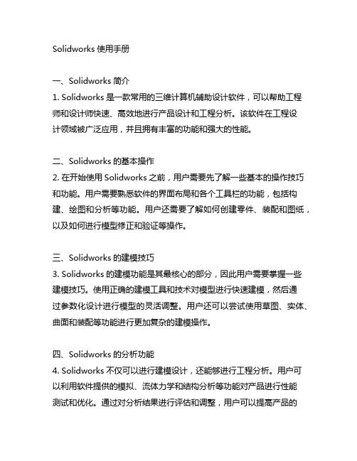
Solidworks使用手册一、Solidworks简介1. Solidworks是一款常用的三维计算机辅助设计软件,可以帮助工程师和设计师快速、高效地进行产品设计和工程分析。
该软件在工程设计领域被广泛应用,并且拥有丰富的功能和强大的性能。
二、Solidworks的基本操作2. 在开始使用Solidworks之前,用户需要先了解一些基本的操作技巧和功能。
用户需要熟悉软件的界面布局和各个工具栏的功能,包括构建、绘图和分析等功能。
用户还需要了解如何创建零件、装配和图纸,以及如何进行模型修正和验证等操作。
三、Solidworks的建模技巧3. Solidworks的建模功能是其最核心的部分,因此用户需要掌握一些建模技巧。
使用正确的建模工具和技术对模型进行快速建模,然后通过参数化设计进行模型的灵活调整。
用户还可以尝试使用草图、实体、曲面和装配等功能进行更加复杂的建模操作。
四、Solidworks的分析功能4. Solidworks不仅可以进行建模设计,还能够进行工程分析。
用户可以利用软件提供的模拟、流体力学和结构分析等功能对产品进行性能测试和优化。
通过对分析结果进行评估和调整,用户可以提高产品的设计质量和性能。
五、Solidworks的图形表达5. 在使用Solidworks进行建模和分析之后,用户需要进行图形表达和文档输出。
软件提供了丰富的绘图和注释工具,用户可以根据需要制作详细的工程图、剖面图和装配图,并且支持各种文件格式的导出和打印。
六、Solidworks的进阶应用6. 对于熟练掌握Solidworks基本操作的用户来说,他们还可以尝试一些高级的应用技巧。
使用宏进行自动化设计,利用云评台进行协作设计和数据管理,以及运用Solidworks API进行二次开发等。
七、Solidworks的学习资源7. 为帮助用户更好地学习和应用Solidworks,软件冠方提供了丰富的学习资源,包括培训课程、视瓶教程和上线交流社区。
SOLIDWORKS 设计图纸 - ISO说明书

SOLIDWORKS SOLIDWORKS Drawings - ISODassault Systèmes SolidWorks Corporation175 Wyman StreetWaltham, MA 02451 U.S.A.© 1995-2022, Dassault Systemes SolidWorks Corporation, a Dassault Systèmes SE company, 175 Wyman Street, Waltham, Mass. 02451 USA. All Rights Reserved.The information and the software discussed in this document are subject to change without notice and are not commitments by Dassault Systemes SolidWorks Corporation (DS SolidWorks).No material may be reproduced or transmitted in any form or by any means, electronically or manually, for any purpose without the express written permission of DS SolidWorks.The software discussed in this document is furnished under a license and may be used or copied only in accordance with the terms of the license. All warranties given by DS SolidWorks as to the software and documentation are set forth in the license agreement, and nothing stated in, or implied by, this document or its contents shall be considered or deemed a modification or amendment of any terms, including warranties, in the license agreement.For a full list of the patents, trademarks, and third-party software contained in this release, please go to the Legal Notices in the SOLIDWORKS documentation.Restricted RightsThis clause applies to all acquisitions of Dassault Systèmes Offerings by or for the United States federal government, or by any prime contractor or subcontractor (at any tier) under any contract, grant, cooperative agreement or other activity with the federal government. The software, documentation and any other technical data provided hereunder is commercial in nature and developed solely at private expense. The Software is delivered as "Commercial Computer Software" as defined in DFARS 252.227-7014 (June 1995) or as a "Commercial Item" as defined in FAR 2.101(a) and as such is provided with only such rights as are provided in Dassault Systèmes standard commercial end user license agreement. Technical data is provided with limited rights only as provided in DFAR 252.227-7015 (Nov. 1995) or FAR 52.227-14 (June 1987), whichever is applicable. The terms and conditions of the Dassault Systèmes standard commercial end user license agreement shall pertain to the United States government's use and disclosure of this software, and shall supersede any conflicting contractual terms and conditions. If the DS standard commercial license fails to meet the United States government's needs or is inconsistent in any respect with United States Federal law, the United States government agrees to return this software, unused, to DS. The following additional statement applies only to acquisitions governed by DFARS Subpart 227.4 (October 1988): "Restricted Rights - use, duplication and disclosure by the Government is subject to restrictions as set forth in subparagraph (c)(l)(ii) of the Rights in Technical Data and Computer Software clause at DFARS 252-227-7013 (Oct. 1988)."In the event that you receive a request from any agency of the U.S. Government to provide Software with rights beyond those set forth above, you will notify DS SolidWorks of the scope of the request and DS SolidWorks will have five (5) business days to, in its sole discretion, accept or reject such request. Contractor/ Manufacturer: Dassault Systemes SolidWorks Corporation, 175 Wyman Street, Waltham, Massachusetts 02451 USA.Document Number: PMT2301-ENGContents IntroductionAbout This Course . . . . . . . . . . . . . . . . . . . . . . . . . . . . . . . . . . . . . . . . 2Prerequisites . . . . . . . . . . . . . . . . . . . . . . . . . . . . . . . . . . . . . . . . . . 2Using this Book . . . . . . . . . . . . . . . . . . . . . . . . . . . . . . . . . . . . . . . . . . 2About the Training Files. . . . . . . . . . . . . . . . . . . . . . . . . . . . . . . . . . . . 3Training Templates. . . . . . . . . . . . . . . . . . . . . . . . . . . . . . . . . . . . . 3Accessing Training Templates in SOLIDWORKS . . . . . . . . . . . . 3Conventions Used in this Book . . . . . . . . . . . . . . . . . . . . . . . . . . . . . . 4Windows OS. . . . . . . . . . . . . . . . . . . . . . . . . . . . . . . . . . . . . . . . . . . . . 5Use of Color . . . . . . . . . . . . . . . . . . . . . . . . . . . . . . . . . . . . . . . . . . . . . 5More SOLIDWORKS Training Resources. . . . . . . . . . . . . . . . . . . . . . 5Local User Groups . . . . . . . . . . . . . . . . . . . . . . . . . . . . . . . . . . . . . 5 Lesson 1:Review of the BasicsReview of Essentials. . . . . . . . . . . . . . . . . . . . . . . . . . . . . . . . . . . . . . . 8Drawing System Options . . . . . . . . . . . . . . . . . . . . . . . . . . . . . . . . . . . 9Beginning a New Drawing. . . . . . . . . . . . . . . . . . . . . . . . . . . . . . . . . 10View Palette and Model Views. . . . . . . . . . . . . . . . . . . . . . . . . . . . . . 11Detailing Techniques . . . . . . . . . . . . . . . . . . . . . . . . . . . . . . . . . . . . . 11Importing Design Annotations . . . . . . . . . . . . . . . . . . . . . . . . . . . 12Using Model Items . . . . . . . . . . . . . . . . . . . . . . . . . . . . . . . . . . . . 13Dimensions in Drawings. . . . . . . . . . . . . . . . . . . . . . . . . . . . . . . . 15Section Views . . . . . . . . . . . . . . . . . . . . . . . . . . . . . . . . . . . . . . . . . . . 18Detail Views . . . . . . . . . . . . . . . . . . . . . . . . . . . . . . . . . . . . . . . . . . . . 20Moving Drawing Views . . . . . . . . . . . . . . . . . . . . . . . . . . . . . . . . . . . 21View Alignment . . . . . . . . . . . . . . . . . . . . . . . . . . . . . . . . . . . . . . 21Moving Dimensions . . . . . . . . . . . . . . . . . . . . . . . . . . . . . . . . . . . . . . 22iContents SOLIDWORKSii Center Marks & Centerlines. . . . . . . . . . . . . . . . . . . . . . . . . . . . . . . . 22 Assembly Drawing Review . . . . . . . . . . . . . . . . . . . . . . . . . . . . . . . . 25 Bill of Materials Tables . . . . . . . . . . . . . . . . . . . . . . . . . . . . . . . . 26 Adding Balloons. . . . . . . . . . . . . . . . . . . . . . . . . . . . . . . . . . . . . . 31 Adding Sheets. . . . . . . . . . . . . . . . . . . . . . . . . . . . . . . . . . . . . . . . . . . 32 Standard 3 View . . . . . . . . . . . . . . . . . . . . . . . . . . . . . . . . . . . . . . . . . 32 Exercise 1: Simple Part. . . . . . . . . . . . . . . . . . . . . . . . . . . . . . . . . . . . 34 Exercise 2: Drawing Views . . . . . . . . . . . . . . . . . . . . . . . . . . . . . . . . 40 Exercise 3: Section Cutting Line Options. . . . . . . . . . . . . . . . . . . . . . 48 Exercise 4: Removed Section Views . . . . . . . . . . . . . . . . . . . . . . . . . 57 Exercise 5: Assembly Practice . . . . . . . . . . . . . . . . . . . . . . . . . . . . . . 59 Exercise 6: Adding Annotations. . . . . . . . . . . . . . . . . . . . . . . . . . . . . 68Lesson 2:Understanding Drawing TemplatesStructure of a Drawing Document . . . . . . . . . . . . . . . . . . . . . . . . . . . 78Drawing Document. . . . . . . . . . . . . . . . . . . . . . . . . . . . . . . . . . . . . . . 78Drawing Sheet. . . . . . . . . . . . . . . . . . . . . . . . . . . . . . . . . . . . . . . . . . . 79Sheet Properties . . . . . . . . . . . . . . . . . . . . . . . . . . . . . . . . . . . . . . 79Sheet Format. . . . . . . . . . . . . . . . . . . . . . . . . . . . . . . . . . . . . . . . . . . . 80Edit Sheet Format. . . . . . . . . . . . . . . . . . . . . . . . . . . . . . . . . . . . . 80Understanding Drawing Templates. . . . . . . . . . . . . . . . . . . . . . . . . . . 80Why are Drawings Structured this Way?. . . . . . . . . . . . . . . . . . . 81Sheet Format Features . . . . . . . . . . . . . . . . . . . . . . . . . . . . . . . . . 83Notes Linked to Properties. . . . . . . . . . . . . . . . . . . . . . . . . . . . . . 84Annotation Link Errors. . . . . . . . . . . . . . . . . . . . . . . . . . . . . . . . . 86Drawing Template Design Strategy . . . . . . . . . . . . . . . . . . . . . . . . . . 88Designing a Drawing Template . . . . . . . . . . . . . . . . . . . . . . . . . . . . . 90Understanding Document Properties . . . . . . . . . . . . . . . . . . . . . . 91Display Settings in Templates . . . . . . . . . . . . . . . . . . . . . . . . . . . 94Sheet Properties in Templates. . . . . . . . . . . . . . . . . . . . . . . . . . . . 95Custom Properties in Templates. . . . . . . . . . . . . . . . . . . . . . . . . . 96Save as Template . . . . . . . . . . . . . . . . . . . . . . . . . . . . . . . . . . . . . 97Defining Template Locations. . . . . . . . . . . . . . . . . . . . . . . . . . . . 98Model Templates . . . . . . . . . . . . . . . . . . . . . . . . . . . . . . . . . . . . 100Creating a Sample Model and Drawing . . . . . . . . . . . . . . . . . . . . . . 101Exercise 7: Defining Units . . . . . . . . . . . . . . . . . . . . . . . . . . . . . . . . 104Exercise 8: Designing Model Templates . . . . . . . . . . . . . . . . . . . . . 108Exercise 9: Designing a Drawing Template. . . . . . . . . . . . . . . . . . . 112 Lesson 3:Customizing the Sheet FormatCustomize the Sheet Format. . . . . . . . . . . . . . . . . . . . . . . . . . . . . . . 114Completing the Title Block Sketch. . . . . . . . . . . . . . . . . . . . . . . 116Completing the Title Block Notes . . . . . . . . . . . . . . . . . . . . . . . 117Tips for Locating Notes . . . . . . . . . . . . . . . . . . . . . . . . . . . . . . . 119Adding a Company Logo . . . . . . . . . . . . . . . . . . . . . . . . . . . . . . 120Defining the Border . . . . . . . . . . . . . . . . . . . . . . . . . . . . . . . . . . 122SOLIDWORKS ContentsSetting Anchors. . . . . . . . . . . . . . . . . . . . . . . . . . . . . . . . . . . . . . 125Exit Edit Sheet Format Mode. . . . . . . . . . . . . . . . . . . . . . . . . . . 126Title Block Fields . . . . . . . . . . . . . . . . . . . . . . . . . . . . . . . . . . . . 127Exercise 10: Customizing a Sheet Format . . . . . . . . . . . . . . . . . . . . 130 Lesson 4:Saving and Testing the Sheet Format FileUnderstanding Sheet Format Properties. . . . . . . . . . . . . . . . . . . . . . 132Understanding Sheet Format Behavior. . . . . . . . . . . . . . . . . . . . . . . 134Saving the Sheet Format. . . . . . . . . . . . . . . . . . . . . . . . . . . . . . . . . . 135Reload Sheet Format. . . . . . . . . . . . . . . . . . . . . . . . . . . . . . . . . . 136Defining Sheet Format Locations. . . . . . . . . . . . . . . . . . . . . . . . 138Testing the Sheet Format . . . . . . . . . . . . . . . . . . . . . . . . . . . . . . . . . 138Testing Sheet Format Properties. . . . . . . . . . . . . . . . . . . . . . . . . . . . 141Testing Default Values. . . . . . . . . . . . . . . . . . . . . . . . . . . . . . . . 143Exercise 11: Saving and Testing a Sheet Format. . . . . . . . . . . . . . . 146 Lesson 5:Creating Additional Sheet Formats and TemplatesCreating Additional Sheet Formats. . . . . . . . . . . . . . . . . . . . . . . . . . 148Drawing Templates with Sheet Formats. . . . . . . . . . . . . . . . . . . . . . 152Other Drawing Template Items. . . . . . . . . . . . . . . . . . . . . . . . . . . . . 153Property Tab Builder. . . . . . . . . . . . . . . . . . . . . . . . . . . . . . . . . . . . . 154The Property Tab Builder UI . . . . . . . . . . . . . . . . . . . . . . . . . . . 155Defining Property Tab Template Locations. . . . . . . . . . . . . . . . 158Additional Property Tab Options . . . . . . . . . . . . . . . . . . . . . . . . 159Properties.txt File . . . . . . . . . . . . . . . . . . . . . . . . . . . . . . . . . . . . . . . 161Using Edit List . . . . . . . . . . . . . . . . . . . . . . . . . . . . . . . . . . . . . . 163Exercise 12: Create a New Sheet Format Size. . . . . . . . . . . . . . . . . 164Exercise 13: Drawing Templates with Sheet Formats . . . . . . . . . . . 165Exercise 14: Predefined Views. . . . . . . . . . . . . . . . . . . . . . . . . . . . . 166Exercise 15: Property Tab Templates and Properties.txt . . . . . . . . . 172 Lesson 6:Advanced Options for Drawing ViewsAdvanced Drawing Views . . . . . . . . . . . . . . . . . . . . . . . . . . . . . . . . 174Showing Hidden Edges. . . . . . . . . . . . . . . . . . . . . . . . . . . . . . . . . . . 176Drawing View Properties Dialog . . . . . . . . . . . . . . . . . . . . . . . . 176Broken-out Section View . . . . . . . . . . . . . . . . . . . . . . . . . . . . . . . . . 179Editing Broken-out Section Views. . . . . . . . . . . . . . . . . . . . . . . 180Auxiliary View . . . . . . . . . . . . . . . . . . . . . . . . . . . . . . . . . . . . . . . . . 180Rotating Views . . . . . . . . . . . . . . . . . . . . . . . . . . . . . . . . . . . . . . . . . 182Crop View. . . . . . . . . . . . . . . . . . . . . . . . . . . . . . . . . . . . . . . . . . . . . 182Understanding View Focus. . . . . . . . . . . . . . . . . . . . . . . . . . . . . . . . 183Editing Crop Views . . . . . . . . . . . . . . . . . . . . . . . . . . . . . . . . . . 184Advanced Views for Assemblies . . . . . . . . . . . . . . . . . . . . . . . . . . . 186Section Scope . . . . . . . . . . . . . . . . . . . . . . . . . . . . . . . . . . . . . . . . . . 186Alternate Position View . . . . . . . . . . . . . . . . . . . . . . . . . . . . . . . . . . 189Editing Alternate Position Views. . . . . . . . . . . . . . . . . . . . . . . . 191iiiContents SOLIDWORKSiv Using Configurations . . . . . . . . . . . . . . . . . . . . . . . . . . . . . . . . . . . . 192 Using Display States. . . . . . . . . . . . . . . . . . . . . . . . . . . . . . . . . . 193 Custom View Orientations . . . . . . . . . . . . . . . . . . . . . . . . . . . . . . . . 195 New View . . . . . . . . . . . . . . . . . . . . . . . . . . . . . . . . . . . . . . . . . . . . . 196 Relative View . . . . . . . . . . . . . . . . . . . . . . . . . . . . . . . . . . . . . . . . . . 197 3D Drawing Views . . . . . . . . . . . . . . . . . . . . . . . . . . . . . . . . . . . . . . 198 Exercise 16: View Practice. . . . . . . . . . . . . . . . . . . . . . . . . . . . . . . . 200 Exercise 17: Auxiliary Views. . . . . . . . . . . . . . . . . . . . . . . . . . . . . . 205 Exercise 18: Broken Views. . . . . . . . . . . . . . . . . . . . . . . . . . . . . . . . 209 Exercise 19: Heater Assembly . . . . . . . . . . . . . . . . . . . . . . . . . . . . . 216 Exercise 20: Pivot Conveyor . . . . . . . . . . . . . . . . . . . . . . . . . . . . . . 219 Exercise 21: Housing . . . . . . . . . . . . . . . . . . . . . . . . . . . . . . . . . . . . 225Lesson 7:Understanding Annotation ViewsUnderstanding Annotation Views. . . . . . . . . . . . . . . . . . . . . . . . . . . 234Understanding Annotation Behavior . . . . . . . . . . . . . . . . . . . . . 236What are Annotation Views? . . . . . . . . . . . . . . . . . . . . . . . . . . . 236Annotations Folder. . . . . . . . . . . . . . . . . . . . . . . . . . . . . . . . . . . 236Default Annotation Views . . . . . . . . . . . . . . . . . . . . . . . . . . . . . 238Annotations View Visibility. . . . . . . . . . . . . . . . . . . . . . . . . . . . 238Insert Annotation View. . . . . . . . . . . . . . . . . . . . . . . . . . . . . . . . 239Editing Annotation Views . . . . . . . . . . . . . . . . . . . . . . . . . . . . . 241Annotation Update . . . . . . . . . . . . . . . . . . . . . . . . . . . . . . . . . . . 244Annotations Folder in Drawings. . . . . . . . . . . . . . . . . . . . . . . . . 245Exercise 22: Editing Annotation Views . . . . . . . . . . . . . . . . . . . . . . 246 Lesson 8:Advanced Detailing ToolsDetailing Tools . . . . . . . . . . . . . . . . . . . . . . . . . . . . . . . . . . . . . . . . . 252Annotation Views vs. Model Items. . . . . . . . . . . . . . . . . . . . . . . . . . 252Using Annotation Views in Existing Drawing Views . . . . . . . . 254Combining Annotation Views and Model Items . . . . . . . . . . . . 257Parametric Notes. . . . . . . . . . . . . . . . . . . . . . . . . . . . . . . . . . . . . . . . 259Dimension Types . . . . . . . . . . . . . . . . . . . . . . . . . . . . . . . . . . . . . . . 261Chamfer Dimension . . . . . . . . . . . . . . . . . . . . . . . . . . . . . . . . . . 262Ordinate Dimensions . . . . . . . . . . . . . . . . . . . . . . . . . . . . . . . . . 263Ordinate Dimension Options . . . . . . . . . . . . . . . . . . . . . . . . . . . 265Baseline Dimensions. . . . . . . . . . . . . . . . . . . . . . . . . . . . . . . . . . 266Chain Dimensions. . . . . . . . . . . . . . . . . . . . . . . . . . . . . . . . . . . . 266Baseline Dimension Alignment . . . . . . . . . . . . . . . . . . . . . . . . . 269Autodimension . . . . . . . . . . . . . . . . . . . . . . . . . . . . . . . . . . . . . . 269Arranging Dimensions . . . . . . . . . . . . . . . . . . . . . . . . . . . . . . . . . . . 270Aligning Linear Diameter Dimensions. . . . . . . . . . . . . . . . . . . . 272Location Labels. . . . . . . . . . . . . . . . . . . . . . . . . . . . . . . . . . . . . . . . . 274Exercise 23: Detailing Practice. . . . . . . . . . . . . . . . . . . . . . . . . . . . . 276Exercise 24: Dimension Types. . . . . . . . . . . . . . . . . . . . . . . . . . . . . 280SOLIDWORKS ContentsExercise 25: Chain Dimensions . . . . . . . . . . . . . . . . . . . . . . . . . . . . 287Exercise 26: Arranging Dimensions. . . . . . . . . . . . . . . . . . . . . . . . . 291 Lesson 9:Using Layers, Styles and the Design LibraryUsing Layers. . . . . . . . . . . . . . . . . . . . . . . . . . . . . . . . . . . . . . . . . . . 296Layer Properties Dialog . . . . . . . . . . . . . . . . . . . . . . . . . . . . . . . 297Automating Layers. . . . . . . . . . . . . . . . . . . . . . . . . . . . . . . . . . . 299Reusing Dimension Properties . . . . . . . . . . . . . . . . . . . . . . . . . . . . . 301Format Painter. . . . . . . . . . . . . . . . . . . . . . . . . . . . . . . . . . . . . . . 301Dimension Styles . . . . . . . . . . . . . . . . . . . . . . . . . . . . . . . . . . . . 302Recent Options in the Dimension Palette. . . . . . . . . . . . . . . . . . 303Annotations in the Design Library . . . . . . . . . . . . . . . . . . . . . . . . . . 305Design Library Shortcuts . . . . . . . . . . . . . . . . . . . . . . . . . . . . . . 307Adding Notes to the Design Library. . . . . . . . . . . . . . . . . . . . . . 309Building a Custom Note Block. . . . . . . . . . . . . . . . . . . . . . . . . . 310Flag Note Bank. . . . . . . . . . . . . . . . . . . . . . . . . . . . . . . . . . . . . . . . . 312Exercise 27: Using Layers . . . . . . . . . . . . . . . . . . . . . . . . . . . . . . . . 315Exercise 28: Dimension Styles. . . . . . . . . . . . . . . . . . . . . . . . . . . . . 320Exercise 29: Annotations and the Design Library . . . . . . . . . . . . . . 323 Lesson 10:Advanced Options for BOM TablesTables in SOLIDWORKS. . . . . . . . . . . . . . . . . . . . . . . . . . . . . . . . . 332Bill of Materials Properties. . . . . . . . . . . . . . . . . . . . . . . . . . . . . . . . 332Displaying the BOM Assembly Structure . . . . . . . . . . . . . . . . . . . . 336Modifying a Table. . . . . . . . . . . . . . . . . . . . . . . . . . . . . . . . . . . . . . . 340Filtering a BOM Table . . . . . . . . . . . . . . . . . . . . . . . . . . . . . . . . . . . 342Clearing BOM Filters. . . . . . . . . . . . . . . . . . . . . . . . . . . . . . . . . 344Saving a Table Template. . . . . . . . . . . . . . . . . . . . . . . . . . . . . . . . . . 344Table Export Options . . . . . . . . . . . . . . . . . . . . . . . . . . . . . . . . . 345Properties in BOM Tables. . . . . . . . . . . . . . . . . . . . . . . . . . . . . . . . . 346Breaking Property Links. . . . . . . . . . . . . . . . . . . . . . . . . . . . . . . 347BOM Quantity . . . . . . . . . . . . . . . . . . . . . . . . . . . . . . . . . . . . . . 348BOM Part Numbers . . . . . . . . . . . . . . . . . . . . . . . . . . . . . . . . . . 348Exclude from BOM . . . . . . . . . . . . . . . . . . . . . . . . . . . . . . . . . . 351Child Component Display . . . . . . . . . . . . . . . . . . . . . . . . . . . . . 352BOM Component Options . . . . . . . . . . . . . . . . . . . . . . . . . . . . . . . . 353Balloon Indicator . . . . . . . . . . . . . . . . . . . . . . . . . . . . . . . . . . . . . . . 354Exercise 30: Bill of Materials. . . . . . . . . . . . . . . . . . . . . . . . . . . . . . 356Exercise 31: Magnetic Lines. . . . . . . . . . . . . . . . . . . . . . . . . . . . . . . 370 Lesson 11:Additional SOLIDWORKS TablesAdditional SOLIDWORKS Tables. . . . . . . . . . . . . . . . . . . . . . . . . . 378Inserting a Hole Table. . . . . . . . . . . . . . . . . . . . . . . . . . . . . . . . . . . . 378Adjusting Hole Table Settings . . . . . . . . . . . . . . . . . . . . . . . . . . 380Splitting a Table . . . . . . . . . . . . . . . . . . . . . . . . . . . . . . . . . . . . . . . . 383vContents SOLIDWORKSvi Using a Revision Table. . . . . . . . . . . . . . . . . . . . . . . . . . . . . . . . . . . 384 Markup . . . . . . . . . . . . . . . . . . . . . . . . . . . . . . . . . . . . . . . . . . . . 384 Adding a Revision . . . . . . . . . . . . . . . . . . . . . . . . . . . . . . . . . . . 386 Leader Annotation Options. . . . . . . . . . . . . . . . . . . . . . . . . . . . . . . . 388 Design Tables in Drawings. . . . . . . . . . . . . . . . . . . . . . . . . . . . . . . . 390 Exercise 32: Hole Table . . . . . . . . . . . . . . . . . . . . . . . . . . . . . . . . . . 391 Exercise 33: Revision and Design Tables. . . . . . . . . . . . . . . . . . . . . 395Lesson 12:Additional Drawing ToolsReusing Drawings. . . . . . . . . . . . . . . . . . . . . . . . . . . . . . . . . . . . . . . 406Replace Model . . . . . . . . . . . . . . . . . . . . . . . . . . . . . . . . . . . . . . 408Another Technique. . . . . . . . . . . . . . . . . . . . . . . . . . . . . . . . . . . 410Open with a New Reference. . . . . . . . . . . . . . . . . . . . . . . . . . . . 410Save As with References . . . . . . . . . . . . . . . . . . . . . . . . . . . . . . 413Pack and Go . . . . . . . . . . . . . . . . . . . . . . . . . . . . . . . . . . . . . . . . 416DrawCompare. . . . . . . . . . . . . . . . . . . . . . . . . . . . . . . . . . . . . . . . . . 417DrawCompare Options. . . . . . . . . . . . . . . . . . . . . . . . . . . . . . . . 417Compare Documents. . . . . . . . . . . . . . . . . . . . . . . . . . . . . . . . . . . . . 419SOLIDWORKS Design Checker . . . . . . . . . . . . . . . . . . . . . . . . . . . 419SOLIDWORKS Task Scheduler. . . . . . . . . . . . . . . . . . . . . . . . . . . . 419Updating Custom Properties. . . . . . . . . . . . . . . . . . . . . . . . . . . . 420Exercise 34: Open with New Reference. . . . . . . . . . . . . . . . . . . . . . 423Exercise 35: Save As with References. . . . . . . . . . . . . . . . . . . . . . . 429Exercise 36: Pack and Go. . . . . . . . . . . . . . . . . . . . . . . . . . . . . . . . . 433Exercise 37: SOLIDWORKS Task Scheduler . . . . . . . . . . . . . . . . . 438Exercise 38: SOLIDWORKS Design Checker. . . . . . . . . . . . . . . . . 440 Lesson 13:Managing PerformanceManaging Performance. . . . . . . . . . . . . . . . . . . . . . . . . . . . . . . . . . . 448Performance Evaluation . . . . . . . . . . . . . . . . . . . . . . . . . . . . . . . . . . 448Open Progress Indicator . . . . . . . . . . . . . . . . . . . . . . . . . . . . . . . 449Detailing Practices . . . . . . . . . . . . . . . . . . . . . . . . . . . . . . . . . . . . . . 453System Options & Document Properties . . . . . . . . . . . . . . . . . . . . . 456Open Options . . . . . . . . . . . . . . . . . . . . . . . . . . . . . . . . . . . . . . . . . . 458Open Modes . . . . . . . . . . . . . . . . . . . . . . . . . . . . . . . . . . . . . . . . 458Selecting Sheets . . . . . . . . . . . . . . . . . . . . . . . . . . . . . . . . . . . . . 459Explore Lightweight Mode Functions . . . . . . . . . . . . . . . . . . . . 462Automated Lightweight Mode . . . . . . . . . . . . . . . . . . . . . . . . . . 465Explore Detailing Mode Functions. . . . . . . . . . . . . . . . . . . . . . . 466Understanding Detailing Mode Settings. . . . . . . . . . . . . . . . . . . 467Out of Date Views . . . . . . . . . . . . . . . . . . . . . . . . . . . . . . . . . . . 470Opening Drawings with Missing References. . . . . . . . . . . . . . . 473Hardware and Performance . . . . . . . . . . . . . . . . . . . . . . . . . . . . . . . 475Additional Considerations . . . . . . . . . . . . . . . . . . . . . . . . . . . . . . . . 476Quick Reference Guide. . . . . . . . . . . . . . . . . . . . . . . . . . . . . . . . . . . 478。
SolidWorks 2016中文版机械设计从入门到精通

2
3.2.2 生成拉伸切除特征的操作 方法
3.2 拉伸切除特征
3实体建模
A
3.3.1 旋转凸台/基 体特征的属性设置
3.3.2 生成旋转凸 台/基体特征的操作
方法
B
3.3 旋转凸台/基体特征
3实体建模
3.4.1 扫描特征的 属性设置
A
3.4.2 生成扫描特 征的操作方法
B
3.4 扫描特征
3实体建模
1认识SolidWorks
1.7 参考基准面
A
1.8 参考点
B
1.9 SolidWorks 2016新增功能概述
C
1.10 范例
D
1认识SolidWorks
0
0
1
2
1.1.1 软
1.
0
0
3
4
5
1.1.3 启动 SolidWor
ks
1.1.4 界面 功能介绍
1.1.5 FeatureMan ager设计树
SolidWorks 2016中文版机械设 计从入门到精通
演讲人
2 0 2 1 - 11 - 11
01 1认识SolidWorks
1认识SolidWorks
1.1 SolidWorks 概述
1.2 SolidWorks 的文件操作
1.4 操作环境 设置
1.5 参考坐标 系
1.3 常用工具 命令
1.6 参考基准 轴
3.4 扫 描特征
3.5 放 样特征
3.3 旋转 凸台/基 体特征
3.6 筋 特征
3实体建模
3.7 孔 特征
3.8 范 例
3实体建模
A
3.1.1 拉伸凸台/基 体特征的属性设置
solidwsorks第七章工程手册应用与动画制作
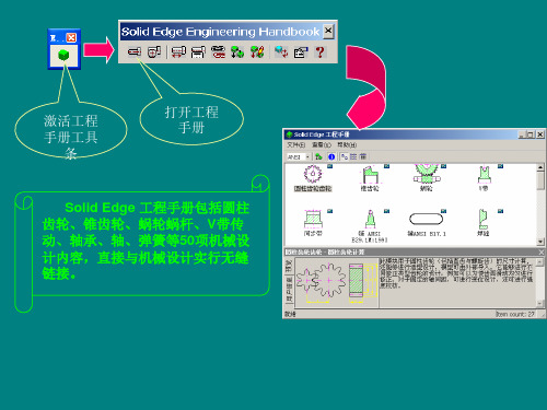
用户每次输入数据后,单击计算(Calculate)按钮进行计算以刷新 数据。单击数据库(Data base)按钮,则弹出正齿轮(Spur gearing)对话 框 , 单击设计(Design)则回到齿轮设计计算(Spur Gearing Calculation) 对话框, 单击创建(Generate)按钮,系统进入三维设计界面,生成齿轮 三维实体模型,另外也可点击Edit编辑进行数据修改。
在尺寸标注(Dimensions)选项卡上,可以选择设计主动齿轮或被动齿 轮。在公差(Tolerance)选项卡上可以选择齿轮设计精度等级和齿轮侧 隙。在载荷(Load)选项卡上,可以输入功率p (Power)、效率η (Efficiency)、转速n (Speed)和扭矩Mk (Torque),如图所示。
此时圆柱齿轮已经 按照所输入的数据 创建完成,再根据 齿轮的类型进行结 构设计。
2.运动仿真
仿真选项 智能仿真向导 插入联接 插入弹簧 模拟仿真 拖动零件 删除仿真结果 播放 ”弹出条、“重设置 干涉检查 输出AVI文件 输出VRML2文件 播放器
四杆机构的运动仿真
打开Solid Edge Tra首先给出“增加新零件吗?”对话框,单击否 。
仿真设置选项卡
仿真选项卡中,将延时置为1秒,总帧 数置为50,并选中模拟期间动画。单 击右侧的“模拟”按钮,系统即进行 动画演示。
SolidWorks机械设计基础操作及界面介绍

SolidWorks机械设计基础操作及界面介绍SolidWorks是一款功能强大的三维机械设计软件,广泛应用于各个领域的产品设计与开发。
本文将介绍SolidWorks的基础操作和界面布局,帮助读者快速上手使用这一软件。
一、软件安装与启动首先,需要下载并安装SolidWorks软件。
在确保自己的电脑系统符合要求后,双击安装程序,并按照提示进行安装。
安装完成后,点击桌面上的SolidWorks图标启动软件。
软件启动后,将会出现主界面,包括菜单栏、工具栏、特征树、图形区等组件,接下来我们将详细介绍这些组件的功能和使用。
二、软件界面布局1. 菜单栏:位于软件的顶部,包含了各种功能选项。
通过点击不同的菜单,可以进行模型的创建、编辑、保存等操作。
2. 工具栏:位于菜单栏的下方,包含了常用的工具快捷按钮,可直接点击进行相应操作,节省了时间和操作步骤。
3. 特征树:位于左侧面板,在创建模型时会自动生成特征树,显示了模型中各个特征的层次关系。
可以通过特征树对模型进行编辑和调整。
4. 图形区:位于右侧面板,用于显示模型的三维图形。
可以通过鼠标左键拖动、旋转和缩放模型,在设计过程中提供了清晰、直观的展示。
三、基础操作1. 创建模型:在菜单栏中选择“文件”→“新建”,弹出新建对话框。
选择好文件类型后,点击“确定”,即可创建一个新的模型。
2. 绘制几何图形:在绘图工具栏中,选择所需的图形工具,如直线、圆、矩形等。
在图形区中点击确定起点和终点或圆心和半径,即可绘制出相应的几何图形。
3. 编辑特征:通过特征树选择要编辑的特征,在菜单栏中选择“编辑”→“修改属性”,即可对选中的特征进行修改。
可以调整尺寸、形状等参数,实现设计的需要。
4. 组装与装配:在特征树中选择不同的零件,使用快捷键Ctrl+C和Ctrl+V实现复制和粘贴。
将零件逐一拖入图形区,通过拖放和对齐操作,完成组装和装配。
5. 渲染与动画:在菜单栏中选择“渲染”或“动画”,可以对模型进行渲染和动画效果的添加。
solidworks设计说明书
目录一、设计目的与意义 (2)二、主要尺寸的确定 (2)2.1涡轮蜗杆的选定 (2)2.2 轴承的选取及轴的设计 (3)2.3键的设计 (3)2.4箱体 (3)2.5 减速器附件说明 (4)2.6装配图设计 (6)2.7零件图设计 (9)三、心得体会 (11)四、建议 (12)五、参考文献 (12)一、设计目的与意义蜗杆在上的蜗杆减速器的设计,要求传动比为20。
使用solidworks 软件完成机盖、涡轮或涡轮轴、轴承、其他零件等的三维实体造型。
绘制机盖或机座、涡轮、轴的工程图,并标注规范。
通过本课程设计,巩固通过课程学到的知识,提高动手实践能力,达到使同学们在综合运用计算机进行机械设计尤其是进行较为复杂的装配图和零件图的绘制、一般的三维实体造型及进行三维装配、图形仿真方面的能力得到提高,进一步提高二维图形的绘制能力。
二、主要尺寸的确定2.1 涡轮蜗杆的选定已知i=20 i=n1/n2=z1/z2n1为蜗杆转速,n2为涡轮转速。
z1为蜗杆头数,z2为涡轮齿数。
查《机械设计》P244表11-1,取z1=2,z2=41。
查《机械设计》P245表11-2,取中心距a=100mm,模数m=4mm,蜗杆分度圆直径d1=40mm,直径系数q=10.00,导程角γ=11°18′36",变位系数x2=-0.500。
实际生成中心距a=102mm。
查《机械设计》P248表11-3,计算得涡轮齿宽为40mm,取蜗杆长度为80mm。
2.2轴承的选取及轴的设计选用圆锥滚子轴承。
查《机械设计课程设计》P182表17-6选用30207和30210圆锥滚子轴承。
30207 d=35mm ,D=72mm ,T=18.25mm ,d a =42mm30210 d=50mm ,D=90mm ,T=21.75mm ,d a =57mm轴结构的工艺性:取轴端倒角为 451⨯,按规定确定各轴肩圆角半径,键槽位于同一轴线上。
solidworks机械设计及制图规范参考(适合所有机械行业)
solidworks机械设计及制图规范参考(适合所有机械行业)1. 总则为规范机械制图的格式,使之简单化、标准化,以便于网络共享,特制订机械制图规范。
此规范适用机械工程制图中使用Solidworks及Creo软件绘制的三维图及工程图样,在使用过程中如涉及本规范未规定的内容,应符合有关国家标准及规定。
2. 制图软件使用规范此部分内容以Solidworks软件为例进行规定,Creo软件按照此标准进行相应配置及使用。
2.1. 模板选择使用solidworks建立零件模型及装配体模型时,必须使用公司指定的模型模板,模板名称为“零件—某某公司”,“装配体—某某公司”。
使用solidworks建立工程图时,必须使用指定的工程图模。
工程图模板选择好后,选择合适的图纸格式。
根据国家标准规定,制定了5种幅面的图纸格式,包括“A0”、“A1”、“A2”、“A3”、“A4纵”。
需特别说明的是,A4图纸在使用时不允许使用横向图幅。
2.2. 草图规范建立新零件后,若是拉伸特征,草图基准面选择上视基准面;若是旋转特征,草图基准面选择右视或前视基准面。
拉伸特征旋转特征绘制的草图必须完全定义(草图颜色全部变为黑色),应尽量使用约束(垂直、平行、相等、对称、相切等)而非尺寸标注来使草图完全定义。
2.3. 模型规范零件及装配体模型建立完成后,必须填写“自定义属性卡”,内容包括:名称,图样代号、物号、材料、备注。
零件及装配体模型名称命名规则为图号+名称,图号与名称与属性卡中填写的一致。
2.4. 图号规范编制方法为:产品代号+序号,如XXX-01-02-00、XXX-01-02-01。
其中,“XXX”表示产品代号,末位数为“00”表示为装配图,末位数为“01”、“02”……等编号时,表示为零件图。
“XXX”的命名规则为:机器简称的英文首字母+设备主参数,例如MXJ800表示磨削机,800代表加工最大直径为800mm。
一般地,一个产品的图号最多只能分为四层零件图,详细划分规则入下图:总装图XXX-00第一层零件图XXX-01第一层装配图XXX-02-00…………2.5. 格式规范1)字体总的要求图面清晰,字体大小适当,字体(汉字)采用汉仪长仿宋体。
Solidworks2016机械设计教程lidworks简介20
*** SolidWorks 工作界面
设计树
下拉菜单区
工具栏按钮区
任务窗格
图1.3.1 SolidWorks工作界面
图形区 状态栏
*** SolidWorks鼠标的操作
*** 鼠标的操作 SolidWorks中鼠标操作的说明如下: 缩放图形区:滚动鼠标中键滚轮,向前滚动 鼠标可看到图形在缩小,向后移动鼠标可看到图 形在变大。 平移图形区:先按住Ctrl键,然后按住鼠标中 键,移动鼠标,可看到图形跟着鼠标移动。 旋转图形区:按住鼠标中键,移动鼠标可看 到图形在旋转。
SolidWorks2016 机械设计 教程
詹迪维 主编
机械工业出版社
第1章 SolidWorks简介
本章内容主要包括: SolidWorks软件的主要功能模块简介。 创建用户文件夹。 SolidWorks工作界面。 SolidWorks鼠标的操作。 环境设置。 工作界面的自定义。
*** SolidWorks 功能概述
*** 对象的选择 1.选取单个对象 2.选取多个对象 3.利用“选择过滤器”工具条选取对象。
A2 A4
A6 A8 A10 A12 A14 A16 A18 A20 A22 A24 A26 A28
A1 A3
A5 A7 A9 A11 A13 A15 A17 A19 A21 A23 A25 A27
图1.4.1 “选择过滤器(I)”工具条
1.零件 (1)实体建模。 (2)曲面建模。 (3)模具设计。 (4)钣金设计。 (5)焊件设计。 2.装配
3.工程图
*** 创建用户文件夹
使用SolidWorks软件时,应该注意文件的目录管理。如果 文件管理混乱,会造成系统找不到正确的相关文件,从而严重 影响SolidWorks软件的全相关性,同时也会使文件的保存、删 除等操作产生混乱。
SOLIDWORKS 设计解决方案说明书
SOLIDWORKS SOLUTIONS ENGINEERING AND DESIGN TOOLSTO DRIVE YOUR BUSINESSPOWERFUL,YET SIMPLE SOLUTIONS TO HELP YOU GROW YOUR BUSINESS SOLIDWORKS® design solutions help designers, engineers, and manufacturers create and deliver great products. Our integrated, powerful yet easy-to-use solutions cover all aspects of your product developmen t process with a seamless workflow that simplifies the development process for even the most complex designs. SOLIDWORKS helps you eliminate barriers to innovation so your team can work more efficiently, reduce development time and cost, and get the information you need at exactly theright time for making better design decisions.DESIGNInspiring innovation from concept through manufacturingThe SOL IDWORKS solution suite begins with design, from capturing and collaborating on concepts, to detailing parts and assemblies, through to manufacturing. Used by more than two million designers and engineers around the world, SOLIDWORKS helps drive smarter, faster product development. SOL IDWORKS conceptual design solutions help you capture and collaborate on mechanical and industrial concepts; with SOL IDWORKS mechanical design you can develop even the most complex designs more quickly; SOL IDWORKS assembly modeling enables you to represent and interact with any size assemblies in real time; while SOLIDWORKS 3D CAD gives you tools to create stylized, ergonomic products.• Advance your ideas from concept to production using rich3D models• Part and assembly 3D modeling and 2D drawings• Design reuse and automation• Animations and photorealistic renderings• Verify that your design can be produced before you goto manufacturing• Design for manufacturability tools• Manufacturing cost estimation• Routed systems• Share CAD data with others and easily collaborate on product designs• Data exchange tools for both import and export of geometry to and from other systems• Secure, private design communities to capture concept ideas, requirements, and feedback from colleagues, suppliers, and customers SIMULATIONAdvanced simulation that’s powerful and easy to use for both engineers and specialistsSOL IDWORKS Simulation helps product engineers ask—and answer—important and complex engineering questions throughout the design process. You can test your designs to ensure that product behavior will avoid failures, be reliable, and achieve design requirements, with analysis for:• Structural – fi nite element analysis (FEA)• Fluid fl ow and heat transfer – computational fl uid dynamics (CFD)• Plastics injection molding (PIM)• Environmental impact• Time-based motionPowerful results visualization shows the structural forces affecting your design—displaying stresses, displacement, lifetime, and temperature. You can calculate measurements for any point, surface, or volume, and then graph and list results for all types of simulations.Intuitive CFD simulation takes advantage of CAD integration, advanced geometry meshing, solution convergence, and automatic fl ow regime determination without sacrifi cing ease of use or accuracy. Product mechanical Engineers and CFD experts alike can predict flow fields, mixing processes, and heat transfer, and directly determine pressure drop, comfort parameters, fl uid forces, and fl uid structure interaction during design.Now, every designer can answer the most complex “what if” questions, reduce the number of prototypes, ensure greater product accuracy, and get to market faster. Sophisticated and easy to use, SOL IDWORKS Simulation works seamlessly with SOLIDWORKS 3D CAD, so you can use it throughout the product design process.“ S OLIDWORKS has allowed us to reduce design cycle times signifi cantly, which saves time and money, while simultaneously improving quality.”— Mike Derus, Lead Engineer, THE OUTDOOR GROUP LLCmetryCommunicate with co-workers,manufacturing, customers and your entire supply chain knowing your data is safe,secure and at the right revision levelregardless of your location.DATA MANAGEMENTTake control of your data to enhance collaboration and innovationSOL IDWORKS Enterprise Product Data Management (EPDM) enables designers and engineers across your organization to quickly and effi ciently fi nd, share, and reuse data, helping improve quality and collaboration. Enterprise-wide version control and integrated workfl ows help automate your design processes. Easy to implement, SOLIDWORKS EPDM can scale from small and mid-sized installations to hundreds of designers and engineers in distributed offi ces around the world.• Rapidly find and use data – Ensure your team always has the right version, avoiding costly mistakes• Collaborate without boundaries – Give your teams and partners quick access, even across continents and time zones, while maintaining version control• Access with mobile connectivity – Browse folders, view fi le information and thumbnails, search, and change fi les from any device• Be productive fast – Experience a fast learning curve and ease of use with an intuitive Windows ® Explorer interface, personalized menus, and quick-access features that remove desktop clutter• Streamline processes – Simplify administrative steps like approvals and sign-offs, and minimize administrative work, while maintaining accuracy and accountabilityTECHNICAL COMMUNICATIONAdd a new dimension to all the technical communication deliverables you need to produceSOLIDWORKS Technical Communication applications help you improve the creation of customer technical documentation, sales materials and presentations, and documentation for inspection and manufacturing. You use your existing design data to produce your materials, helping you work faster and more effi ciently. For inspection tasks, SOL IDWORKS can automatically create inspection documents by leveraging existing 2D legacy data. Quality departments often require drawings with balloon callouts, reports for inspection, or additional deliverables for the inspection process. Designers, engineers, and quality inspectors are typically tasked with manually creating these documents. Now with SOL IDWORKS, this process is automated, improving productivity and accuracy.SOLIDWORKS can communicate PMI directly in 3D, including 3D model data in industry-standard fi le formats (such asSOLIDWORKS fi les, eDrawings ®, and 3D PDF). This information guides the manufacturing process, helping to streamline production, cut cycle time, reduce errors, and comply with industry standards. By removing time-consuming 2D processes, companies using model-based operation have reduced development costs by up to 50 percent, especially saving on rework, scrap, tooling, and fabrication.SOLIDWORKS software offers the tools to start creating product communication—such as high-quality graphics, illustrations, and interactive 3D animations—early in the design process, keep it updated, and deliver it on time. The easy-to-use software enables companies, including nontechnical users, to leverage existing 3D CAD data to create dynamic product images and animations to help clearly present even the mostcomplex data and designs.Enhance your electromechanicaldesign by integrating the electrical design into the 3D environment for complete and accurate Bill of Materials (BOM) including wires, cables, harnesses and electrical components.Create electromechanical projects quickly with powerful yet easy to use Electrical Schematic design tools.ELECTRICAL DESIGNSimplify electrical schematic creation and integrated electrical system designIn electromechanical design, creating design elements and defi ning the electrical interconnect of wires, cables, and harnesses is often a laborious and error-prone process. SOL IDWORKS offers a range of intuitive electrical schematic and 3D design functionality to meet the needs of electrical engineers and help simplify your electrical schematic creation. Bidirectional integration in real time between electrical and mechanical designs helps improve collaboration and productivity for fewer product delays, more consistent and standardized designs, lower costs, and faster time-to-market. Powerful, easy-to-use schematic design tools help drive rapid development, with built-in libraries of symbols, manufacturer part information, and 3D component models providing common, reusable materials that help optimize design reuse.You can use advanced SOL IDWORKS routing technology to automatically interconnect electrical design elements within the 3D model. Then, determine optimal lengths for wires, cables, and harnesses, all while maintaining design and BOM synchronization between electrical and mechanical designs.“ S OLIDWORKS Electrical makes us more accurate and effi cient in all facets of development—from design to collaboration to production.”— Ryan Helminen, Project Engineer, GLSV, Inc.Create el quicklyElectric Enhance your electromec design by integrating th electrical design into theenvironment for complaccurate Bill of Materiaincluding wires, cableand electrical componlectrical Schematic design tools.eate electromechanical projects uickly with powerful yet easy to use ectrical Schematic design tools.ENGINEERING AND DESIGN SOLUTIONS FOR ALL ASPECTS OF YOUR DEVELOPMENT PROCESSSOL IDWORKS covers all aspects of your product development process from start to fi nish, with integrated design, simulation, technical communication, and data management. Product Engineers can perform multiple development tasks with ease, shortening their design cycle, increasing productivity, and delivering innovative products to market faster.The SOLIDWORKS suite of solutions covers:• 3D mechanical design• Embedded electrical schematic design and electromechanical design• Simulation for analysis of structural, CFD, plastic injection molding, environmental, and motion parameters• Data management for secure, effi cient storage and search • Technical communication applications and tools for creating dynamic graphical content, inspection documentation, and model-based 3D product and manufacturing information (PMI)MECHANICAL DESIGNELECTRICAL DESIGN PRELIMINARYPROJECT AND CONCEPTSTYPICAL SERIAL PROCESS SOLIDWORKS PROPOSALOPERATIONSOPERATIONSPRELIMINARY PROJECT AND CONCEPTSTECHNICALCOMMUNICATIONDESIGNVALIDATION TECHNICAL COMMUNICATIONPROJECT DATE MANAGEMENTDESIGN VALIDATION INTEGRATED ELECTRICAL AND MECHANCIAL DESIGNSOLIDWORKS ADVANTAGESOLIDWORKS products are easy to learn, easy to use, and work together to help you design products better, faster, and more cost-effectively. SOL IDWORKS Solutions help you maximize productivity and develop products through an integrated, concurrent workfl ow process to help simplify even the most complex project development, shorten your design time, and get to market faster.SOLIDWORKS COMMUNITYThe SOL IDWORKS Community is active, large, and growing, comprising more than two million users, over 180,000 organizations, more than 300 solution partners, and hundreds of value-added resellers worldwide. This community has an important voice in shaping SOLIDWORKS solutions, with their feedback driving our product enhancements and innovations, year after year.Available tools like SOL IDWORKS eDrawings and DraftSight ®simplify and expand your ability to share and collaborate on designs with colleagues and clients. MySolidWorks is your place for all things SOLIDWORKS to help support your success. You can log in to for a central technical reference resource, including access to 100+ hours of training materials, certifi cation prep courses and tests, VAR technical content, and online file exchange.Our 3D EXPERIENCE platform powers our brand applications, serving 12 industries, and provides a rich portfolio of industry solution experiences.Dassault Systèmes, the 3D EXPERIENCE ® Company, provides business and people with virtual universes to imagine sustainable innovations. Its world-leading solutions transform the way products are designed, produced, and supported. Dassault Systèmes’ collaborative solutions foster social innovation, expanding possibilities for the virtual world to improve the real world. The group brings value to over 170,000 customers of all sizes in all industries in more than 140 countries. For more information, visit .©2014 D a s s a u l t S y s t èm e s . A l l r i g h t s r e s e r v e d . 3D E X P E R I E N C E , t h e C o m p a s s i c o n a n d t h e 3D S l o g o , C A T I A , S O L I D W O R K S , E N O V I A , D E L M I A , S I M U L I A , G E O V I A , E X A L E A D , 3D V I A , B I O V I A , a n d N E T V I B E S a r e c o m m e r c i a l t r a d e m a r k s o r r e g i s t e r e d t r a d e m a r k s o f D a s s a u l t S y s t èm e s o r i t s s u b s i d i a r i e s i n t h e U .S . a n d /o r o t h e r c o u n t r i e s . A l l o t h e r t r a d e m a r k s a r e o w n e d b y t h e i r r e s p e c t i v e o w n e r s . U s e o f a n y D a s s a u l t S y s t èm e s o r i t s s u b s i d i a r i e s t r a d e m a r k s i s s u b j e c t t o t h e i r e x p r e s s w r i t t e n a p p r o v a l . M K S O L U D S E N G 0714Corporate Headquarters Dassault Systèmes10, rue Marcel Dassault CS 4050178946 Vélizy-Villacoublay Cedex FranceAmericasDassault Systèmes SolidWorks Corporation 175 Wyman StreetWaltham, MA 02451 USA Phone:180****9000Outside the US: +1 781 810 5011Email:**************************Asia-Pacifi cDassault Systèmes K.K.ThnkPark Tower2-1-1 Osaki, Shinagawa-ku,Tokyo 141-6020Japan。
- 1、下载文档前请自行甄别文档内容的完整性,平台不提供额外的编辑、内容补充、找答案等附加服务。
- 2、"仅部分预览"的文档,不可在线预览部分如存在完整性等问题,可反馈申请退款(可完整预览的文档不适用该条件!)。
- 3、如文档侵犯您的权益,请联系客服反馈,我们会尽快为您处理(人工客服工作时间:9:00-18:30)。
井冈山大学
Soildworks机械设计
机电工程学院
班级:11机制本二班
学号:110612029
姓名:罗斌
指导老师:康志成
目录
一、设计内容 (2)
二、齿轮传动总体设计 (4)
三、各齿轮的设计 (4)
1、结构尺寸设计 (4)
2、材料的选择,结构形式设计 (4)
3、3D软件设计零件 (6)
四、轴的设计 (7)
五、机架的设计 (8)
六、零件的装配 (9)
七、设计小结 (10)
八、参考资料 (10)
一、设计内容 1. 已知条件:
电机功率4kw ,小带轮转速n 1=960r/min, 传动比i=3.5,传动比允许误差≤±5%;轻度冲击;两班工作制。
2. 设计内容和要求。
1) V 带传动的设计计算。
2) 轴径设计。
取45号钢时,按下式估算: dmin=11003.1/3⨯≥n p ,并圆整; 3) V 带轮的结构设计。
选择带轮的材料、结构形式、计算基本结构尺寸; 4) 用3D 软件设计零件及装配图,并标注主要的特征尺寸; 5) 生成大带轮零件图(工程图),并标注尺寸、粗糙度等。
二、 V 带传动总体设计 1)确定计算功率。
由表13-8得工作情况系数K α=1.2,故
Pc=K α=1.2×4=4.8kw
2)选择V 带的带型。
根据带轮的功率Pc=4.8、小带轮的转速n 1=960r/min ,由图13-15查得此坐标位于A 型与B 型交界处,本次试验选用B 型。
3)求大、小带轮轮基准直径d ₂、d ₁
由表13-9,d ₁应不小于125,现取d ₁=140mm ,由式(13-9)得 d ₂=(n ₁/n ₂) ×d ₁ (1-ε)=3.5×140×(1-0.02)=480.2
由表13-9取d2=500。
4)验算带速ν
ν=πd₁n₁/(60×1000)=π×140×960/(60×1000)m/s=7.0m/s 带速在5~25m/s范围内,合适。
5)确定V带基准长度L和中心距a。
初步选取中心距a。
=1.5(d1+d2)=1.5×(140+500)mm=960mm
由式L。
=2a。
+(π/2)×(d₁+d₂)+(d₂-d₁)²/(4a。
)=2959mm
查表13-2,对B型带选用Ld=3150mm。
再由式(13-16)计算实际中心距a≈a。
+(Ld-L。
)/2=1055.5mm
6)验算小带轮包角α₁
由式(13-1)得
α₁=180°-57.3°×(d₂-d₁)/a=160.5°>120°,合适。
7)求V带根数z
由式(13-15)得
z=Pc/[(P。
+ΔP。
)KaKl
今n₁=960r/min,d₁=140mm,查表13-3得
P。
=2.08kw,又已知i=3.5
查表13-5得ΔP=0.30kw
由α₁=160.5°查表13-7得Kα=0.97,查表13-2得Kl=1.07,由此可得z=4.8/[(2.08+0.30)×0.95×1.07=1.984
取2根。
8)求作用在带轮上的压力FQ
查表13-1得q=0.17kg/m ,故由式(13-17)得单根V 带的初拉力 F 。
=500Pc(2.5/K α-1)/zv +qv ²=288N 作用在轴上的压力
FQ=2zF 。
Sin (α₁/2)=1135.3N 三、 各带轮的设计。
1.结构尺寸设计。
由B 型带,查表13-10可得
︒
=====+-====±=====34δ148mm 4×2140++2ha dd da 432)1(125.1119mm е)3.019(1445.30.14min
min min mm
f e z B mm
f mm f
mm e mm
h mm h mm h mm b f a a d ;取,去;;
轴径:
d(min)1 03.1/1103⨯⨯≥n p =18.23mm , d(min)2 03.1/1103⨯⨯≥n p =27.68mm ,
取mm d d 251=,mm d d 352=。
2.材料的选择,结构形式设计。
齿轮材料选择塑料金属齿轮,适用于存在污染及多粉尘的不利环境,中负荷和中低转速,齿轮材料选择塑料金属齿轮,而且成本低。
3. 3D 软件设计零件。
图1 小齿轮
图2 齿轮轴
图2 大带轮草图和大带轮实体
四、轴的设计。
根据带轮的轴径和厚度,设计出轴的尺寸。
绘制出轴的草图和3D图
如下:
图3 轮轴草图和轮轴实体
五、 机架的设计。
根据轴的尺寸和带轮的尺寸,设计机架的尺寸。
绘出机架的
草图和3D图,如下:
图4 架草图和机架实体
六、零件的装配。
根据总体设计中的中心距尺寸,在SolidWorks中将各零件装
配起来,并绘出V型带的零件图。
图5 V型带
图6 装配体
七、小结。
在做实验前要准备充分,特别是先要计算好各种数据,否则
去了也白去。
在做实验的过程中常常会遇到好些问题,这主要是由于对Soildworks不熟悉的结果,只要多去练习几次就可以解决。
还有,遇到不懂得地方需要尽快去问老师或则同学,不然就算想好久也不会有什么结果的。
通过此次试验,已经对Soildworks有所了解了。
八、参考资料。
【1】《机械设计基础》杨可桢、程光蕴、李仲生主编高等教育出版社【2】《机械设计课程设计》许瑛主编北京大学出版社【3】《机械原理》(第七版)孙桓、陈作模、葛文杰主编高等教育出版社【4】《机械零件CAD设计上机实验指导书》朱保利编自编教材【5】《画法几何与机械制图》冯开平、左宗义主编华南理工大学出版社。