Solidworks机械设计
Solidworks的机械机构和连杆设计技巧与实践
Solidworks的机械机构和连杆设计技巧与实践Solidworks是一款常用于机械设计的CAD软件,其强大的建模和分析功能使得机械工程师能够更加高效地设计和优化机械机构和连杆。
本文将介绍一些Solidworks中的机械机构和连杆设计技巧,并通过实践案例进一步说明其应用。
在Solidworks中,机械机构的设计可以使用装配体功能来实现。
装配体是由多个零件组合而成的集合体,可以用于模拟机械系统的运动和功能。
在设计机械机构时,首先需要明确系统的运动要求,并合理选择机械连接的方式。
常见的机械连接方式包括配合连接、螺纹连接和焊接连接等。
对于配合连接,Solidworks提供了丰富的配合关系选项,例如圆栓配合、轴向配合和轴向销等。
根据实际情况选择合适的配合关系,并根据制造工艺要求进行尺寸设计。
在设计过程中,可以使用Solidworks的装配体模拟功能来检查配合关系的正确性和运动约束。
同时,可以通过设置装配体关系的限制条件和运动学参数,模拟机械系统的运动过程,并进行性能评估和优化。
螺纹连接是机械设计中常用的连接方式之一。
在Solidworks中,可以使用螺纹特征功能来创建螺纹零件。
通过选择合适的螺纹类型、螺纹尺寸和螺纹位置等参数,可以快速而精确地生成螺纹零件。
同时,Solidworks还提供了螺纹的装配体关系选项,可以将螺纹零件与其他零件相连接,并确保其螺纹的正确配合。
在机械设计中,连杆是常用于传递运动和力的重要组件。
Solidworks中有多种方式可以实现连杆的设计。
一种常见的方法是使用装配体功能并设置连杆的运动约束。
例如,可以将连杆的两个关键点与相邻零件的表面关联,从而确定连杆的位置和运动约束。
此外,Solidworks还提供了创建齿轮、链条和曲柄等特殊连杆的工具和功能,可以根据实际需要进行设计。
为了更好地理解Solidworks中的机械机构和连杆设计技巧,下面将通过一个实践案例进行说明。
假设我们需要设计一个双曲柄连杆机构,用于将旋转运动转换为直线运动。
SolidWorks 分析指南:机械设计师的关键性能问题解决方案说明书
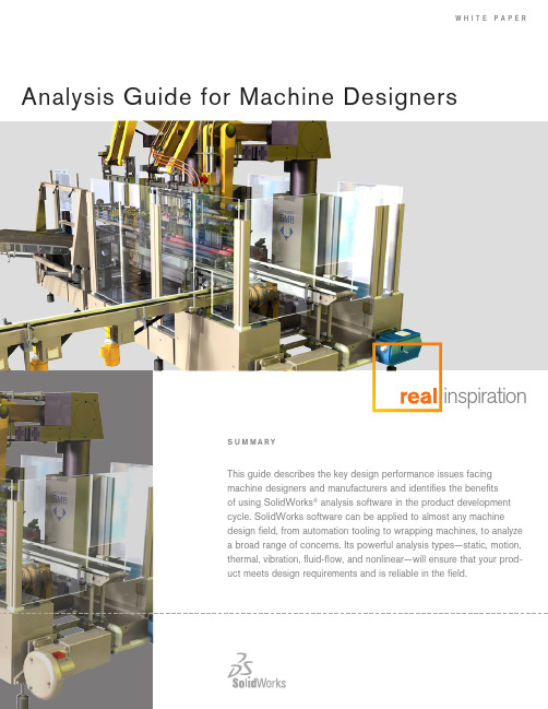
w h i t e p A p e R Analysis Guide for Machine DesignersintroductionAnalysis and simulation software is an indispensable tool in the developmentof large-scale machinery. These tools allow the developer to evaluate designsearly in the design cycle, determine causes of premature failures in the field,quickly explore design changes aimed at reducing cost and weight, and deter-mine the product’s factor of safety. Use of analysis tools is of particular valueto machine designers due to the size and complexity of the systems they aredeveloping. Analysis tools can identify design issues that may elude a design-er’s review simply because of the dynamic nature of machinery’s many movingparts.Analysis tools can identify designissues that may elude a designer’sreview simply because of the dy-namic nature of machinery’s manymoving parts.FIGure 1:INNer ArM OF rOBOT DeSIGNeD BY FANuC rOBOTICSThe unyielding demands upon machinery manufacturers by customers andthe market to create systems that are cheaper, more reliable, and more pro-ductive necessitate that companies that wish to remain successful utilize allthe tools available to them. These analysis tools reduce product developmentcosts through a reduction of late engineering changes. They ensure productsreach the market promptly, allowing the product to capture the largest pieceof the market possible. Finally, it allows engineers to experiment with materialsand designs that can result in products of minimal weight and cost. Analysissoftware enables engineers to simulate design performance and identify andaddress potential design problems before prototyping and production.Analysis at the forefront of machine design product developmentRegardless of the specific application, machine designers are under pressurefrom their customers: increase reliability and longevity; be quicker to marketwith new, improved products; reduce product weight and cost; and increaseproductivity. Working in this type of environment, engineers have little time toproduce multiple prototypes and use trial and error to gain a better understand-ing of the physical behavior of their designs. Yet, that information is vital forproducing innovative, high-quality products.FIGure 2:FANuC rOBOTICS TAKeS FuLL ADVANTAGe OF THe SOLID MODeLer INSOLIDWOrKS SIMuLATION.Analysis tools help machine designers understand the physical behavior of their designs quickly without resorting to expensive prototypes and physical tests that extend the product design cycle. Analysis tools can substantially reduce the number of ecos, missed deadlines due to redesigns late in thedesign cycle, and costly redesigns at manufacturing time. All of these markedly decrease development costs and time-to-market. Further, these tools increase communication between design, sales, marketing, manufacturing, and the cus-tomer through their easy-to-read and -understand graphical results.Application areas• Production equipment: hallmark cards, food production• industrial Robots and Robotic systems: design optimization, failure analysis • industrial Food Machinery• Packaging equipment• electromechanical systems: heating• Printed circuit Boards: semiconductors, heat sinks, MeMs• cooling systems: fans, motors, air flows• electronic systems: antennas, transmitters, switches• Automation Tooling• Aerating Machines, for beverages• Bag opening, Filling, and closing Machines• Bottling Machinery: washing, sterilizing, filling, capping, and labeling• Bread-wrapping Machines• carton-packing Machines• label Moisteners, industrial type• labeling Machinery, industrial type• Wrapping MachinesAnalysis tools help machine design-ers understand the physical behaviorof their designs quickly withoutresorting to expensive prototypesand physical tests that extend the product design cycle.Scope of analysis• design verification/validation: Will this design work? Will this design behave the way i think it will?• Relative merit: Which of these candidate designs is the best? how can i weed out and eliminate poor-functioning designs?• Proof of concept: Testing radical new concepts without producing prototypes • durability and reliability: Fatigue/failure analysis, drop tests, shake simulationstight integration with 3D CAD The solidWorks 3d cAd system, the standard for 3d design, is tightly inte-grated with all major cAd software. This means that engineers can use solidWorks analysis software directly on the cAd model and do not needto remodel designs to take advantage of analysis technology.FIGure 3:HALLMArK CArDS DeSIGNS CArD-MANuFACTurING MACHINerY uSING SOLIDWOrKS SIMuLATION.“what if” studiesA clear advantage of performing “virtual” testing using computer simulations over physical testing, beyond the cost and time savings, is the ability to quickly compare many designs incorporating different materials, part geometries, assembly configurations, subsystems, and more. Using analysis to conduct “what if” studies—what if i tried this material, or what if i used this type of mechanism—can help engineers identify the best material and mechanical design for a particular function. Using computational model and analysis soft-ware to perform “what if” evaluations saves time and money and can help to improve design performance. By coupling analysis studies with solidWorks configuration Management, the designer can quickly converge on the best-form design solution over many degrees of freedom.Using computational model andanalysis software to perform “whatif” evaluations saves time and moneyand can help to improve design performance.companies that use analysis to address these issues at the design state develop a clear advantage over their competitors.FIGure 4:MODuLAr AND CuSTOM AIr HANDLerS Are IDeAL prODuCTS FOr ANALYSIS BeCAuSe THeY MuST Be ABLe TO HeAT, COOL, HuMIDIFY, AND DeHuMIDIFY AIr AS WeLL AS FILTer pArTICLeS.powerful analysis types—static, motion, thermal, vibration,fluid-flow, nonlinearMachine designers must work with systems of amazing complexity and vari-ability. The kinematics and dynamics of all of the system’s moving partsand their potential for interference requires a great amount of design effort. Thermal effects of the heat-producing components upon the rest of the systems can be difficult to predict and design around. Vibration and other structural issues can lead to part failures, poor performance, and other opera-tional issues. companies that use analysis to address these issues at the design state develop a clear advantage over their competitors. solidWorks analysis software helps to ensure that these considerations are addressed early in the product development cycle, enabling manufacturers to accelerate time-to-market and reduce development costs while producing higher-quality products with fewer warranty issues. Using a range of analysis technologies, solidWorks software helps engineers to ensure that a product’s behavior will be within design limits, reliable, and free of the risk of thermal, electromag-netic, or stress-induced failures.FIGure 5:CALCuLATING THe CrITICAL FOrCeS OF A rOLLer ON A SHeeTer HeAD TAKeSJuST MINuTeS FOr CASA HerrerA.• static analysis is a tool that empowers the machine designer to avoid cata-strophic immediate or long-term failure modes and determine if redesign of one or more of the core elements is necessary. designers can study the stresses or deflections in the device and compare it against allowable lev-els to predict failure. solidWorks simulation has the ability to analyze shells using solidWorks surfaces and by extracting mid surfaces of thin-walled structures, particularly useful in machines that incorporate sheet metal i n their designs. Through static analysis, designers can optimize geometries, minimize weight and material usage, and determine the factor of safety built into each of their machines.• Motion analysis is also extremely valuable in the development of machinery in that they are by their nature extremely complex, dynamic assemblies. Running motion analysis allows designers to perform “virtual testing” before manufac-turing physical prototypes, saving time and money during the iterative designcycle. changes prior to “cutting metal” are far cheaper and quicker to enact. Motion analysis allows the designer to learn more about the machinery in the concept phase and perform dynamic interference detection prior to building engineering models.• Thermal analysis is critically important in machine design. Managing tempera-ture, whether it’s of printed circuit boards, mechanical devices, or of fluidic systems can be an important design challenge that an engineer must over-come. solidWorks simulation analysis software can perform steady-state or transient thermal analysis on parts or assemblies. After meshing the design, the designer sets any relevant constraints, then sets power or heat flux condi-tions associated with a geometrical feature of the model. Because compo-nent material properties include thermal conductivity, coefficient of thermal expansion, and heat capacity, the designer gets a realistic prediction of tem-perature distributions under prescribed loads and operating conditions.FIGure 6:eND-OF-ArM AuTOMATION TOOLING DeSIGNeD BY puSHCOrp, INC.• Vibration analysis is valuable in many types of machinery products. Many have motors, pumps, and other vibration sources that can adversely affect performance of surrounding electronic and mechanical devices. optimal per-formance, with a minimal amount of adverse effects on these components, requires an understanding of the natural frequencies at which a component or assembly will vibrate and the impact of any stresses or deflections thatUsing solidWorks simulationanalysis software, an engineer cansimulate the natural frequencies of a part or assembly.may occur. Using solidWorks simulation analysis software, an engineer can simulate the natural frequencies of a part or assembly and use this informa-tion to modify the design or materials used to avoid resonance and deflection in certain areas or improve performance. Random vibration analysis can also help engineers stiffen electrical systems that are designed to survive earth-quakes and represent a more cost-effective approach than conducting physi-cal shake tests. Analysis can be used to minimize frequency and vibration to minimize the perturbations’ effects on the system performance.FIGure 7:NeuMAG IMprOVeS NOZZLe DeSIGN WITH SOLIDWOrKS FLOW SIMuLATION.• Fluid-flow analysis has a number of applications in the machine designdomain. Fluid-flow properties play a large role in heat transfer analysis. large machinery generally has large heat sources such as power supplies and motors that require active cooling. convective and conjugative heat transfer are dependent on fluid-flow properties. Fluidic systems such as hydraulics can also be modeled and their designs evaluated. Third, this analysis can be used in the design process of fluidic components such as nozzles, valvings, pump systems, and lubrication systems. Whatever a manufacturer’s analytical needs, solidWorks Flow simulation offers high-powered computational flow dynamics (cFd) analysis for understanding the impact of fluid flow on tem-perature in electrical systems.• nonlinear analysis gives electronics and electrical product designers the ability to evaluate product performance within a complex, 3d-simulated environment, giving them a far more accurate determination of the different factors that may cause a device to fail. nonlinear analysis tools are effective for analyzing static and dynamic problems with geometric and material nonlinearity, hyper-elasticity, creep, thermo-plasticity, and viscoelasticity. solidWorks simulation Premium nonlinear analysis software can also analyze nonlinear contact prob-lems involving surface interactions of models with or without friction.FIGure 8:CYCLONIC INerTIAL SepArATOr BY DAVID rACHeLS AND HIS eNGINeerING TeAMlarge machinery generally has largeheat sources such as power supplies and motors that require active cooling.Assembly analysislarge-scale assembly analysis is absolutely critical for machinery designers. industrial machinery by its nature contains many complex subassemblies of many parts. As such, analysis on machine designs requires a wide range ofattachment, interconnection, and encapsulation methods. designers require that analysis run on their parts, subassemblies, and full assemblies. These assem-blies can be affected by heat, pressure, vibration, impacts, and electromagnetic fields at all levels of the design.FIGure 9:CHuCK DeSIGNeD BY SpeeDGrIp CHuCK INC.solidWorks simulation analysis software enables engineers to simulate all of these behaviors by allowing for the analysis of small or large cAd assemblies. The software allows engineers to assign different materials to different parts of the assembly and specify how the components will interact with each other. solidWorks simulation assembly gap/contact analysis allows you to simulate various real-life conditions for large machines.Many of what in the past have been physical tests on large machines can now be moved to computer simulations. drop tests, to ensure that shipping does not damage the machinery, can be performed during the design phase and easier, less costly changes can be made prior to physical prototyping and manufactur-ing. Thermal analysis can ensure that no components within the system become overheated and can aid in designing appropriate heating and cooling systems within the machinery. sources of vibration within a system can be modeled and their effects on surrounding components studied. This allows for effective isola-tion systems to be developed early in the design cycle.3D VisualizationsolidWorks simulation analysis tools enable analysis of machinery and large-scale industrial products at the component, assembly, and system levels.• 3d visualization provides a designer with a first check of design intent, proper operation, and aesthetics as the project develops.• 3d cAd enables the designer to view a product design from all angles and examine the internal parts of the product throughout the design process. This gives designers a clear and accurate review of parts and assemblies early in the design cycle.solidWorks simulation assemblygap/contact analysis allows you tosimulate various real-life conditions for large machines.• 3d visualization reduces communication and fabrication errors, saving development time by more effectively conveying design information so that designers can find problems early in the design cycle.• designers can view the product from all sides and look inside by hiding the outer enclosure or other parts.• 3d animations of simulations allow you to see how the machinery functions in the real world.• section plots allow you to see simulation results inside the part and not just on the surface.FiGURe 10:The Johnson coRPoRATion desiGns sYsTeMs FoR PRocess indUsTRies.Design communication and collaboration tools• design collaboration has become an increasingly important part of the product development process, enabling designers to share designs easily with anyone, anywhere.• collaboration tools offer new ways for product designers to work more effectively with other members of the development team. The ability to share design resources over the internet benefits all product designers, from inde-pendent consultants to engineers in large multinational corporations.• solidWorks simulation analysis tools allow designers to share analysis results in various formats such as:- hTMl reports of analysis results- VRMl files- AVi files- solidWorks simulation allows users to publish solidWorks edrawings ®files for analysis results.collaboration tools offer new waysfor product designers to work moreeffectively with other members of the development team.ConclusionMachinery manufacturers face relentless demands by customers and the market to create systems that are cheaper, more reliable, and more produc-tive. companies that wish to remain successful utilize all the tools available to them. With analysis and simulation tools, the developer can evaluate designs early in the design cycle, determine causes of premature failures in the field, quickly explore designs changes aimed at reducing cost and weight, and deter-mine the product’s factor of safety. Analysis tools are particularly valuable to machine designers due to the size and complexity of the systems they are developing. solidWorks simulation and analysis tools reduce product develop-ment costs, ensure products reach the market promptly, and allow engineers to experiment with materials and designs that can result in products of minimal weight and cost.。
Solidworks的机械设计和材料选择指南
Solidworks的机械设计和材料选择指南概述:Solidworks是一款广泛应用于机械设计领域的三维CAD软件,它提供了丰富的工具和功能,帮助工程师和设计师实现高质量的机械设计。
在这篇文章中,我们将探讨如何使用Solidworks进行机械设计,并介绍在设计过程中如何选择合适的材料。
机械设计指南:1. 确定设计目标和需求:在开始机械设计之前,明确设计的目标和需求非常重要。
这可以帮助确定设计的功能、性能和成本等方面。
了解产品的使用环境和应用要求,将有助于选择合适的材料和设计参数。
2. 了解Solidworks软件:在使用Solidworks进行机械设计之前,建议您熟悉软件的基本功能和操作。
学习如何创建零件、装配和绘制工程图等技能,可以提高设计的效率和质量。
3. 设计零件:使用Solidworks可以创建各种零件,如螺杆、轴、齿轮等。
在设计零件时,应注意以下几点:- 几何形状:根据设计需求使用适当的几何形状,例如圆柱体、立方体等。
- 尺寸和公差:确保零件的尺寸和公差满足设计要求,并且能够与其他零件正确配合。
- 特征和几何关系:利用Solidworks的特征和几何关系工具创建零件的功能和约束。
4. 部件装配:在Solidworks中,可以将各个零件装配在一起,创建完整的产品模型。
在进行部件装配时,请注意以下几点:- 组件位置和相对位置:确保零件装配后的位置和相对位置正确,并且能够满足设计要求。
- 零件配合和运动:确保各个零件之间的配合和运动满足设计要求,使用Solidworks的装配工具进行验证。
5. 工程图绘制:使用Solidworks可以快速绘制工程图,以便制造和装配产品。
在绘制工程图时,要注意以下几点:- 标题块和视图:确保工程图的标题块和视图符合标准,并能提供清晰的信息。
- 尺寸和标注:将零件的尺寸和标注添加到工程图中,以便制造和检验人员能够理解和操作。
- 图纸规范:遵循相关的图纸规范,确保工程图的准确性和可读性。
SOLIDWORKS2024机械设计实例教程教程

SOLIDWORKS2024机械设计实例教程教程本教程包含各种机械设计实例,涵盖了不同的设计领域和应用场景。
下面介绍五个实例:1.桥梁设计:本实例详细介绍了如何使用SOLIDWORKS进行桥梁设计。
从桥梁的草图到实际建模,再到材料选择和分析,读者将学习如何利用SOLIDWORKS进行桥梁设计的全部过程。
2.机械手臂设计:本实例引导读者通过使用SOLIDWORKS进行机械手臂建模和运动分析。
读者将学习如何使用SOLIDWORKS的装配功能组装机械手臂,并使用运动分析工具模拟机械手臂的运动。
3.汽车底盘设计:本实例介绍了如何使用SOLIDWORKS进行汽车底盘设计。
读者将学习如何制作汽车底盘的草图和建模,并使用SOLIDWORKS的模拟功能进行底盘的力学分析。
4.简单机械系统设计:本实例介绍了如何使用SOLIDWORKS设计简单的机械系统,比如螺旋传动和齿轮传动。
读者将学习如何通过使用SOLIDWORKS的装配和运动分析功能进行机械系统的建模和仿真。
5.管道系统设计:此实例详细介绍了如何使用SOLIDWORKS设计复杂的管道系统。
读者将学习如何使用SOLIDWORKS的管道和测量工具进行管道系统的建模和分析。
本教程不仅提供案例的详细步骤和示意图,还提供了一系列实用技巧和注意事项,以帮助读者更好地理解和掌握SOLIDWORKS的使用方法。
此外,也提供了相关的习题和练习,方便读者巩固所学知识。
总结,SOLIDWORKS2024机械设计实例教程是一本全面介绍SOLIDWORKS软件的机械设计实例的教程。
通过实际的案例和详细的步骤,读者可以快速掌握SOLIDWORKS的使用技巧,并将其应用于各种机械设计项目中。
这本教程对于机械设计师和工程师来说是一本非常有用的资料。
solidworks案例教程

solidworks案例教程SolidWorks案例教程导言SolidWorks是一款广泛应用于机械设计和工程领域的三维CAD软件。
它提供了一整套强大的工具和功能,帮助用户设计、模拟、分析和制造各种产品。
在本篇教程中,我们将介绍一些实际案例,以帮助您熟悉和掌握SolidWorks的使用。
案例一:零件设计在这个案例中,我们将设计一个简单的机械零件。
假设我们需要设计一个机械零件,具体要求如下:1. 长方体形状,尺寸为100mmx50mmx30mm;2. 顶部有一个直径为10mm的孔;3. 零件材质为铝合金。
首先,打开SolidWorks软件并创建一个新的零件文件。
然后,按照下面的步骤进行设计:1. 使用“长方体”工具创建一个100mmx50mmx30mm的长方体;2. 使用“圆柱体”工具在顶部创建一个直径为10mm的孔;3. 使用“填充”工具将零件表面设置为铝合金材质。
完成上述步骤后,保存并导出零件文件。
您现在已经成功设计了一个简单的机械零件。
在SolidWorks中可以进一步对零件进行分析、模拟和制造等操作。
案例二:装配设计在这个案例中,我们将学习如何使用SolidWorks进行装配设计。
假设我们需要设计一个简单的机械装配,具体要求如下:1. 包含两个零件:一个底座和一个支架;2. 底座和支架之间通过两个螺栓连接;3. 完成装配后,需要进行装配分析。
以下是设计步骤:1. 创建一个新的装配文件,并将底座和支架导入到装配文件中;2. 使用“配合关系”工具将底座和支架对齐,并使用“约束关系”工具将它们连接;3. 使用“螺栓”工具在底座和支架之间创建两个螺栓连接;4. 完成装配后,进行装配分析,检查装配的可行性和稳定性。
通过上述步骤,您已经成功地完成了一个简单的机械装配设计。
这个案例不仅帮助您熟悉SolidWorks中的装配设计工具,还让您了解了如何使用装配分析工具来优化设计。
案例三:静态分析在这个案例中,我们将学习如何使用SolidWorks进行静态分析。
SolidWorks是个三维机械设计软件
SolidWorks是个三维机械设计软件。
Solid Works本身含义是固体制作的意思。
SolidWorks 2008 的基本理念是帮助工程师设计伟大的产品。
配合3DLib插件,直接调用几十万模型库,更方便快捷完成设计。
具体体现在以下方面:
1. 提升客户体验:
改进三维显示效果。
SolidWorks 2008 提供了一种快速预览三维轻量化模型的技术,使得大装配模型的显示速度进一步提高。
同时,支持在设计界面下的真三维显示效果,达到了以往专门的三维渲染软件的显示效果。
方便地编辑大装配件。
可以便捷地从大装配件中选取一部分零部件进行显示、编辑,进行运动仿真。
强化了SWIFT技术。
在 SolidWorks 2007 已经推出的Sketch Expert、Mate Expert和Feature Expert的基础上,又推出了Corner Expert(在复杂的拓扑结构中自动生成合理的圆角)、Tolerance Expert(合理分配公差)和Large Assembly Expert(检查大装配是否正确),帮助客户更加简便地生产零件和装配结构。
最大限度地减少客户的重复操作,使用户在使用过程中,更加专注于设计本身。
2. 帮助客户设计更好的产品:
SolidWorks以往的版本中已经加入了CosmosXpress,让工程师在设计过程中可以体验仿真分析的效果。
而SolidWorks2008中将提供Cosmos MotionXpress(运动仿真分析)、Cosmos FloXpress和DFMXpress(可制造性的分析)等模块,使得工程师能够更好地进行设计验证。
solidworks机械设计
solidworks机械设计SolidWorks是一种专业的机械设计软件,广泛应用于各行各业的机械设计领域。
它提供了强大的功能和工具,可以帮助工程师们设计、模拟和制造各种机械产品。
首先,SolidWorks具有友好的用户界面和操作方式。
它使用直观的命令和工具栏,使用户能够轻松掌握软件的操作,从而提高工程师的工作效率。
其次,SolidWorks提供了全面的二维和三维设计功能。
工程师可以使用2D草图工具创建包括直线、圆弧、矩形等几何图形,并将其转换为3D实体,然后根据需要进行进一步的设计和修改。
此外,SolidWorks还提供了先进的3D建模功能,可以实现复杂的曲面和实体建模,满足各种复杂设计的需求。
SolidWorks还具有强大的装配设计功能。
工程师可以轻松创建多个部件的装配模型,并通过装配关系和约束将它们组合在一起。
除此之外,SolidWorks还提供了多种可视化选项,用于演示和分析装配模型的运动和受力情况,从而更加清晰地了解机械产品的工作原理和性能。
SolidWorks还支持各种工程分析和仿真。
工程师可以利用SolidWorks内置的分析工具对机械产品进行结构和运动仿真,以预测和验证其性能和可靠性。
此外,SolidWorks还与许多第三方仿真软件集成,提供更加准确和高级的分析和仿真功能。
在机械产品的制造过程中,SolidWorks也提供了各种制造和生产准备工具。
工程师可以利用SolidWorks生成准确的图纸和技术文件,并与制造部门共享设计数据。
此外,SolidWorks还支持与数控机床和3D打印机等机械设备的集成,可以直接将设计数据导出到这些设备进行加工和制造。
总结起来,SolidWorks是一种功能强大的机械设计软件,通过提供全面的设计、分析和制造工具,帮助工程师们实现高效、准确和可靠的机械产品设计。
它在各个领域都是不可或缺的工具,为机械工程师提供了更多创新和设计的可能性。
SolidWorks机械设计基础操作及界面介绍

SolidWorks机械设计基础操作及界面介绍SolidWorks是一款功能强大的三维机械设计软件,广泛应用于各个领域的产品设计与开发。
本文将介绍SolidWorks的基础操作和界面布局,帮助读者快速上手使用这一软件。
一、软件安装与启动首先,需要下载并安装SolidWorks软件。
在确保自己的电脑系统符合要求后,双击安装程序,并按照提示进行安装。
安装完成后,点击桌面上的SolidWorks图标启动软件。
软件启动后,将会出现主界面,包括菜单栏、工具栏、特征树、图形区等组件,接下来我们将详细介绍这些组件的功能和使用。
二、软件界面布局1. 菜单栏:位于软件的顶部,包含了各种功能选项。
通过点击不同的菜单,可以进行模型的创建、编辑、保存等操作。
2. 工具栏:位于菜单栏的下方,包含了常用的工具快捷按钮,可直接点击进行相应操作,节省了时间和操作步骤。
3. 特征树:位于左侧面板,在创建模型时会自动生成特征树,显示了模型中各个特征的层次关系。
可以通过特征树对模型进行编辑和调整。
4. 图形区:位于右侧面板,用于显示模型的三维图形。
可以通过鼠标左键拖动、旋转和缩放模型,在设计过程中提供了清晰、直观的展示。
三、基础操作1. 创建模型:在菜单栏中选择“文件”→“新建”,弹出新建对话框。
选择好文件类型后,点击“确定”,即可创建一个新的模型。
2. 绘制几何图形:在绘图工具栏中,选择所需的图形工具,如直线、圆、矩形等。
在图形区中点击确定起点和终点或圆心和半径,即可绘制出相应的几何图形。
3. 编辑特征:通过特征树选择要编辑的特征,在菜单栏中选择“编辑”→“修改属性”,即可对选中的特征进行修改。
可以调整尺寸、形状等参数,实现设计的需要。
4. 组装与装配:在特征树中选择不同的零件,使用快捷键Ctrl+C和Ctrl+V实现复制和粘贴。
将零件逐一拖入图形区,通过拖放和对齐操作,完成组装和装配。
5. 渲染与动画:在菜单栏中选择“渲染”或“动画”,可以对模型进行渲染和动画效果的添加。
- 1、下载文档前请自行甄别文档内容的完整性,平台不提供额外的编辑、内容补充、找答案等附加服务。
- 2、"仅部分预览"的文档,不可在线预览部分如存在完整性等问题,可反馈申请退款(可完整预览的文档不适用该条件!)。
- 3、如文档侵犯您的权益,请联系客服反馈,我们会尽快为您处理(人工客服工作时间:9:00-18:30)。
Solidworks机械设计
——轴承
班级:机械1204
姓名:***
学号:A********
轴承
一.创建内外圈实体。
1.新建文件。
启动solidworks,新建一个零件文件。
2.绘制旋转草图。
选择前视基准面作为草图绘制平面。
新建一张草图,利用草图工具绘制基体旋转的草图轮廓,并标注尺寸。
3旋转实体。
单击“特征”工具栏中的“旋转凸台/基体”按钮,在属性管理器中设置旋转类型为单向,角度为360度,默认草图中的中心线为旋转轴,生成旋转特征。
4.创建轴承内外圈圆角。
选择轴承外圈的外边线,单击“特征”工具栏中的“圆角”,在属性管理器中指定圆角的类型为“等半径”,在文本框中设置圆角半径为3.5mm,生成圆角特征。
同理,生成内圈圆角。
5.为轴承内外圈指定材质。
(1)设置材质。
在“设计树”右击材质选项,选择编辑材料。
(2)指定材质。
在展开的材料列表中选择“钢”--“合金钢”,单击“应用”,为轴承内外圈指定材料为合金钢。
(3)保存文件。
至此,轴承内外圈就创建完成了。
二.创建轴承的保持架。
1.新建文件。
启动solidworks,新建一个零件文件。
2.新建草图。
选择前视基准面作为草图绘制平面,新建一张草图。
3.绘制凸台拉伸草图。
利用草图工具以坐标原点为圆心绘制一个直径为160mm的圆,作为拉伸特征的草图轮廓。
4.凸台拉伸实体。
单击“拉伸凸台/基体”,在属性管理器中设置拉伸终止条件为“两侧对称”,拉伸深度为3mm,生成一个以前是基准面为对称面,前后各拉伸1.5mm的圆柱。
5.新建草图。
选择上视基准面作为草图绘制平面,新建一张草图。
6.绘制旋转草图。
(1)绘制一条竖直中心线,并标注中心线到原点的距离为58.75mm。
(2)绘制一个以坐标点(58.75,0)为圆心,直径为30mm的圆。
(3)单击“剪裁实体”,减掉中心线左侧的半圆。
(4)单击“直线”,绘制一条将半圆封闭的竖直直线。
7.旋转实体。
单击“旋转凸台/基体”,在属性管理器中设置参数“单向”“360°”,生成旋转特征。
8.圆周阵列球体。
(1)单击视图,显示临时轴。
(2)单击“圆周阵列”,弹出属性管理器。
(3)选择临时轴到属性管理器的阵列轴中。
(4)勾选“等间距”对话框,角度默认为360°,所有特征将会均匀分布。
(5)在“实例数”中设置个数为8个。
(6)选择球体为要阵列的特征,生成球体的圆周阵列。
7.切除拉伸实体。
(1)绘制切除拉伸草图,选择前视基准面作为草图平面,绘制两个以原点为圆心,半径分别为125mm和110mm的圆。
(2)切除拉伸实体。
在属性管理器中设置参数为从“草图基准面”起,“两侧对称”距离“80”,“反侧切除”,生成切除拉伸特征。
10.旋转切除实体。
(1)选择上视基准面为草图平面,新建一张草图。
(2)绘制一条中心线,并标注中心线到原点的距离为58.75mm。
(3)绘制一个以(58.75,0)为圆心,半径为28mm的圆。
(4)选择“剪裁实体”,减掉中心线左侧半个圆。
(5)选择直线,绘制一条将半圆封闭的竖直直线,进行旋转切除。
(6)单击“旋转切除”,在属性管理器中设置参数为“单向”“360°”,生成旋转切除特征。
11.圆周阵列旋转切除特征。
(1)在设计树中选择“切除-旋转1”特征。
(2)单击“圆周阵列”,在弹出的属性管理器中设置圆柱基体的临时
轴为阵列轴。
(3)勾选“等间距”复选框,使所有阵列特征均匀分布。
(4)在实例数中设置为8,完成旋转切除特征的圆周阵列。
11.通过材料对话框选择铸造不锈刚,完成保持架的创建。
三.创建滚珠。
1..新建文件。
启动solidworks,新建一个零件文件。
2.选择前视基准面为草图平面,新建一张草图。
3.绘制草图。
(1)绘制一条中心线,并标注中心线到原点的距离为58.75mm。
(2)绘制一个以(58.75,0)为圆心,半径为28mm的圆。
(3)选择“剪裁实体”,减掉中心线左侧半个圆。
(4)选择直线,绘制一条将半圆封闭的竖直直线。
4.旋转实体。
单击“旋转凸台/基体”,在属性管理器中设置参数“单向”“360°”,生成旋转特征。
5.绘制装配体中的阵列轴。
选择前视基准面作为草图绘制平面,过原点绘制一条中心线,将此中心线作为装配体中的阵列轴。
6.设置材质。
选择材质选项,通过材料对话框选择合金钢,完成滚珠的创建。
四.创建滚珠装配体
1..新建文件。
启动solidworks,新建一个装配体文件。
2.装配滚珠。
选择“插入零部件”,将滚珠零件插入到装配体中,零件的原点及坐标轴和装配体对应的原点和坐标轴重合,此时,插入的零件显示在设计树中。
3.圆周阵列滚珠。
选择“圆周阵列”,在弹出的属性管理器中单击“阵列轴”选项框,然后在绘图区选择通过原点的中心线作为阵列轴,勾选“等间距”,使所有零件等角度均匀分布。
在实例数中设置为8,完成圆周阵列。
五.轴承的装配。
1.新建文件。
启动solidworks,新建一个装配体文件。
2.插入零部件。
把轴承内外圈插入到装配体图中。
3.固定轴承内外圈。
拖动零件,使轴承内外圈的原点与新装配体原点重合,并将其固定。
4.插入保持架。
5.插入滚珠装配体。
6.添加配合关系。
(1)单击“配合”,选择要配合的实体-保持架的中心轴和滚珠装配体的中心轴,选择“标准配合”中的重合,保持架和滚珠装配体的两个中心线和轴被赋予重合关系。
同理,轴承内外圈和保持架以及轴承内外圈和滚珠装配体也可通过这种方法使之同轴。
(2)单击“配合”,选择要配合的实体-保持架的前视基准面和滚珠装配体的上视基准面,选择“标准配合”中的重合,保持架和滚珠装配体的两个所选基准面被赋予重合关系。
同理,保持架和轴承内外圈以及滚珠装配体和轴承内外圈也可通过对应的基准面实现重合继而合适装配。
至此,装配体轴承创建完成。