荣威350用户手册
荣威350仪表图标说明书

荣威350仪表图标说明书荣威350仪表图标说明书篇一:荣威350使用技巧集锦荣威350使用技巧集锦祝您用车安心个突然变化的负荷对350这种可调气门发动机的危害最大,这个大家要足够重视。
发动机超负荷时,显著的特征就是燃烧不完全,并出现柴油机音(异响);尤其是1500转以下多给油时,声音会更明显。
小三这种小马拉大车外加大脚,致使加速时阻力大增,需要更大的扭力来克服;而进挡后由于发动机低转低扭,反而不易克服加速时增加的阻力。
加挡后,越急于提速(给油越多)发动机越超负荷,异响越大。
所以给油猛的车友最好在换挡前多提高转速,避免加挡后扭力过低出现超负荷。
发动机长时间或经常性超负荷工作,由于燃烧不完全产生大量积碳,在气缸压力过大的情况下,通过火塞环背隙、火塞环口间隙进入机体,使机油性质变劣,润滑作用下降;并在火塞上的环槽内及气门导管内沉积,有可能遭成火塞环卡住、气门口闭合不严,导致发动机功率下降、异响等;而要除去这些地方的积碳,只有拆机,手工去刮,其危害可想而知。
以上情况证明加挡前提速要比加挡后提速省油、省车、无异响。
应对方法:起步时,发动机1300转以下时使用半离合;空载、平地、不开空调条件下,2500转以上加挡;上坡或满载或开了空调情况下,2800转以上加挡;加挡动作慢的、坡度大的、空调满载、超车时、开车猛的,转速还要多提高点;下坡时转速也要2200转以上加挡。
行车时看车速选择挡位,及时降挡;带挡发动机转速在1300转左右,也可不降挡而用半离合提高到1500转以上。
平路、时速40以下、减速时要先摘空挡,不要用发动机减速,特别是长距离不要带挡刹车,直接刹车没问题,以尽可能减少动机转速(负荷)突变带给发动机的冲击。
加挡后边给油边松离合;切记发动机1800转以下给油要缓;非紧急情况,不要让发动机超负荷运转。
且踏板已经踩下很多时,如这时你要急刹,就重新快刹一次吧!驾车讲的是大脑、手、脚的协调能力,是技术不是知识;不可能一撮而就,一看就会;熟练掌握都要有个过程。
Microtrac S3500 用户手册说明书

Microtrac Retsch GmbH Function & Features Downloads Versions & Accessories Request a quote MicrotracProductsParticle Size & Shape AnalysisLaser DiffractionS3500 The Microtrac S3500 is a industry-preferred Laser Diffraction (LD) analyzer, ideally suited for various particle characterization tasks. It is the first particle size analyzer that uses three precisely placed red laser diodes to accurately characterize particles like never before. The patented Tri-Laser System provides accurate, reliable and repeatable particle size analysis for a diverse range of applications by utilizing the proven theory of Mie compensation for spherical particles and the proprietary principle of Modified Mie calculations for non-spherical particles. The S3500 measures particle size from 0.02 to
荣威350用户手册(标注重点)

喇叭......................................................................................................................................... 24
后视镜 ..................................................................................................................................... 25 电动外后视镜 ........................................................................................................................... 25 外后视镜折叠 ........................................................................................................................... 26 内后视镜 .................................................................................................................................. 26
MULTI-WELD 350操作手册说明书
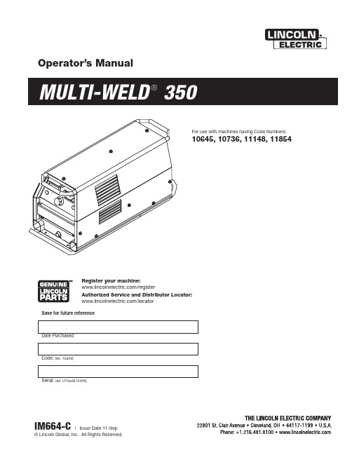
350Operator’s ManualSave for future referenceDate PurchasedCode: (ex: 10859)Serial:(ex: U1060512345)For use with machines having Code Numbers:10645, 10736, 11148, 11854Register your machine: /registerAuthorized Service and Distributor Locator: /locatorSAFETYTECHNICAL SPECIFICATIONS - Multi-Weld 350 (K1735-1)350340350340350340350340MU L TI -S OU RC EM UL T I-SO UR CEMULTI-SOURCE• Converter welding controls are near the arc without Array long control cables, and a receptacle is provided for an optional remote for even closer user output control.Simple• Easy installation with 10 ft. (3m) work clip lead and user preference quick-connect "pigtails" for input and electrode weld cables.• Easy setup with only a few intuitive welding controls and lit displays; including a single Power/Mode switch with Input level light, and a single presettable Output Control with separate digital meters for Amps and Volts, featuring post-weld five second memory display.• Easy Service with quick to replace cable "pig-tails"and "plug-in" assembly modules, including accessible PC boards and interchangeable "plug-n-play" panel instruments.Robust• Capacity is rated for continuous operation at 350 amps in 50°C (122°F) ambient temperature, and can be paralleled to multiply CC mode output rat-ing.• Overload protection is provided with electronic lim-iting of output current, and with thermostat and over-voltage shutdown protection which automati-cally reset.• Outdoor operation protected with sealed control and power electronics compartments, with sealed interconnections, housing "potted" circuit boards, and using "Central-Air" cooling with "Fan-As-Needed" for less dirt intake.• Handling (and mishandling protection) is enhanced with light, but durably designed, aluminum con-struction with front to back, top and bottom, han-dles (also serving as "roll bar" and skid), and a sheetmetal shell attached with 1/4" steel threadedfasteners.The Multi-Weld 350 is provided with a 6-pin remote receptacle to permit use with the 25ft.(7.6 m) K857 or 100ft.(30.4 m) K857-1 Remote Output Control options, or with the LN-25 equipped with the K444-1 Remote Control option. These Remotes have single-turn reso-lution on a Min to Max numbered dialplate.CV MODE WIRE WELDINGThe Converter in CV mode was designed for use with an arc-powered wire feeder like the LN-25. The Converter output is always "hot" when the mode switch is not OFF, so it is recommended that the LN-25 model be equipped with the internal contactor in order to have a "cold" electrode when the gun trigger is released.The CV mode recommended processes are positive (+) polarity wire welding within the output capacity of the Converter, including:CC MODE STICK WELDINGAND GOUGINGThe CC mode recommended processes are positive (+) polarity stick and arc gouging within the output capacity of single, or paralleled, Converters; including: QUICK-CONNECT "PIG-TAILS"The Multi-Weld 350 is factory provided with two 21 in.(53 cm) long 2/0 AWG (70mm2 ) "pig-tail" cables with their 0.5"(13mm) hole lug ends routed through the "INPUT + "(on back) and "ELECTRODE + "(on front) cable channels of the Converter and attached to the bottom-accessed covered cable connection studs. Attach the preferred standard user-provided Quick-connect terminal (such as Lincoln Twist-Mate or Tweco 2-MPC type) to the cut-off end of these cables. Use the female connector on the "ELECTRODE +"cable and the male connector on the "INPUT +" cable.INTER-CONNECTION OF CONVERTERSThe input and electrode cables of the Multi-Weld 350 Converters may be inter-connected in a Multi-Weld System using any combination of Distribution Box(es)(see Figure 1), paralleling ( CC mode only) and "daisy-chaining" (see Figure 2) which best fits thefield application setup within the capacity of the power source supplying the system:Figure 2W W WorW W (-)Work Lead adtoer r Sou ou rc rce s s tu tudMW-35350 0t oo WorkFRONT PANEL CONTROLSThese few instruments are basic to the operation and monitoring of the Converter. They are intuitively laid out so that the panelʼs left side is weld current related, and the right side is weld voltage related:(1) Input Power/ Mode Switch has three positions:Center is OFF which shuts off input power to theConverter.• Neither displays nor output is on if in OFFposition.Left is on for CC (constant current) welding mode.•Only AMPS digital meter is lit displaying thepreset current setting• Output will be on at o.c.v. (open circuit voltage).Right is on for CV (constant voltage) welding mode.• Only VOLTS digital meter is lit displaying thepreset voltage setting• Output will be on at the output voltage setting. (2) Output Control has 3-3/4 turn resolution withslip-clutch to prevent control pot damage.In CC mode it presets AMPS (30-350A range) when not welding, and adjusts actual arc current while welding.In CV mode it presets VOLTS (15-40v range) when not welding, and adjusts actual arc voltage while welding.(3) AMPS Digital Meter is a 3-1/2 digit LED meterwhich displays:Preset Amps in CC mode when not welding."Blank" in CV mode when not welding.Actual Amps while welding in both CC and CV modes.Disconnecting the Remoteʼs plug from this recep-tacle automatically transfers output control back to the panel Output Control (item (2) above).Remote output On/Off switching can also be done thru this Remote Control receptacle. by per-forming the following wiring changes:1. Making sure the input to the Converter isremoved, remove the case wraparound.2. Locate the 4-pin plug (P21) on the backpanel of the control box module, and cut thejumper lead looping from the back of theplug. (Refer to the Wiring Diagram in thismanual.) Insulate the cut lead ends andleave long enough to possibly splice backtogether again at some future time.3. Replace the case wraparound.4. Connect a user-provided remote switchbetween pins D and E of an MS3106A-18-12P plug (Lincoln part no. S12020-27 withS12024-1 cable clamp). See diagrambelow:Pin:Remote Function:A Max. of 10K potB Wiper of 10K potC Min. of 10K potD Output SwitchE Output SwitchF No connection5. Connect this switch plug to the Multi-Weld350 Remote Control Receptacle (10) withswitch opened. Closing the switch activatesthe Converter output.PARALLELED CONVERTERSMulti-Weld 350 converters that are paralleled (see INTER-CONNECTION OF CONVERTERS in the INSTALLATION section) must each be set up in the same manner in order to manage the arc current drawn from each:1) Set to CC mode with CC SLOPE switch set toSTICK/GOUGE.2) Preset Output Controls of both paralleledConverters to ~1/2 desired total Amps.If arc current from each Converter gets too out of bal-ance (primarily a problem if trying to use CV mode) the hotter running Converter could go into current-lim-iting and/or Thermal shutdown (See OVER-TEMPER-ATURE SHUTDOWN in the INSTALLATION section), which might then overload the other, or at least inter-rupt the operatorʼs process. However, no damage will occur to the Converters.REMOTE CONTROL OF PARALLELED CONVERTERS(FOR CC STICK/GOUGE MODE ONLY)Full Range remote control can be accomplished with a separate optional Remote output control (see INSTALLATION section) connected to each Converter. The current contribution of each Converter will depend on its remote output setting.Partial Range remote control can be accomplished with a single Remote Control connected to the output Converter with the input Converter preset with its panel Output Control to below the minimum desired output range. The Remote Control, connected to the output Converter, will control its output to add to the preset level.Remote Output On/Off switching maybe setup for each of the paralleled Converters, but isolated, or double-pole, switches must be used to activate each separately but simultaneously.D-1MAINTENANCED-13. Holding the unit by the front handles, so the back is facing down, shake the loose debris out of the unit. Raking out the heatsink fins may be necessary for jammed debris.4. If necessary, remove the case wraparound cover and using the skid handles to hold upside down carefully dump out any remaining loose debris,or carefully blow out using low pressure air.5. Reassemble the cleaned out Converter by reversing the above steps.DIGITAL METER CALIBRATIONIf calibration of either digital meter is ever necessary,meter calibration adjustment trimmers are provided on the Weld Control PC board inside the Control Module (see Figure 5). Calibration must be done with an Output current load, so meters are displaying Actual (not Preset) values. It is recommended that the cali-bration levels be near the rating plate values, for best accuracy, and compared to "master" meters with bet-ter than 2% accuracy.The accuracy of Actual AMPS meter should be within 3% of the welding amps monitored. The AMPS meter trimmer (R561) is located near the center of the Weld Control PC board just below the VOLTS meter trim-mer (R562). Clockwise rotation of the trimmer adjust-ment screw will decrease the meter reading.The accuracy of Actual VOLTS meter should be within 3% of the welding volts monitored. The VOLTS meter trimmer (R562) is located near the center of the Weld Control PC board just above the AMPS meter trim-mer (R561). Clockwise rotation of the trimmer adjust-ment screw will decrease the meter reading. The "master" voltmeter should be connected as close as possible to the "ELECTRODE +" stud and "WORK-"lead bolt, for best accuracy.MAINTENANCEThe only maintenance which may be required for the Multi-Weld 350 is to clean out any accumulated dirt and debris which could contaminate internal compo-nents, or obstruct proper cooling of the power compo-nents resulting in premature over-temperature shut-down.The recommended cleaning procedure is as follows:1. Be sure to disconnect the Converterʼs input cable to remove its input power.2. Remove the four screws securing the rear louver panel, and remove the panel to expose the cool-ing tunnel heatsinks. (See Figure 4 below):Figure 4This Troubleshooting Guide is provided to help you locate and repair possible machine malfunctions.Simply follow the three-step procedure listed below.Step 1.LOCATE PROBLEM (SYMPTOM).Look under the column labeled “PROBLEM (SYMP-TOMS)”. This column describes possible symptoms that the machine may exhibit. Find the listing that best describes the symptom that the machine is exhibiting.Step 2.POSSIBLE CAUSE.The second column labeled “POSSIBLE CAUSE” lists the obvious external possibilities that may contributeto the machine symptom.Step 3.RECOMMENDED COURSE OF ACTIONThis column provides a course of action for the Possible Cause, generally it states to contact your local Lincoln Authorized Field Service Facility.If you do not understand or are unable to perform the Recommended Course of Action safely, contact your local Lincoln Authorized Field Service Facility.HOW TO USE TROUBLESHOOTING GUIDEService and Repair should only be performed by Lincoln Electric Factory Trained Personnel.Unauthorized repairs performed on this equipment may result in danger to the technician and machine operator and will invalidate your factory warranty. For your safety and to avoid Electrical Shock, please observe all safety notes and precautions detailed throughout this manual.__________________________________________________________________________E : T h i s d i a g r a m i s f o r r e f e r e n c e o n l y . I t m a y n o t b e a c c u r a t e f o r a l l m a c h i n e s c o v e r e d b y t h i s m a n u a l. T h e s p e c i f i c d i a g r a m f o r a p a r t i c u l a r c o d e i s p a s t e d i n s i d e t h e i n e o n o n e o f t h e e n c l o s u r e p a n e l s . I f t h e d i a g r a m i s i l l e g i b l e , w r i t e t o t h e S e r v i c e D e p a r t m e n t f o r a r e p l a c e m e n t . G i v e t h e e q u i p m e n t c o d e n u m b e r .JapaneseChineseKoreanArabicLEIA E COMPREENDA AS INSTRUÇÕES DO FABRICANTE PARA ESTE EQUIPAMENTO E AS PARTES DE USO, E SIGA AS PRÁTICAS DE SEGURANÇA DO EMPREGADOR.JapaneseChineseKoreanArabicREAD AND UNDERSTAND THE MANUFACTURER’S INSTRUCTION FOR THIS EQUIPMENT AND THE CONSUMABLES TO BE USED AND FOLLOW YOUR EMPLOYER’S SAFETY PRACTICES.SE RECOMIENDA LEER Y ENTENDER LAS INSTRUCCIONES DEL FABRICANTE PARA EL USO DE ESTE EQUIPO Y LOS CONSUMIBLES QUE VA A UTILIZAR, SIGA LAS MEDIDAS DE SEGURIDAD DE SU SUPERVISOR.LISEZ ET COMPRENEZ LES INSTRUCTIONS DU FABRICANT EN CE QUI REGARDE CET EQUIPMENT ET LES PRODUITS A ETRE EMPLOYES ET SUIVEZ LES PROCEDURES DE SECURITE DE VOTRE EMPLOYEUR.LESEN SIE UND BEFOLGEN SIE DIE BETRIEBSANLEITUNG DER ANLAGE UND DEN ELEKTRODENEINSATZ DES HER-STELLERS. DIE UNFALLVERHÜTUNGSVORSCHRIFTEN DES ARBEITGEBERS SIND EBENFALLS ZU BEACHTEN.• Sales and Service through Subsidiaries and Distributors Worldwide •Cleveland, Ohio 44117-1199 U.S.A. TEL: 216.481.8100 FAX: 216.486.1751 WEB SITE: 。
荣威350使用技巧

荣威350使用技巧荣威350使用技巧集锦祝您用车安心问题1:不好加挡加挡时,变速箱内主、从动齿轮的外周转速必须同步,才能啮合得上,挂上挡,。
由于低挡主、从动齿轮直径相差大,需要同步时间长,而换挡力度大且猛时会造成同步时间不够,就会感到不好加挡。
应对方法:松油门——轻轻拔入空挡——空挡稍作停顿——用二根挃尖的力度加挡——保持力度不变,同步后会轻松入挡。
空挡滑车后,根据车速需要挂挡时,要空挡给油,再踩离合挂挡。
如此一来换挡将变的轻松自如,新手也能转换自如。
问题2:给油有柴油机声音不少车主都反映说荣威350开起来声音很响感觉像开柴油车,其实这也是不合理驾驶的果.荣威350发动机是低扭矩高转速发动机,最低要1500转,扭力才能满足平地、空载、等速行走时的要求。
低于1500转等速行车、或1800转以下提速时,容易超负荷;2000转以下急给油也会超负荷。
正在加油时油门突然松完或带挡刹车,发动机由牵引变为牵阻,这个突然变化的负荷对350这种可调气门发动机的危害最大,这个大家要足够重视。
发动机超负荷时,显著的特征就是燃烧不完全,并出现柴油机音,异响,;尤其是1500转以下多给油时,声音会更明显。
小三这种小马拉大车外加大脚,致使加速时阻力大增,需要更大的扭力来克服;而进挡后由于发动机低转低扭,反而不易克服加速时增加的阻力。
加挡后,越急于提速,给油越多,发动机越超负荷,异响越大。
所以给油猛的车友最好在换挡前多提高转速,避免加挡后扭力过低出现超负荷。
发动机长时间或经常性超负荷工作,由于燃烧不完全产生大量积碳,在气缸压力过大的情况下,通过火塞环背隙、火塞环口间隙进入机体,使机油性质变劣,润滑作用下降;并在火塞上的环槽内及气门导管内沉积,有可能遭成火塞环卡住、气门口闭合不严,导致发动机功率下降、异响等;而要除去这些地方的积碳,只有拆机,手工去刮,其危害可想而知。
以上情况证明加挡前提速要比加挡后提速省油、省车、无异响。
应对方法:起步时,发动机1300转以下时使用半离合;空载、平地、不开空调条件下,2500转以上加挡;上坡或满载或开了空调情况下,2800转以上加挡;加挡动作慢的、坡度大的、空调满载、超车时、开车猛的,转速还要多提高点;下坡时转速也要2200转以上加挡。
英威腾 Goodrive350 用户手册说明书

Goodrive350 系列变频器Auto Station可编程扩展卡安全注意事项安装和操作本扩展卡的工作人员必须经过专业的电气培训和安全知识培训并且考试合格,已经熟悉本扩展卡的安装、调试、投入运行以及维护保养的步骤和要求,并能避免产生各种紧急情况。
在安装、拆除和操作扩展卡前,请仔细阅读本说明书和变频器说明书的安全注意事项章节,确保在安全下操作。
如因用户未遵守本说明书和变频器说明书的安全注意事项而造成的伤害和设备损坏,本公司将不承担责任。
●安装或拆除本扩展卡时需要拆开变频器的机壳,因此必须要完全断开变频器所有的电源输入,并确保设备内部电压已安全,方法请见变频器说明书。
如果不遵守该项要求,可能会造成严重的人身伤害,甚至死亡。
●存放扩展卡时,必须将之放于具防尘、防潮、不受电击以及没有机械压力的地方。
●扩展卡对静电敏感,在相关操作时,必须做好防静电措施,以免损坏元器件。
●在安装本扩展卡时,一定要拧紧螺钉,确保不松动及接地正常。
目录安全注意事项 (i)目录.......................................................................................................................................... i i 第1章产品确认 .. (1)第2章产品概述 (2)2.1 基本介绍 (2)2.2 型号说明 (2)2.3 端子排布说明 (3)2.4 卡状态指示 (5)第3章二次开发平台 (6)3.1 上位机Auto Station开发环境介绍 (6)3.2 PLC程序下载接口说明 (6)3.3 Auto Station编程软件的使用说明 (7)第4章Auto Station编程接口和定义 (11)4.1 Auto Station编程接口导入与导出 (11)4.2 开关量输入和输出编程接口 (13)4.3 模拟量输入和模拟量输出编程接口 (16)4.4 控制命令和功能指令编程接口 (17)4.5 功能参数设定编程接口 (20)4.6 功能参数查看和变频器状态查看接口 (21)4.7 PLC自定义故障(当前设计10个)接口 (24)4.8 写入组编程接口 (25)4.9 监控组编程接口 (25)4.10 RUN/STOP拨码开关及PLC卡运行状态说明 (26)4.11 PLC卡与DP/CANopen/PN通信通道 (27)4.12 485通讯及用户数据掉电存储功能 (32)第5章编程举例说明 (33)5.1 可编程扩展卡开关量输入输出端子应用 (33)5.2 端子控制运行/故障应用 (33)5.3 多段速设定与运行应用 (34)5.4 485通信应用 (36)附录A 可编程扩展卡与变频器交互D元件一览表 (38)附录B 可编程扩展卡功能码组(P27组)一览表 (48)在接收到可编程扩展卡产品时请确认以下内容:●检查可编程扩展卡是否有损坏。
荣威RX5娱乐导航手册

蓝牙电话 ..................................................... 55
使用须知 ..................................................................................................55 蓝牙匹配及连接 ........................................................................................56 电话菜单 ..................................................................................................57 拨号盘 .....................................................................................................58 通讯录 .....................................................................................................59 通话记录 ..................................................................................................60 连接 .........................................................................................................61 拨打电话 ..................................................................................................61 来电 .........................................................................................................65
林肯电子POWER MIG350MP操作手册说明书

POWER MIG ®350MPʼS MANUALIM859May, 2012Safety Depends on YouLincoln arc welding and cutting equipment is designed and built with safety in mind. However,your overall safety can be increased by proper installation ... and thoughtful operation on your part. DO NOT INSTALL,OPERATE OR REPAIR THIS EQUIPMENT WITHOUT READ-ING THIS MANUAL AND THE SAFETY PRECAUTIONS CON-TAINED THROUGHOUT.And,most importantly, think before you act and be careful.For use with machine Code Numbers: 11147Copyright © Lincoln Global Inc.vvRead this Operators Manual completely before attempting to use this equipment. Save this manual and keep it handy for quick reference. Pay particular attention to the safety instructions we have provided for your protection.The level of seriousness to be applied to each is explained below:TECHNICAL SPECIFICATIONS – POWER MIG®350MP®350MPGUN HANDLESET SCREWSET SCREW INSULATION TUBEFEEDR END CABLE HANDLECLAMPING SCREWGUN TUBE9/16 (14.3mm)GAS DIFFUSERNOZZLE INSULATION GAS NOZZLEMOLDED GAS PLUGLINER ASSEMBLY (LINER BUSHING TO BE SEATED TIGHT AGIANST BRASS CABLE CONNECTOR)BRASS CABLE CONNECTORLINER TRIM LENGTHFIGURE A.3FIGURE A.45. MULTI-PROCESS PANEL - This panel enables selection of weld modes as well as adjustment of certain weld parameters within each weld mode.The eight discrete LED ʼs are used to identify which selec-tion will be shown on the display. The possible selections are:• Weld Mode (Process selection choices)• Preflow / Postflow • Run-In • Start • Arc Control • Crater • Burnback • SpotOnly one LED will be illuminated at any time. The Weld Mode attribute will always be a valid selection (the other attributes may not be available in all processes).5A. SELECT Toggle Switch• This switch toggles through the 8 selections detailed above the switch.• A red LED is located next to each possible selection and is illuminated when that choice can be changed.5B. Display Meter• This meter displays the active weld mode (a set of weld parameters that have been determined to pro-vide the recommended results for a particular welding process) when the “Weld Mode” LED is illuminated or when any one of the other seven LED ʼs is illuminated the meter indicates what value that welding parame-ter has been set to.5C. SET Toggle Switch• This switch adjusts (up or down) the value shown on the display meter. When the WELD MODE LED is illu-minated, this switch is changing the weld mode of the machine. The most commonly used modes are dis-played in the chart on the right half of the Multi-Process Panel.If the LED next to a weld parameter (Preflow/Postflow,Run-In, Start, etc.) is illuminated, the SET switch will adjust the setting of that specific weld parameter. The setting is shown on the display meter.6. ON/OFF POWER SWITCH}Choice of weld parameters that can be plete descriptions of each parameter are found later in this section.2. VOLT / TRIM METER -This meter displays either the voltage or trim value depending on the status of the machine. Located below the display is the text "Volts" and "Trim." An LED light is illuminated to the left of one of these in order to indicate the units of the value displayed in the meter.CV Processes• Prior to GMAW and FCAW operation, the meter displays the desired preset Voltage value.• Prior to synergic GMAW-P and GMAW-PP oper-ation, the meter displays the desired preset Trim value. Trim adjusts the synergic default voltage as a percentage of that voltage. A trim value of 1is the default and results in the recommended voltage setting for a given wire feed speed.Adjusting trim to a value of .95, adjusts the volt-age to 95% of the recommended voltage.• During Welding, the meter displays actual aver-age volts.• After welding, the meter holds the actual voltage value for 5 seconds. During this time , the display is blinking to indicate that the machine is in the "Hold" period. Output adjustment while in the "Hold" period results in the "prior to operation"characteristics stated above.• After the 5 second "Hold" period, the meter dis-plays the set Voltage (GMAW, FCAW) or Trim (GMAW-P) value.CC Processes• The meter displays the status of the output.• When output is enabled, the meter will display "ON."• When there is no output, the meter will display "OFF."3. OUTPUT CONTROLS - The POWER MIG ®350MP has 2encoder knobs to adjust weld parameters.• Each encoder changes the displayed value of the meter located directly above that encoder.• In CC-GTAW modes, the left encoder sets the maxi-mum welding current. Full depression of a foot or hand amptrol results in the preset level of current.• In CC-Stick and CC-GTAW, the right encoder activates and de-activates the output. Turning the encoder clock-wise enables the output if not using a remote trigger device. To de-energize the output, turn the encoder counter-clockwise. The display above will indicate the "ON" or "OFF" status of the output.4. THERMAL - This status light illuminates when the power source has been driven into thermal overload.5. Loosen the socket head cap screw that holds the connector bar against the gun bushing.Important: Do not attempt to completely remove the socket head cap screw.6. Remove the outer wire guide, and push the gun bushing out of the wire drive. Because of the pre-cision fit, light tapping may be required to remove the gun bushing.7. Disconnect the shielding gas hose from the gun bushing, if required.8. Connect the shielding gas hose to the new gun bushing, if required.9. Rotate the gun bushing until the thumb screw hole aligns with the thumb screw hole in the feed plate.Slide the gun receiver bushing into the wire drive and verify the thumb screw holes are aligned.10. Tighten the socket head cap screw.11. Insert the welding gun into the gun bushing andtighten the thumb screw.AVOIDING WIRE FEEDING PROBLEMSWire feeding problems can be avoided by observing the following gun handling procedures:a.Do not kink or pull cable around sharp corners.b.Keep the gun cable as straight as possible when welding or loading electrode through cable.c.Do not allow dolly wheels or trucks to run over cables.d.Keep cable clean by following maintenance instruc-tions.e only clean, rust-free electrode. Lincoln elec-trodes have proper surface lubrication.f.Replace the contact tip when the arc starts to become unstable or the contact tip end is fused or deformed.g.Keep wire reel spindle brake tension to the mini-mum required to prevent excess reel over-travel which may cause wire “loop-offs” from the coil.e proper drive rolls and wire drive/idle roll pres-sure for wire size and type being used.SPECIAL WELDING PROCESSES AVAILABLE ON THE POWER MIG ®350MPPULSE WELDING (GMAW-P)The pulsed-arc process is, by definition, a spray trans-fer process wherein spray transfer occurs in pulses at regularly spaced intervals. In the time between pulses,the welding current is reduced and no metal transfer occurs.Pulsed-arc transfer is obtained by operating a power source between low and high current levels. The high current level or “pulse” forces an electrode drop to the workpiece. The low current level or “background”maintains the arc between pulses. (See Figure B.5).Pulsed MIG is an advanced form of welding that takes the best of all the other forms of transfer while minimiz-ing or eliminating their disadvantages. Unlike short cir-cuit, pulsed MIG does not create spatter or run the risk of cold lapping. The welding positions in pulsed MIG are not limited as they are with globular or spray and its wire use is definitely more efficient. Unlike the spray arc process, pulsing offers controlled heat input that allows better welding on thin materials, lower wire feed speeds and leads to less distortion and improved overall quality and appearance. This is especially important with stain-less, nickel and other alloys that are sensitive to heat input.In GMAW-P mode,arc control adjusts the background current and frequency of the wave. When arc control goes up, the frequency increases thus increasing the droplet transfer rate.POWER MODE™The Power Mode™ process was developed by Lincoln to maintain a stable and smooth arc at low procedure settings which are needed to weld thin metal without pop-outs or burning-through. For Aluminum welding, it provides excellent control and the ability to maintain constant arc length. This results in improved welding performance in two primary types of applications.• Short Arc MIG at low procedure settings.• Aluminum MIG welding.Power Mode™ is a method of high speed regulation of the output power whenever an arc is established. It provides a fast response to changes in the arc. The higher the Power Mode™ Setting, the longer the arc. If a welding procedure is not established, the best way to determine the Power Mode™ Setting is by experi-mentation until the desired output result is estab-lished.In the Power Mode™ two variables need to be set:• Wire Feed Speed• Power Mode TrimSetting up a Power Mode™ procedure is similar to setting a CV MIG procedure. Select a shielding gas appropriate for a short arc process.• For steel, use 75/25 Ar/CO2shield gas.• For Stainless, select a Helium blend Tri-Mix.• For Aluminum, use 100% Ar.Start by setting the wire feed speed based upon mate-rial thickness and appropriate travel speed. Then adjust the Volts/Trim knob as follows:• For steel, listen for the traditional “frying egg”sound of a good short-arc MIG procedure to know you have the process set correctly.• For aluminum, simply adjust the Volts/Trim knob until the desired arc length is obtained.Note the Volts/Trim display is simply a relative number and DOES NOT correspond to voltage.TIG WELDING:The basic sequence of operation.1. Use SET toggle to select GTAW (Mode 03)2. Adjust desired amperage using WFS/AMPS CON-TROL. If using an optional foot or hand Amptrol to control current this setting will be maximum when the Amptrol is fully depressed or extended.3. Energize output with either a remote trigger deviceplugged into the remote connector, or rotate VOLTS/TRIM CONTROL clockwise.4. Touch tungsten to work piece and lift off to establish the arc.5. START can be set by using the SELECT toggle. Use the WFS/AMPS Control to set the respective start current.a.Choose the correct size contact tip for the elec-trode being used (wire size is stenciled on the side of the contact tip) and screw it snugly into the gas diffuser.b.Be sure the nozzle insulator is fully screwed ontothe gun tube and does not block the gas holes in the diffuser. (NOTE: Insulator is not required when using the optional fixed gas nozzles.)c.Slip the appropriate gas nozzle onto the nozzleinsulator. Adjustable gas nozzles are available witha .62” (15.9 mm) or .50” (12.7 mm) I.D., and in bothstandard (flush) and recessed design. The proper nozzle should be selected based on the welding application. Different length fixed nozzles are also available to fit 350MP and 400 amp gun tubes to allow either spray or short-circuiting transfer weld-ing.Choose the gas nozzle as appropriate for the GMAW process to be used. Typically, the contact tip end should be flush to .12” (3.1 mm) extended for the short-circuiting transfer process and .12”(3.1 mm) recessed for spray transfer. For theOutershield (FCAW) process, 1/8” (3 mm) recess is recommended.GUN TUBES AND NOZZLESa.Replace worn contact tips as required.b.Remove spatter from inside of gas nozzle and fromtip after each 10 minutes of arc time or as required. GUN CABLE CLEANINGTo help prevent feeding problems, clean cable liner after using approximately 350MP pounds (136 kg) of electrode. Remove the cable from the wire feeder and lay it out straight on the floor. Remove the contact tip from the gun. Using an air hose and only partial pres-sure, gently blow out the cable liner from the gas dif-fuser end.GUN HANDLESET SCREWSET SCREW INSULATION TUBEFEEDR END CABLE HANDLECLAMPING SCREWGUN TUBE9/16 (14.3mm)GAS DIFFUSERNOZZLE INSULATION GAS NOZZLEMOLDED GAS PLUGLINER ASSEMBLY (LINER BUSHING TO BE SEATED TIGHT AGIANST BRASS CABLE CONNECTOR)BRASS CABLE CONNECTORLINER TRIM LENGTHFIGURE D.1This Troubleshooting Guide is provided to help youlocate and repair possible machine malfunctions.Simply follow the three-step procedure listed below.Step 1.LOCATE PROBLEM (SYMPTOM).Look under the column labeled “PROBLEM (SYMP-TOMS)”. This column describes possible symptomsthat the machine may exhibit. Find the listing thatbest describes the symptom that the machine isexhibiting.Step 2.POSSIBLE CAUSE.The second column labeled “POSSIBLE CAUSE” lists the obvious external possibilities that may contributeto the machine symptom. Step 3.RECOMMENDED COURSE OF ACTION This column provides a course of action for the Possible Cause, generally it states to contact your local Lincoln Authorized Field Service Facility.If you do not understand or are unable to perform the Recommended Course of Action safely, contact your local Lincoln Authorized Field Service Facility.Service and Repair should only be performed by Lincoln Electric Factory Trained Personnel.Unauthorized repairs performed on this equipment may result in danger to the technician and machine operator and will invalidate your factory warranty. For your safety and to avoid Electrical Shock, please observe all safety notes and precautions detailed throughout this manual.__________________________________________________________________________PUSH PULL WIRE FEEDING PROBLEMSSTALL FACTOR- an adjustment on the POWER MIG®350MP that allows the welder to adjust the maximum amount of power going to the rear drive motor. The purpose is to send only enough power to the rear drive motor to pull the wire off the spool and get the wire up the torch liner.STALL FACTOR NUMBER ADJUSTMENT1. Turn the POWER MIG®350MP off.2. Hold the Push-Pull Torch trigger in and turn the power back on. Continue to hold the trigger in while machinepowers up.3. Once the machine displays "SF" in the left display and a number 5 to 35 in the right display the trigger can bereleased.4. Use the volts / trim knob to adjust the Stall Factor Number.5. Once the Stall Factor Number is adjusted push the select switch up.6. The display should scroll the word “SAVEd” if the number was changed. The display will scroll "no CHANGE" ifthe SF number was not changed.7. The machine should automatically switch back to normal operation after it is done saving the SF number. POWER MIG®350MP“CLEAR ALL” PROCEDURE1. Hold “select” switch up while powering up machine.2. Release “select” switch when displays show “Press Pin”.3. Turn the right “encoder knob” until displays show “Clr All”.4. Toggle the “select” switch up and release.5. Machine will reset itself.JapaneseChineseKoreanArabicREAD AND UNDERSTAND THE MANUFACTURER’S INSTRUCTION FOR THIS EQUIPMENT AND THE CONSUMABLES TO BE USED AND FOLLOW YOUR EMPLOYER’S SAFETY PRACTICES.SE RECOMIENDA LEER Y ENTENDER LAS INSTRUCCIONES DEL FABRICANTE PARA EL USO DE ESTE EQUIPO Y LOS CONSUMIBLES QUE VA A UTILIZAR, SIGA LAS MEDIDAS DE SEGURIDAD DE SU SUPERVISOR.LISEZ ET COMPRENEZ LES INSTRUCTIONS DU FABRICANT EN CE QUI REGARDE CET EQUIPMENT ET LES PRODUITS A ETRE EMPLOYES ET SUIVEZ LES PROCEDURES DE SECURITE DE VOTRE EMPLOYEUR.LESEN SIE UND BEFOLGEN SIE DIE BETRIEBSANLEITUNG DER ANLAGE UND DEN ELEKTRODENEINSATZ DES HER-STELLERS. DIE UNFALLVERHÜTUNGSVORSCHRIFTEN DES ARBEITGEBERS SIND EBENFALLS ZU BEACHTEN.JapaneseChineseKoreanArabicLEIA E COMPREENDA AS INSTRUÇÕES DO FABRICANTE PARA ESTE EQUIPAMENTO E AS PARTES DE USO, E SIGA AS PRÁTICAS DE SEGURANÇA DO EMPREGADOR.。