毕业设计外文翻译原文.
毕业论文(设计)外文文献翻译及原文

金融体制、融资约束与投资——来自OECD的实证分析R.SemenovDepartment of Economics,University of Nijmegen,Nijmegen(荷兰内梅亨大学,经济学院)这篇论文考查了OECD的11个国家中现金流量对企业投资的影响.我们发现不同国家之间投资对企业内部可获取资金的敏感性具有显著差异,并且银企之间具有明显的紧密关系的国家的敏感性比银企之间具有公平关系的国家的低.同时,我们发现融资约束与整体金融发展指标不存在关系.我们的结论与资本市场信息和激励问题对企业投资具有重要作用这种观点一致,并且紧密的银企关系会减少这些问题从而增加企业获取外部融资的渠道。
一、引言各个国家的企业在显著不同的金融体制下运行。
金融发展水平的差别(例如,相对GDP的信用额度和相对GDP的相应股票市场的资本化程度),在所有者和管理者关系、企业和债权人的模式中,企业控制的市场活动水平可以很好地被记录.在完美资本市场,对于具有正的净现值投资机会的企业将一直获得资金。
然而,经济理论表明市场摩擦,诸如信息不对称和激励问题会使获得外部资本更加昂贵,并且具有盈利投资机会的企业不一定能够获取所需资本.这表明融资要素,例如内部产生资金数量、新债务和权益的可得性,共同决定了企业的投资决策.现今已经有大量考查外部资金可得性对投资决策的影响的实证资料(可参考,例如Fazzari(1998)、 Hoshi(1991)、 Chapman(1996)、Samuel(1998)).大多数研究结果表明金融变量例如现金流量有助于解释企业的投资水平。
这项研究结果解释表明企业投资受限于外部资金的可得性。
很多模型强调运行正常的金融中介和金融市场有助于改善信息不对称和交易成本,减缓不对称问题,从而促使储蓄资金投着长期和高回报的项目,并且提高资源的有效配置(参看Levine(1997)的评论文章)。
因而我们预期用于更加发达的金融体制的国家的企业将更容易获得外部融资.几位学者已经指出建立企业和金融中介机构可进一步缓解金融市场摩擦。
毕业设计外文翻译译文

1 工程概论1.1 工程专业1.2 工业和技术1.3 现代制造业工程专业1 工程行业是历史上最古老的行业之一。
如果没有在广阔工程领域中应用的那些技术,我们现在的文明绝不会前进。
第一位把岩石凿削成箭和矛的工具匠是现代机械工程师的鼻祖。
那些发现地球上的金属并找到冶炼和使用金属的方法的工匠们是采矿和冶金工程师的先祖。
那些发明了灌溉系统并建造了远古世纪非凡的建筑物的技师是他们那个时代的土木工程师。
2 工程一般被定义为理论科学的实际应用,例如物理和数学。
许多早期的工程设计分支不是基于科学而是经验信息,这些经验信息取决于观察和经历,而不是理论知识。
这是一个倾斜面实际应用的例子,虽然这个概念没有被确切的理解,但是它可以被量化或者数字化的表达出来。
3 从16、17世纪当代初期,量化就已经成为科学知识大爆炸的首要原因之一。
另外一个重要因素是实验法验证理论的发展。
量化包含了把来源于实验的数据和信息转变成确切的数学术语。
这更加强调了数学是现代工程学的语言。
4 从19世纪开始,它的结果的实际而科学的应用已经逐步上升。
机械工程师现在有精确的能力去计算来源于许多不同机构之间错综复杂的相互作用的机械优势。
他拥有能一起工作的既新型又强硬的材料和巨大的新能源。
工业革命开始于使用水和蒸汽一起工作。
从此使用电、汽油和其他能源作动力的机器变得如此广泛以至于它们承担了世界上很大比例的工作。
5 科学知识迅速膨胀的结果之一就是科学和工程专业的数量的增加。
到19世纪末不仅机械、土木、矿业、冶金工程被建立而且更新的化学和电气工程专业出现了。
这种膨胀现象一直持续到现在。
我们现在拥有了核能、石油、航天航空空间以及电气工程等。
每种工程领域之内都有细分。
6 例如,土木工程自身领域之内有如下细分:涉及永久性结构的建筑工程、涉及水或其他液体流动与控制系统的水利工程、涉及供水、净化、排水系统的研究的环境工程。
机械工程主要的细分是工业工程,它涉及的是错综复杂的机械系统,这些系统是工业上的,而非单独的机器。
毕业设计外文翻译_英文版
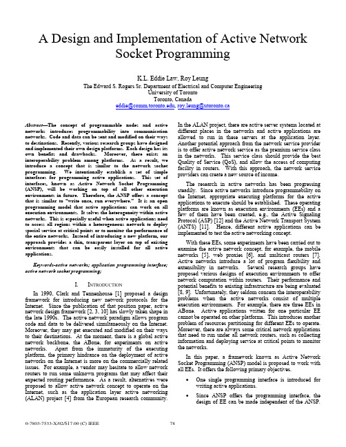
A Design and Implementation of Active NetworkSocket ProgrammingK.L. Eddie Law, Roy LeungThe Edward S. Rogers Sr. Department of Electrical and Computer EngineeringUniversity of TorontoToronto, Canadaeddie@, roy.leung@utoronto.caAbstract—The concept of programmable nodes and active networks introduces programmability into communication networks. Code and data can be sent and modified on their ways to destinations. Recently, various research groups have designed and implemented their own design platforms. Each design has its own benefits and drawbacks. Moreover, there exists an interoperability problem among platforms. As a result, we introduce a concept that is similar to the network socket programming. We intentionally establish a set of simple interfaces for programming active applications. This set of interfaces, known as Active Network Socket Programming (ANSP), will be working on top of all other execution environments in future. Therefore, the ANSP offers a concept that is similar to “write once, run everywhere.” It is an open programming model that active applications can work on all execution environments. It solves the heterogeneity within active networks. This is especially useful when active applications need to access all regions within a heterogeneous network to deploy special service at critical points or to monitor the performance of the entire networks. Instead of introducing a new platform, our approach provides a thin, transparent layer on top of existing environments that can be easily installed for all active applications.Keywords-active networks; application programming interface; active network socket programming;I. I NTRODUCTIONIn 1990, Clark and Tennenhouse [1] proposed a design framework for introducing new network protocols for the Internet. Since the publication of that position paper, active network design framework [2, 3, 10] has slowly taken shape in the late 1990s. The active network paradigm allows program code and data to be delivered simultaneously on the Internet. Moreover, they may get executed and modified on their ways to their destinations. At the moment, there is a global active network backbone, the ABone, for experiments on active networks. Apart from the immaturity of the executing platform, the primary hindrance on the deployment of active networks on the Internet is more on the commercially related issues. For example, a vendor may hesitate to allow network routers to run some unknown programs that may affect their expected routing performance. As a result, alternatives were proposed to allow active network concept to operate on the Internet, such as the application layer active networking (ALAN) project [4] from the European research community. In the ALAN project, there are active server systems located at different places in the networks and active applications are allowed to run in these servers at the application layer. Another potential approach from the network service provider is to offer active network service as the premium service class in the networks. This service class should provide the best Quality of Service (QoS), and allow the access of computing facility in routers. With this approach, the network service providers can create a new source of income.The research in active networks has been progressing steadily. Since active networks introduce programmability on the Internet, appropriate executing platforms for the active applications to execute should be established. These operating platforms are known as execution environments (EEs) and a few of them have been created, e.g., the Active Signaling Protocol (ASP) [12] and the Active Network Transport System (ANTS) [11]. Hence, different active applications can be implemented to test the active networking concept.With these EEs, some experiments have been carried out to examine the active network concept, for example, the mobile networks [5], web proxies [6], and multicast routers [7]. Active networks introduce a lot of program flexibility and extensibility in networks. Several research groups have proposed various designs of execution environments to offer network computation within routers. Their performance and potential benefits to existing infrastructure are being evaluated [8, 9]. Unfortunately, they seldom concern the interoperability problems when the active networks consist of multiple execution environments. For example, there are three EEs in ABone. Active applications written for one particular EE cannot be operated on other platforms. This introduces another problem of resources partitioning for different EEs to operate. Moreover, there are always some critical network applications that need to run under all network routers, such as collecting information and deploying service at critical points to monitor the networks.In this paper, a framework known as Active Network Socket Programming (ANSP) model is proposed to work with all EEs. It offers the following primary objectives.• One single programming interface is introduced for writing active applications.• Since ANSP offers the programming interface, the design of EE can be made independent of the ANSP.This enables a transparency in developing andenhancing future execution environments.• ANSP addresses the interoperability issues among different execution environments.• Through the design of ANSP, the pros and cons of different EEs will be gained. This may help design abetter EE with improved performance in future.The primary objective of the ANSP is to enable all active applications that are written in ANSP can operate in the ABone testbed . While the proposed ANSP framework is essential in unifying the network environments, we believe that the availability of different environments is beneficial in the development of a better execution environment in future. ANSP is not intended to replace all existing environments, but to enable the studies of new network services which are orthogonal to the designs of execution environments. Therefore, ANSP is designed to be a thin and transparent layer on top of all execution environments. Currently, its deployment relies on automatic code loading with the underlying environments. As a result, the deployment of ANSP at a router is optional and does not require any change to the execution environments.II. D ESIGN I SSUES ON ANSPThe ANSP unifies existing programming interfaces among all EEs. Conceptually, the design of ANSP is similar to the middleware design that offers proper translation mechanisms to different EEs. The provisioning of a unified interface is only one part of the whole ANSP platform. There are many other issues that need to be considered. Apart from translating a set of programming interfaces to other executable calls in different EEs, there are other design issues that should be covered, e.g., • a unified thread library handles thread operations regardless of the thread libraries used in the EEs;• a global soft-store allows information sharing among capsules that may execute over different environmentsat a given router;• a unified addressing scheme used across different environments; more importantly, a routing informationexchange mechanism should be designed across EEs toobtain a global view of the unified networks;• a programming model that should be independent to any programming languages in active networks;• and finally, a translation mechanism to hide the heterogeneity of capsule header structures.A. Heterogeneity in programming modelEach execution environment provides various abstractions for its services and resources in the form of program calls. The model consists of a set of well-defined components, each of them has its own programming interfaces. For the abstractions, capsule-based programming model [10] is the most popular design in active networks. It is used in ANTS [11] and ASP [12], and they are being supported in ABone. Although they are developed based on the same capsule model, their respective components and interfaces are different. Therefore, programs written in one EE cannot run in anther EE. The conceptual views of the programming models in ANTS and ASP are shown in Figure 1.There are three distinct components in ANTS: application, capsule, and execution environment. There exist user interfaces for the active applications at only the source and destination routers. Then the users can specify their customized actions to the networks. According to the program function, the applications send one or more capsules to carry out the operations. Both applications and capsules operate on top of an execution environment that exports an interface to its internal programming resources. Capsule executes its program at each router it has visited. When it arrives at its destination, the application at destination may either reply it with another capsule or presents this arrival event to the user. One drawback with ANTS is that it only allows “bootstrap” application.Figure 1. Programming Models in ASP and ANTS.In contrast, ASP does not limit its users to run “bootstrap” applications. Its program interfaces are different from ANTS, but there are also has three components in ASP: application client, environment, and AAContext. The application client can run on active or non-active host. It can start an active application by simply sending a request message to the EE. The client presents information to users and allows its users to trigger actions at a nearby active router. AAContext is the core of the network service and its specification is divided into two parts. One part specifies its actions at its source and destination routers. Its role is similar to that of the application in ANTS, except that it does not provide a direct interface with the user. The other part defines its actions when it runs inside the active networks and it is similar to the functional behaviors of a capsule in ANTS.In order to deal with the heterogeneity of these two models, ANSP needs to introduce a new set of programming interfaces and map its interfaces and execution model to those within the routers’ EEs.B. Unified Thread LibraryEach execution environment must ensure the isolation of instance executions, so they do not affect each other or accessThe authors appreciate the Nortel Institute for Telecommunications (NIT) at the University of Toronto to allow them to access the computing facilitiesothers’ information. There are various ways to enforce the access control. One simple way is to have one virtual machine for one instance of active applications. This relies on the security design in the virtual machines to isolate services. ANTS is one example that is using this method. Nevertheless, the use of multiple virtual machines requires relatively large amount of resources and may be inefficient in some cases. Therefore, certain environments, such as ASP, allow network services to run within a virtual machine but restrict the use of their services to a limited set of libraries in their packages. For instance, ASP provides its thread library to enforce access control. Because of the differences in these types of thread mechanism, ANSP devises a new thread library to allow uniform accesses to different thread mechanisms.C. Soft-StoreSoft-store allows capsule to insert and retrieve information at a router, thus allowing more than one capsules to exchange information within a network. However, problem arises when a network service can execute under different environments within a router. The problem occurs especially when a network service inserts its soft-store information in one environment and retrieves its data at a later time in another environment at the same router. Due to the fact that execution environments are not allowed to exchange information, the network service cannot retrieve its previous data. Therefore, our ANSP framework needs to take into account of this problem and provides soft-store mechanism that allows universal access of its data at each router.D. Global View of a Unified NetworkWhen an active application is written with ANSP, it can execute on different environment seamlessly. The previously smaller and partitioned networks based on different EEs can now be merging into one large active network. It is then necessary to advise the network topology across the networks. However, different execution environments have different addressing schemes and proprietary routing protocols. In order to merge these partitions together, ANSP must provide a new unified addressing scheme. This new scheme should be interpretable by any environments through appropriate translations with the ANSP. Upon defining the new addressing scheme, a new routing protocol should be designed to operate among environments to exchange topology information. This allows each environment in a network to have a complete view of its network topology.E. Language-Independent ModelExecution environment can be programmed in any programming language. One of the most commonly used languages is Java [13] due to its dynamic code loading capability. In fact, both ANTS and ASP are developed in Java. Nevertheless, the active network architecture shown in Figure 2 does not restrict the use of additional environments that are developed in other languages. For instance, the active network daemon, anted, in Abone provides a workspace to execute multiple execution environments within a router. PLAN, for example, is implemented in Ocaml that will be deployable on ABone in future. Although the current active network is designed to deploy multiple environments that can be in any programming languages, there lacks the tool to allow active applications to run seamlessly upon these environments. Hence, one of the issues that ANSP needs to address is to design a programming model that can work with different programming languages. Although our current prototype only considers ANTS and ASP in its design, PLAN will be the next target to address the programming language issue and to improve the design of ANSP.Figure 2. ANSP Framework Model.F. Heterogeneity of Capsule Header StructureThe structures of the capsule headers are different in different EEs. They carries capsule-related information, for example, the capsule types, sources and destinations. This information is important when certain decision needs to be made within its target environment. A unified model should allow its program code to be executed on different environments. However, the capsule header prevents different environments to interpret its information successfully. Therefore, ANSP should carry out appropriate translation to the header information before the target environment receives this capsule.III. ANSP P ROGRAMMING M ODELWe have outlined the design issues encountered with the ANSP. In the following, the design of the programming model in ANSP will be discussed. This proposed framework provides a set of unified programming interfaces that allows active applications to work on all execution environments. The framework is shown in Figure 2. It is composed of two layers integrated within the active network architecture. These two layers can operate independently without the other layer. The upper layer provides a unified programming model to active applications. The lower layer provides appropriate translation procedure to the ANSP applications when it is processed by different environments. This service is necessary because each environment has its own header definition.The ANSP framework provides a set of programming calls which are abstractions of ANSP services and resources. A capsule-based model is used for ANSP, and it is currently extended to map to other capsule-based models used in ANTSand ASP. The mapping possibility to other models remains as our future works. Hence, the mapping technique in ANSP allows any ANSP applications to access the same programming resources in different environments through a single set of interfaces. The mapping has to be done in a consistent and transparent manner. Therefore, the ANSP appears as an execution environment that provides a complete set of functionalities to active applications. While in fact, it is an overlay structure that makes use of the services provided from the underlying environments. In the following, the high-level functional descriptions of the ANSP model are described. Then, the implementations will be discussed. The ANSP programming model is based upon the interactions between four components: application client , application stub , capsule , and active service base.Figure 3. Information Flow with the ANSP.•Application Client : In a typical scenario, an active application requires some means to present information to its users, e.g., the state of the networks. A graphical user interface (GUI) is designed to operate with the application client if the ANSP runs on a non-active host.•Application Stub : When an application starts, it activates the application client to create a new instance of application stub at its near-by active node. There are two responsibilities for the application stub. One of them is to receive users’ instructions from the application client. Another one is to receive incoming capsules from networks and to perform appropriate actions. Typically, there are two types of actions, thatare, to reply or relay in capsules through the networks, or to notify the users regarding the incoming capsule. •Capsule : An active application may contain several capsule types. Each of them carries program code (also referred to as forwarding routine). Since the application defines a protocol to specify the interactions among capsules as well as the application stubs. Every capsule executes its forwarding routine at each router it visits along the path between the source and destination.•Active Service Base : An active service base is designed to export routers’ environments’ services and execute program calls from application stubs and capsules from different EEs. The base is loaded automatically at each router whenever a capsule arrives.The interactions among components within ANSP are shown in Figure 3. The designs of some key components in the ANSP will be discussed in the following subsections. A. Capsule (ANSPCapsule)ANSPXdr decode () ANSPXdr encode () int length ()Boolean execute ()New types of capsule are created by extending the abstract class ANSPCapsule . New extensions are required to define their own forwarding routines as well as their serialization procedures. These methods are indicated below:The execution of a capsule in ANSP is listed below. It is similar to the process in ANTS.1. A capsule is in serial binary representation before it issent to the network. When an active router receives a byte sequence, it invokes decode() to convert the sequence into a capsule. 2. The router invokes the forwarding routine of thecapsule, execute(). 3. When the capsule has finished its job and forwardsitself to its next hop by calling send(), this call implicitly invokes encode() to convert the capsule into a new serial byte representation. length() isused inside the call of encode() to determine the length of the resulting byte sequence. ANSP provides a XDR library called ANSPXdr to ease the jobs of encoding and decoding.B. Active Service Base (ANSPBase)In an active node, the Active Service Base provides a unified interface to export the available resources in EEs for the rest of the ANSP components. The services may include thread management, node query, and soft-store operation, as shown in Table 1.TABLE I. ACTIVE SERVICE BASE FUNCTION CALLSFunction Definition Descriptionboolean send (Capsule, Address) Transmit a capsule towards its destination using the routing table of theunderlying environment.ANSPAddress getLocalHost () Return address of the local host as an ANSPAddress structure. This isuseful when a capsule wants to check its current location.boolean isLocal (ANSPAddress) Return true if its input argument matches the local host’s address andreturn false otherwise.createThread () Create a new thread that is a class ofANSPThreadInterface (discussed later in Section VIA “Unified Thread Abstraction”).putSStore (key, Object) Object getSStore (key) removeSStore (key)The soft-store operations are provided by putSStore(), getSSTore(), and removeSStore(), and they put, retrieve, and remove data respectively. forName (PathName) Supported in ANSP to retrieve a classobject corresponding to the given path name in its argument. This code retrieval may rely on the code loading mechanism in the environment whennecessary.C. Application Client (ANSPClient)boolean start (args[])boolean start (args[],runningEEs) boolean start (args[],startClient)boolean start (args[],startClient, runningEE)Application Client is an interface between users and the nearby active source router. It does the following responsibilities.1. Code registration: It may be necessary to specify thelocation and name of the application code in some execution environments, e.g., ANTS. 2. Application initialization: It includes selecting anexecution environment to execute the application among those are available at the source router. Each active application can create an application client instance by extending the abstract class, ANSPClient . The extension inherits a method, start(), to automatically handle both the registration and initialization processes. All overloaded versions of start() accept a list of arguments, args , that are passed to the application stub during its initialization. An optional argument called runningEEs allows an application client to select a particular set of environment variables, specified by a list of standardized numerical environment ID, the ANEP ID, to perform code registration. If this argument is not specified, the default setting can only include ANTS and ASP. D. Application Stub (ANSPApplication)receive (ANSPCapsule)Application stubs reside at the source and destination routers to initialize the ANSP application after the application clients complete the initialization and registration processes. It is responsible for receiving and serving capsules from the networks as well as actions requested from the clients. A new instance is created by extending the application client abstract class, ANSPApplication . This extension includes the definition of a handling routine called receive(), which is invoked when a stub receives a new capsule.IV. ANSP E XAMPLE : T RACE -R OUTEA testbed has been created to verify the design correctnessof ANSP in heterogeneous environments. There are three types of router setting on this testbed:1. Router that contains ANTS and a ANSP daemonrunning on behalf of ASP; 2. Router that contains ASP and a ANSP daemon thatruns on behalf of ANTS; 3. Router that contains both ASP and ANTS.The prototype is written in Java [11] with a traceroute testing program. The program records the execution environments of all intermediate routers that it has visited between the source and destination. It also measures the RTT between them. Figure 4 shows the GUI from the application client, and it finds three execution environments along the path: ASP, ANTS, and ASP. The execution sequence of the traceroute program is shown in Figure 5.Figure 4. The GUI for the TRACEROUTE Program.The TraceCapsule program code is created byextending the ANSPCapsule abstract class. When execute() starts, it checks the Boolean value of returning to determine if it is returning from the destination. It is set to true if TraceCapsule is traveling back to the source router; otherwise it is false . When traveling towards the destination, TraceCapsule keeps track of the environments and addresses of the routers it has visited in two arrays, path and trace , respectively. When it arrives at a new router, it calls addHop() to append the router address and its environment to these two arrays. When it finally arrives at the destination, it sets returning to false and forwards itself back to the source by calling send().When it returns to source, it invokes deliverToApp() to deliver itself to the application stub that has been running at the source. TraceCapsule carries information in its data field through the networks by executing encode() and decode(), which encapsulates and de-capsulates its data using External Data Representation (XDR) respectively. The syntax of ANSP XDR follows the syntax of XDR library from ANTS. length() in TraceCapsule returns the data length, or it can be calculated by using the primitive types in the XDRlibrary.Figure 5. Flow of the TRACEROUTE Capsules.V. C ONCLUSIONSIn this paper, we present a new unified layered architecture for active networks. The new model is known as Active Network Socket Programming (ANSP). It allows each active application to be written once and run on multiple environments in active networks. Our experiments successfully verify the design of ANSP architecture, and it has been successfully deployed to work harmoniously with ANTS and ASP without making any changes to their architectures. In fact, the unified programming interface layer is light-weighted and can be dynamically deployable upon request.R EFERENCES[1] D.D. Clark, D.L. Tennenhouse, “Architectural Considerations for a NewGeneration of Protocols,” in Proc. ACM Sigcomm’90, pp.200-208, 1990. [2] D. Tennenhouse, J. M. Smith, W. D. Sicoskie, D. J. Wetherall, and G. J.Minden, “A survey of active network research,” IEEE Communications Magazine , pp. 80-86, Jan 1997.[3] D. Wetherall, U. Legedza, and J. Guttag, “Introducing new internetservices: Why and how,” IEEE Network Magazine, July/August 1998. [4] M. Fry, A. Ghosh, “Application Layer Active Networking,” in ComputerNetworks , Vol.31, No.7, pp.655-667, 1999.[5] K. W. Chin, “An Investigation into The Application of Active Networksto Mobile Computing Environments”, Curtin University of Technology, March 2000.[6] S. Bhattacharjee, K. L. Calvert, and E. W. Zegura, “Self OrganizingWide-Area Network Caches”, Proc. IEEE INFOCOM ’98, San Francisco, CA, 29 March-2 April 1998.[7] L. H. Leman, S. J. Garland, and D. L. Tennenhouse, “Active ReliableMulticast”, Proc. IEEE INFOCOM ’98, San Francisco, CA, 29 March-2 April 1998.[8] D. Descasper, G. Parulkar, B. Plattner, “A Scalable, High PerformanceActive Network Node”, In IEEE Network, January/February 1999.[9] E. L. Nygren, S. J. Garland, and M. F. Kaashoek, “PAN: a high-performance active network node supporting multiple mobile code system”, In the Proceedings of the 2nd IEEE Conference on Open Architectures and Network Programming (OpenArch ’99), March 1999. [10] D. L. Tennenhouse, and D. J. Wetherall. “Towards an Active NetworkArchitecture”, In Proceeding of Multimedia Computing and Networking , January 1996.[11] D. J. Wetherall, J. V. Guttag, D. L. Tennenhouse, “ANTS: A toolkit forBuilding and Dynamically Deploying Network Protocols”, Open Architectures and Network Programming, 1998 IEEE , 1998 , Page(s): 117 –129.[12] B. Braden, A. Cerpa, T. Faber, B. Lindell, G. Phillips, and J. Kann.“Introduction to the ASP Execution Environment”: /active-signal/ARP/index.html .[13] “The java language: A white paper,” Tech. Rep., Sun Microsystems,1998.。
本科毕业设计外文翻译(中文)

本科生毕业设计(论文)外文翻译外文原文题目:Real-time interactive optical micromanipulation of a mixture of high- and low-index particles中文翻译题目:高低折射率微粒混合物的实时交互式光学微操作毕业设计(论文)题目:阵列光镊软件控制系统设计姓名:任有健学院:生命学院班级:06210501指导教师:李勤高低折射率微粒混合物的实时交互式光学微操作Peter John Rodrigo Vincent Ricardo Daria Jesper Glückstad丹麦罗斯基勒DK-4000号,Risø国家实验室光学和等离子研究系jesper.gluckstad@risoe.dkhttp://www.risoe.dk/ofd/competence/ppo.htm摘要:本文论证一种对于胶体的实时交互式光学微操作的方法,胶体中包含两种折射率的微粒,与悬浮介质(0n )相比,分别低于(0L n n <)、高于(0H n n >)悬浮介质的折射率。
球形的高低折射率微粒在横平板上被一批捕获激光束生成的约束光势能捕获,捕获激光束的横剖面可以分为“礼帽形”和“圆环形”两种光强剖面。
这种应用方法在光学捕获的空间分布和个体几何学方面提供了广泛的可重构性。
我们以实验为基础证实了同时捕获又独立操作悬浮于水(0 1.33n =)中不同尺寸的球形碳酸钠微壳( 1.2L n ≈)和聚苯乙烯微珠( 1.57H n =)的独特性质。
©2004 美国光学学会光学分类与标引体系编码:(140.7010)捕获、(170.4520)光学限制与操作和(230.6120)空间光调制器。
1 引言光带有动量和角动量。
伴随于光与物质相互作用的动量转移为我们提供了在介观量级捕获和操作微粒的方法。
过去数十年中的巨大发展已经导致了在生物和物理领域常规光学捕获的各种应用以及下一代光学微操作体系的出现[1-5]。
毕业设计论文外文文献翻译

毕业设计(论文)外文文献翻译院系:财务与会计学院年级专业:201*级财务管理姓名:学号:132148***附件: 财务风险管理【Abstract】Although financial risk has increased significantly in recent years risk and risk management are not contemporary issues。
The result of increasingly global markets is that risk may originate with events thousands of miles away that have nothing to do with the domestic market。
Information is available instantaneously which means that change and subsequent market reactions occur very quickly。
The economic climate and markets can be affected very quickly by changes in exchange rates interest rates and commodity prices。
Counterparties can rapidly become problematic。
As a result it is important to ensure financial risks are identified and managed appropriately. Preparation is a key component of risk management。
【Key Words】Financial risk,Risk management,YieldsI. Financial risks arising1.1What Is Risk1.1.1The concept of riskRisk provides the basis for opportunity. The terms risk and exposure have subtle differences in their meaning. Risk refers to the probability of loss while exposure is the possibility of loss although they are often used interchangeably。
毕设设计类外文翻译

Interior Design Supports Art Education: A Case StudyInterior design, as a field of study, is a rapidly growing area of interest – particularly for teenagers in the United States. Part of this interest stems from the proliferation ofdesign-related reality shows available through television media. Some art educators and curriculum specialists in the nation perceive the study of interior spaces as a ‘practical application’ of the arts.This article discusses an experiential design problem, originally used in higher education interior design studio courses that was modified and shared with students in third grade to address national academic standards. Later, this same project was modified for use with high school students in the educator’s community a nd with international design students in South Korea.Lastly, the project was presented in a workshop to art education students at a higher education institution. The project was modified to address (1) the age group level and (2) a topic relevant to the audience. Goals of the design project were: (1) to explore creative problem-solving, (2) to explore the application of design elements and principles, and (3) to increase student understanding of spatial relationships within an interior environment. Findings indicate that the project supported several visual art standards, including perception and community. This project may be of interest to current and future art educators and others interested in the potential of interior design content supporting art education.IntroductionThe design of interior spaces is a growing area of interest in the United States. Studies indicate that people spend 90 per cent of their time indoors, thereby making the quality design of interiors critical to the health and welfare of the population. Youth have been unconsciously encouraged since their childhood to develop awareness of their personal interior spaces and furnishings through popular storybooks they read that introduce the awareness of scale, proportion and ergonomics at a very young age (e.g. Three Little Bears and Alice in Wonderland). More recently, teens in the United States have become unexpectedly ‘hooked’ on design related reality shows such as Trading Spaces, Changing Rooms and Design on a Dime. Although Trading Spaces was originally intended for adults, according to the Wall Street Journal article titled ‘The Teen-Room Makeover’ (18 October 2002) the audience has more than 125,000 viewers aged 12 to 17 [1]. In support of that finding, a survey conducted in 2003 for a national chain of hardware stores discovered 65 per cent of teens said they have watched home improvement-related television shows [2].Teens seemingly have a growing interest in the design of interior spaces.In the United States in 2002, a qualitative study was developed to determine if interior design subject-matter could support national academic standards in elementary and secondary schools (kindergarten – twelfth grade) [3]. Findings of the study indicated that art educators and curriculum specialists perceived interior design to be supportive in meeting their standards as a type of ‘practical application’ of the arts. Perceptions of the curriculum specialists indicated they were looking for new ways to interpret fine art standards in their existing curriculum and that interior design offered one solution. As a result, the researcher, who was an interior design educator, was encouraged to identify and develop a project or lesson plan that could introduce children and youth to the importance of well-designed interior spaces yet support an art education standard in the nation.This article discusses an experiential interior design project that was modified from an exercise used in the freshman and sophomore college studio classes and shared with students in third grade, high school, and with international students in South Korea by this interior design educator. The educator was later invited to present this project to art education teachers at her university. The project supported several school district visual art standards, including perception and community. It was modified to address (1) the age group level and (2) a topic relevant to the audience. Goals of the design project were: (1) to explore creative problem solving, (2) to explore the application of design elements and principles, and (3) to increase student understanding of spatial relationships within an interior environment. This project may be of interest to current and future art educators and others interested in the potential of interior design content supporting visual art standards.Review of literatureThe review of literature briefly discusses (1) experiential learning theory, (2) findings from a qualitative study involving art educators, and (3) the interior design link with art education. The interior design project description and process of application will follow.Experiential learningExperiential learning theory, as an application of cognitive/perceptual models, is a tool toenhance the cognitive process of students. Specifically, the experiential learning cycleinvolves a concrete experience that leads to observations and reflections then to formation of abstract concepts and generalisations, before finally testing implications from concepts in new situations [4].The Association for Experiential Education defines experiential education astheprocess by which a learner constructs knowledge, skill and value from direct experience [5]. Drengson [6] defines experiential education as the process of practical engagement withconcepts and skills applied in a practical setting and delivered through physical and practical mental activity.One of the key components to enhance student learning is reflection. Dewey [7] suggests that to have meaning, an experience must be combined with thought. Kolb [8] suggests that reflections can offer a potential source of powerful data to link theory to practice. The mental engagement of an experiential learner can involve questioning, investigation, experimentation, curiosity, problem-solving, assuming responsibility, creativity and the construction of meaning [9].Experiential learning offers the spontaneous opportunity for learning, whether from unplanned moments, natural consequences, mistakes or successes [10]. Holistically, it involves not only the cognitive but also any combination of the senses, the emotions, and the physical [11].Qualitative study involving art educatorsIn 2001, a study was conducted to determine if interior design may be supportive tokindergarten – twelfth grade (K–12) teachers in meeting national academic standards,including the arts [12]. To understand perceptions of experts in interior design and elementary and secondary education, five focus group session sand six personal interviews were conducted with interior design educators, practitioners,K–12 teachers (elementary, junior high, and high school levels), national standards curriculum specialists (local and state level), and school-to-career curriculum specialists from June 2001 to April 2002[13].Focus group findings indicated that K–12teachers, at both elementary and secondary levels, felt that interior design could be supportive in meeting visual art standards because youth are frequently analysing their personal and public spaces. Participants described specific examples of interior design materials they currently needed in their course work to include: examples of good and bad interior spaces, information about elements and principles of design as they relate to interior spaces, and hands-on col our wheels of sturdy materials. In addition they requested that the materials be low cost, stimulating,‘touchable’,recyclable, self-contained, and fun. Lesson plans the visual art teachers suggested included:• reinvention of the ‘shoe box’ projec t;• development of well-known stories (The Three Pigs, Three Little Bears, and Alice in Wonderland) into space models to teach proportion and scale. In addition, it was suggestedthe following lesson plan: use of Goldilocks story to analyse ‘client or consumer needs’;• use of a Dr Seuss story (literary passage) to generate a conceptual model that enhances creativity;• study of cultural spaces at the junior high level that would enhance study of personal expression of identity in interiors [14].The visual arts curriculum specialists indicated hat interior design –as a ‘practical application’ should be introduced in elementary levels where there is a ‘small window of opportunity’ to give good information about the visual arts. See Table 1 fo r an example of the visual art standards in kindergarten – third grade levels. One visual art specialist advocated that the design process was more important to teach than a particular design method. He suggested moving students from designing personal spaces – and the study of elements and principles of design – in elementary levels to the analysis of private and public spaces in the junior high level. Then the high school levels could be reserved for additional indepth Exploration.Today, junior high and high school students are quite attracted to design-related reality shows. Over the last five years, the number of designrelated television shows has increased dramatically [15]. Why are these shows so attractive to teens and young adults? Rodriguez [16]has suggested that this interest is linked to the teens need for expression of self andself-identity.An individual’s unique identity is established through personalisation of space, which is critical to overall development of self [17]. Developing a sense of self involves the use of symbols to communicate to others one’s personal underlying identity.Interior design link with art educationIt is not common for interior design to be linked with art education in K–12 grade levels in the United States. However, the Foundation for Interior Design EducationResearch[18]standards and guidelines – the accreditation organization for higher education interior design programmes in the nation – reveal that there are many shared areas between visual arts and interior design (e.g.elements and principles of design).Rasmussen and Wright [19]advocate the need for a new model for art education. The new model should offer youth an aesthetic education that does more than just serve the traditional concerns of established arts curriculum. Experiences indicate that young people try to make sense of their own lives by creating contextual understanding through actively, and intentionally, making connections to signs, perceptions and experiences. This is a challenge to develop a new art education model that creates a balance between social andcontextual needs, knowledge of young people, and theaesthetic medium itself.The study of interior spaces offers one such context for learning in the physical environment.People spend 90 per cent of their time in interior spaces [20]. Youth consciously or unconsciously, analyse and respond to their near environment. They also learn best if they understand why they are learning what they are learning. Application of design and art to everyday life can assist in making connections in student learning, and develop more awareness of good design as well as an appreciation of the arts. Youth need theopportunity to learn more about design and human behavior so they can learn they have choices about how supportive their environments can be. Children can [determine] how design influences their behaviors; howdesign can be used to manipulate behavior; how design can encourage or discourage conversation, establish status, put people in power positions, increase or decrease anxiety [21].Therefore, based on (1) the experiential learning theoretical underpinnings, (2) recommendations made by art educators and curriculum specialists, and (3) a call for a new ways of teaching art education, an interior design educator at a higher education institution modified an experiential design project that involved the use of elements and principles of design and an opportunity for self-expression of personal spaces. The designproblem of the personal space was changed based on the grade level.Case study project descriptionAlthough art educators and curriculum specialists perceived that interior design content could be supportive to visual art standards, it was determined that a case study project needed to be developed and presented to various grade levels. It was also determined that a conceptual model of interior spaces should be used toenhance student creativity and exploration rather than a finite model that would offer too many rules and boundaries. Project descriptionThe experiential interior design project involved the construction of athree-dimensional concept model using 44 triangular and rectangular pieces of cardstock (stiff) paper in a neutral colour [22]. The objective was to discover, manipulate and create interior spaces based on a given design problem (e.g. design your space station on a planet of your choice or design your home in the Rocky Mountains of Colorado). The purpose ofthe project was to encourage students to design a conceptual structure from the interior out, keep-ing in mind the function of the building. The student’s model had to incorporate a minimum of six spaces and three levels to encourage vertical as well as horizontal volumes. All 44 pieces of cardstock had to be used in the finished model, which sometimes posed achallenge to the youth. The cardstock pieces could not be ripped, torn, or pierced. However, they could be bent and shapedaccording to the whim of the student.Flow from one space to another and one level to another was emphasized. The decision-making design process was explained and encouraged.Outcomes consisted of a three-dimensional abstract model which, if successfully executed, demonstrated the break-down of traditional spatial paradigms. Design problemsEach student grade level was given a different design problem based on the academic standards that were to be met in that class. In some cases, several academic standards were addressed at the same time. Two national standards for visual arts in the United States were selected to be supported with this project: communication and perception. The communication standard indicates that students in kindergarten – third grade should recognise the use of the visual arts as a means of communication (e.g. select and use visual images, themes and ideas in their own work). The perception standard indicates that students know, understand and apply elements of visual arts and principles of design (e.g. Identify elements and principles of design).Third grade studentsAfter procuring appropriate permission, the design educator brought volunteer college-age interior design students to the elementary school to help administer the project. Three third grade classes (twenty students in each class) had just finished a science unit on space and orbits and were studying specific visual art standards. The children were asked to design a personal space station on a planet of their choice. The goal was to help students relate the newly learned science information to something in real life (e.g. Their home), yet encourage exploration of visual arts (see Figs. 2–4).Each team of students was given the same 44 pieces of cardstock (all cut out) in a plastic bag, a cardboard base (15” x 15” square) on which to build the model, and cellophane tape to use in constructing the model. To enhance reflection of this experiential project, each team of three students was asked to give a two-minute verbal presentation in front of the class on their finished model. In this manner, they could discuss their design solution and the design educator could assess their use of creativity through design elements and principles.The college students and design educator rotated through the three classrooms of students to answer questions, encourage use of design elements and principles, and applaud their creative exploration. The third grade teachers assisted in supporting the structure of the class and encouraging shy students who were reluctant to begin.It was interesting to observe that the children rarely built the models on their provided classroom tables. Instead,they moved to the floor space, located the base for the model in between team members, and began construction. Each team member assumed a role in the process. One team member seemed t o act as the ‘designer’, one as the ‘builder/construction crew’ and the last as the ‘supplier’ of materials. Students excitedlydiscussed the positioning of the triangular pieces of cardstock in their model, their rooms in their space stations, and the different ways to turn the model to create different vantage points.The teams of third graders had one hour to complete the models. Then their verbal presentations began, interspersed with questions and comments from the design educator and third grade teachers. Informal observations indicatedthat application of design elements and principles was strong – perhaps due to the consistent rectangular and triangular shapes that had been provided – thereby supporting the visual arts perception standard. Manipulation of shapes was innovative. Line, shape and form were used to provide movement through adjoining spaces and offered a sense of verticality. Interior volumes were created that supported human behaveour in interior spaces. For example, one team’s presentation discussed how their space station boasted an exercise room with trampolines to strengthen human muscles that weakened as a result of zero gravity in outer space. The communication standard was supported in their finished models in a couple ways. First there was a theme of design as it relates to protection from foreign objects. For example, one team’s space station on Saturn incorporated a force field to protect it from flying rocks. Other visual themes of security and safety evoked the implementation of security cameras, alien detectors, missile launchers, telescope laboratories, control stations and transport rooms. Another visual theme related to circulation. Circulation within the structure was depicted by the third graders through the use of escalators, stairs, elevators and poles. A third visual theme was unique human needs as they relate to interior spaces. Almost every team’s space station incorporated a room for their mothers! In addition, depending on the students’ personal interests, unique space station features ranged from chemical rooms to sandboxes. It was obvious in their multiple unique design solutions their use of creativity had been explored and enhanced.Evaluation and assessment that took place, after the classes were dismissed, indicated that the third grade teachers perceived that this experiential design project supported the visual arts standards in both the communication and perception components as well as the third grade science academic standard concerning space and orbits. In addition, the experiential component of the project had unexpected results when certain quiet, unassuming students in the class became animated and highly engaged in learning. One teacher shared her excitement with the design educator about a new connection that wasformed with one of students that she had not been able to connect with before the design exercise.High school studentsAfter the case study with the third grade students, it was determined to offer this project to high school students. Diversity students in a nearby community were invited to attend a complimentary design workshop at a local library. The interior design educator was asked to present a design problem that would relate to arteducation (see Figs. 6–8).Their problem was to use the same experiential project and shapes to design and construct a conceptual model of their new home or cabin in the Rocky Mountain region. The same project constraints existed. Due to the students’ ages, discussions took place prior to the exercise about innovative problem-solving, the exploration of creativity and the elements and principles of design used within the design process. Some of these elements and principles included:Scale. Awareness of human scale was addressed to develop understanding of proportion and scale of the structure and interior spaces. Shape. Triangular shapes were deliberately selected to encourage students to break paradigms of rectangular interior spaces.Colour. The cardstock pieces were of a neutral colour to enhance spatial composition rather than draw attention to colour usage or juxtaposition. Volume/Mass. The mass of thethree-dimensional model was important in communicating the use of common elements and principles of design (e.g. line, rhythm). Line. A variety of different lines (e.g. diagonal, horizontal) were investigated in the manipulation of the shapes. Space. Space was created through the manipulation of shapes. Theories of complexity, mystery and refuge within interior spaces were discussed. Informal assessment of the finished design models indicated that the design solutions werevery creative.Later that semester, by invitation, the same design project was taken to college students training to be art educators in a mini-workshop format. The art education students found the exercise effective in enhancing creativity and understanding how interior design can enhance understanding of visual arts.International studentsAlthough there was no intention to meet a national visual arts academic standard at a specific grade level, this same experiential design project was presented in Seoul, South Korea to college-aged international students. The design problem was to use the same 44 pieces to develop a design concept model for acommercial building in Seoul. Language translators were used to help the design educatorintroduce the project, guide the students through the process, and understand their verbal presentations at the end of the workshop.Students commented during and after the workshop how the model enhanced their visual literacy skills (they used different words) and creativity within the context of everyday life. The experiential nature of the workshop was seemingly a pleasure to them (see Figs.9–11).Discussion and conclusionThis interior design case study project was designed to be experiential in nature to enhance student learning of the visual arts. Student and teacher assessment of the various groups indicated enthusiasm for the design project because it enhanced creativity, explored multiple design solutions, related to real life, and increased their understanding of human behaviour within the context of the physical environment. Teacherassessment of the age groups indicated that the project did support visual art standards at the appropriate grade level. In addition, their assessment indicated satisfaction with the manner in which the interior design project encouraged student usage of the design elements and principles and the application of design to everyday living. Several instructors indicated that quiet and shy students in their class became engaged in the learning process, which had not been previously observed. Perception of art educators and art education students was that this project supported a variety of visual art standards such as perception and communication. This interior design case study project can be modified for various age and cultural groups and may be of interest to educators who are interested in working collaboratively with colleagues from other disciplines.Visual art programmes in the United States are being cut from the K–12 curriculum. By linking visual arts to an up-and-coming aesthetic field, such as interior design, there may be new ways to sustain and grow visual art programmes in the nation.References1. Orndoff, K. (2003) ASID American Society of Interior Designers 2003 Strategic Environment Report. Future Impact Education, p. 9.2. Levitz, S. (2004) Teens Hooked on Home Décor, London Free Press (Ontario, CA), 24 June, p. D2.3. Clemons, S. (2002) Collaborative Links with K–12: A Proposed Model Integrating Interior Design with National Education Standards, Journal of Interior Design, Vol. 28, No. 1, pp.40–8.4. Rubin, S. G. (1983) Overcoming Obstacles to Institutionalization of Experiential Learning Programs, New Directions for Experiential Learning, Vol. 20, pp. 43–54.5. Luckman, C. (1996) Defining Experiential Education, Journal of Experiential Education, Vol. 19, No. 1, pp. 6–7.6. Drengson, A. R. (1995) What Means this Experience? in Kraft, R. J. & Sokofs, M. [Eds] The Theory of Experiential Education. Boulder, CO: Association for Experiential Education, pp. 87–93.7. Dewey, J. (1916) Democracy and Education. New York: Macmillan.8. Kolb, D. A. (1984). Experiential Learning: Experience as the Sources of Learning and Development. Englewood Cliffs, NJ: Prentice-Hall.9. Luckmann, C. op. cit.10. Ibid.11. Carver, R. (1996) Theory for Practice: A Framework for Thinking about Experiential Education, Journal of Experiential Education, Vol. 19, No. 1, pp. 8–13.12. Clemons, S. op. cit.13. Ibid.14. Ibid.15. Bien, L. (2003) Renovating how-to TV Shows in a Race to Duplicate Success of ‘Trading Spaces’. The Post Standard (Syracuse, NY), 31 October, p. E1.16. Rodriguez, E. M. (2003) Starting Young, Miami Herald, 28 December, p. H–1.17. Baillie S. & Goeters, P. (1997) Home as a Developmental Environment. Proceedings of the American Association of Housing Educators, New Orleans, LA, pp. 32–6.18. Foundation of Interior Design Education Research (FIDER) home page. Available from URL: / (Accessed 4th January 2005).19. Rasmussen, B & Wright, P. (2001) The theatre workshop as educational space: How imagined reality is voiced and conceived, International Journal of Education & the Arts, Vol. 2, No. 2, pp.1–13.20. Environmental Protection Agency (2006) An Introduction to Indoor Air Quality (online). Available from URL: /iaq/ ia-intro.html (Accessed 26th September 2006).21. InformeDesign (n.d.) Implications, Vol. 1, No. 2, p. 2 (online). Available from URL: /# (Accessed 4th January 2005).22. Curfman, J. & Clemons, S. (1992) From Forty-Four Pieces to a New Spatial Paradigm, in Birdsong, C. [Ed.] Proceedings of the Interior Design Educators Council Southwest Regional Meeting, New Orleans, pp. 2–4./detail/refdetail?tablename=SJWD_U&filename=SJWD00000744102&uid=WEEvR EcwSlJHSldSdnQ0SWZDdUlMV1dWZi9tOGkyYTBaTzBVQjVYeENXYVp4MVRJQjI3cmZRYS9YRmhvdnlxazJRPT 0=$9A4hF_YAuvQ5obgVAqNKPCYcEjKensW4IQMovwHtwkF4VYPoHbKxJw!!Interior Design in Augmented Reality EnvironmentABSTRACTThis article presents an application of Augmented Realitytechnology for interior design. Plus, an Educational InteriorDesign Project is reviewed. Along with the dramatic progress ofdigital technology, virtual information techniques are alsorequired for architectural projects. Thus, the new technology ofAugmented Reality offers many advantages for digitalarchitectural design and construction fields. AR is also beingconsidered as a new design approach for interior design. In an ARenvironment, the virtual furniture can be displayed and modifiedin real-time on the screen, allowing the user to have an interactiveexperience with the virtual furniture in a real-world environment.Here, AR environment is exploited as the new workingenvironment for architects in architectural design works, and thenthey can do their work conveniently as such collaborativediscussion through AR environment. Finally, this study proposesa newmethod for applying AR technology to interior designwork, where a user can view virtual furniture and communicatewith 3D virtual furniture data using a dynamic and flexible userinterface. Plus, all the properties of the virtual furniture can beadjusted using occlusion- based interaction method for a TangibleAugmented Reality. General TermsApplications of computer science in modeling, visualization andmultimedia, graphics and imaging, computer vision, human-computerinteraction, et al.KeywordsAugmented Reality, Tangible AR, CAAD, ARToolKit, Interiordesign.1. INTRODUCTIONVisualizing how a particular table or chair will look in a roombefore it is decorated is a difficult challenge for anyone. Hence,Augmented Reality (AR) technology has been proposed forinterior design applications by few previous authors, for example,Koller, C. Wooward, A. Petrovski; K. Hirokazu, et al. The relateddevices typically include data glassesconnected to a。
毕业设计(论文)外文资料翻译(学生用)
毕业设计外文资料翻译学院:信息科学与工程学院专业:软件工程姓名: XXXXX学号: XXXXXXXXX外文出处: Think In Java (用外文写)附件: 1.外文资料翻译译文;2.外文原文。
附件1:外文资料翻译译文网络编程历史上的网络编程都倾向于困难、复杂,而且极易出错。
程序员必须掌握与网络有关的大量细节,有时甚至要对硬件有深刻的认识。
一般地,我们需要理解连网协议中不同的“层”(Layer)。
而且对于每个连网库,一般都包含了数量众多的函数,分别涉及信息块的连接、打包和拆包;这些块的来回运输;以及握手等等。
这是一项令人痛苦的工作。
但是,连网本身的概念并不是很难。
我们想获得位于其他地方某台机器上的信息,并把它们移到这儿;或者相反。
这与读写文件非常相似,只是文件存在于远程机器上,而且远程机器有权决定如何处理我们请求或者发送的数据。
Java最出色的一个地方就是它的“无痛苦连网”概念。
有关连网的基层细节已被尽可能地提取出去,并隐藏在JVM以及Java的本机安装系统里进行控制。
我们使用的编程模型是一个文件的模型;事实上,网络连接(一个“套接字”)已被封装到系统对象里,所以可象对其他数据流那样采用同样的方法调用。
除此以外,在我们处理另一个连网问题——同时控制多个网络连接——的时候,Java内建的多线程机制也是十分方便的。
本章将用一系列易懂的例子解释Java的连网支持。
15.1 机器的标识当然,为了分辨来自别处的一台机器,以及为了保证自己连接的是希望的那台机器,必须有一种机制能独一无二地标识出网络内的每台机器。
早期网络只解决了如何在本地网络环境中为机器提供唯一的名字。
但Java面向的是整个因特网,这要求用一种机制对来自世界各地的机器进行标识。
为达到这个目的,我们采用了IP(互联网地址)的概念。
IP以两种形式存在着:(1) 大家最熟悉的DNS(域名服务)形式。
我自己的域名是。
所以假定我在自己的域内有一台名为Opus的计算机,它的域名就可以是。
本科毕业设计(论文)外文翻译
重金属污染存在于很多工业的废水中,如电镀,采矿,和制革。
2.实验
2.1化学药剂
本实验所使用的药剂均为分析纯,如无特别说明均购买自日本片山化工。铅离子储备液通过溶解Pb(NO3)2配制,使用时稀释到需要的浓度。HEPES缓冲液购买自Sigma–Aldrich。5 mol/L的HCl和NaOH用来调整pH。
附5
华南理工大学
本科毕业设计(论文)翻译
班级2011环境工程一班
姓名陈光耀
学号201130720022
指导教师韦朝海
填表日期
中文译名
(1)巯基改性纤维素对葡萄糖溶液中铅的吸附(2)黄原酸化橘子皮应用于吸附水中的铅离子
外文原文名
(1)Adsorption of Pb(II) from glucose solution on thiol-functionalized cellulosic biomass
2.5分析方法
铅离子的浓度用分光光度计在616 nm波长处用铅与偶氮氯膦-III络合物进行分析。葡萄糖含量采用苯酚—硫酸分光光度法测定。所有的实验均进行三次,已经考虑好误差。
3.结果和讨论
3.1FTIR分析和改性脱脂棉对铅(II)的吸附机制
图1是脱脂棉、改性脱脂棉在400-4000 cm-1(A)和2540-2560 cm-1(B)范围内的红外光谱图。可以看出,改性后改性脱脂棉的红外光谱图中在1735.71 cm-1处出现了一个新的吸收峰是酯基C=O的拉伸振动峰,可见改性脱脂棉中已经成功引入巯基官能团。同时,在2550.52 cm-1出现的一个新吸收峰代表的是S-H官能团的弱吸收峰,更深一层的证明了巯基已经嫁接到脱脂棉上。图1(b)是2540-2560 cm-1光谱范围的一个放大图像,可以清楚的观察到S-H官能团的弱吸收峰。进一步证明了酯化改性脱脂棉引入巯基是成功的。而从吸附后的曲线可以看到,2550.52cm-1处S-H的吸收峰消失,证明了硫原子和Pb(II)络合物的形成,同时1735.71cm-1处C=O的吸收峰强度看起来有轻微的减弱可能也是和Pb(II)的络合吸附有关。
毕设外文文献+翻译1
外文翻译外文原文CHANGING ROLES OF THE CLIENTS、ARCHITECTSAND CONTRACTORS THROUGH BIMAbstract:Purpose –This paper aims to present a general review of the practical implications of building information modelling (BIM) based on literature and case studies. It seeks to address the necessity for applying BIM and re-organising the processes and roles in hospital building projects. This type of project is complex due to complicated functional and technical requirements, decision making involving a large number of stakeholders, and long-term development processes.Design/methodology/approach–Through desk research and referring to the ongoing European research project InPro, the framework for integrated collaboration and the use of BIM are analysed.Findings –One of the main findings is the identification of the main factors for a successful collaboration using BIM, which can be recognised as “POWER”: product information sharing (P),organisational roles synergy (O), work processes coordination (W), environment for teamwork (E), and reference data consolidation (R).Originality/value –This paper contributes to the actual discussion in science and practice on the changing roles and processes that are required to develop and operate sustainable buildings with the support of integrated ICT frameworks and tools. It presents the state-of-the-art of European research projects and some of the first real cases of BIM application in hospital building projects.Keywords:Europe, Hospitals, The Netherlands, Construction works, Response flexibility, Project planningPaper type :General review1. IntroductionHospital building projects, are of key importance, and involve significant investment, and usually take a long-term development period. Hospital building projects are also very complex due to the complicated requirements regarding hygiene, safety, special equipments, and handling of a large amount of data. The building process is very dynamic and comprises iterative phases and intermediate changes. Many actors with shifting agendas, roles and responsibilities are actively involved, such as: the healthcare institutions, national and local governments, project developers, financial institutions, architects, contractors, advisors, facility managers, and equipment manufacturers and suppliers. Such building projects are very much influenced, by the healthcare policy, which changes rapidly in response to the medical, societal and technological developments, and varies greatly between countries (World Health Organization, 2000). In The Netherlands, for example, the way a building project in the healthcare sector is organised is undergoing a major reform due to a fundamental change in the Dutch health policy that was introduced in 2008.The rapidly changing context posts a need for a building with flexibility over its lifecycle. In order to incorporate life-cycle considerations in the building design, construction technique, and facility management strategy, a multidisciplinary collaboration is required. Despite the attempt for establishing integrated collaboration, healthcare building projects still faces serious problems in practice, such as: budget overrun, delay, and sub-optimal quality in terms of flexibility, end-user’s dissatisfaction, and energy inefficiency. It is evident that the lack of communication and coordination between the actors involved in the different phases of a building project is among the most important reasons behind these problems. The communication between different stakeholders becomes critical, as each stakeholder possesses different setof skills. As a result, the processes for extraction, interpretation, and communication of complex design information from drawings and documents are often time-consuming and difficult. Advanced visualisation technologies, like 4D planning have tremendous potential to increase the communication efficiency and interpretation ability of the project team members. However, their use as an effective communication tool is still limited and not fully explored. There are also other barriers in the information transfer and integration, for instance: many existing ICT systems do not support the openness of the data and structure that is prerequisite for an effective collaboration between different building actors or disciplines.Building information modelling (BIM) offers an integrated solution to the previously mentioned problems. Therefore, BIM is increasingly used as an ICT support in complex building projects. An effective multidisciplinary collaboration supported by an optimal use of BIM require changing roles of the clients, architects, and contractors; new contractual relationships; and re-organised collaborative processes. Unfortunately, there are still gaps in the practical knowledge on how to manage the building actors to collaborate effectively in their changing roles, and to develop and utilise BIM as an optimal ICT support of the collaboration.This paper presents a general review of the practical implications of building information modelling (BIM) based on literature review and case studies. In the next sections, based on literature and recent findings from European research project InPro, the framework for integrated collaboration and the use of BIM are analysed. Subsequently, through the observation of two ongoing pilot projects in The Netherlands, the changing roles of clients, architects, and contractors through BIM application are investigated. In conclusion, the critical success factors as well as the main barriers of a successful integrated collaboration using BIM are identified.2. Changing roles through integrated collaboration and life-cycle design approachesA hospital building project involves various actors, roles, and knowledge domains. In The Netherlands, the changing roles of clients, architects, and contractors in hospital building projects are inevitable due the new healthcare policy. Previously under the Healthcare Institutions Act (WTZi), healthcare institutions were required to obtain both a license and a building permit for new construction projects and major renovations. The permit was issued by the Dutch Ministry of Health. The healthcare institutions were then eligible to receive financial support from the government. Since 2008, new legislation on the management of hospital building projects and real estate has come into force. In this new legislation, a permit for hospital building project under the WTZi is no longer obligatory, nor obtainable (Dutch Ministry of Health, Welfare and Sport, 2008). This change allows more freedom from the state-directed policy, and respectively, allocates more responsibilities to the healthcare organisations to deal with the financing and management of their real estate. The new policy implies that the healthcare institutions are fully responsible to man age and finance their building projects and real estate. The government’s support for the costs of healthcare facilities will no longer be given separately, but will be included in the fee for healthcare services. This means that healthcare institutions must earn back their investment on real estate through their services. This new policy intends to stimulate sustainable innovations in the design, procurement and management of healthcare buildings, which will contribute to effective and efficient primary healthcare services.The new strategy for building projects and real estate management endorses an integrated collaboration approach. In order to assure the sustainability during construction, use, and maintenance, the end-users, facility managers, contractors and specialist contractors need to be involved in the planning and design processes. The implications of the new strategy are reflected in the changing roles of the building actors and in the new procurement method.In the traditional procurement method, the design, and its details, are developed by the architect, and design engineers. Then, the client (the healthcare institution) sends an application to the Ministry of Healthto obtain an approval on the building permit and the financial support from the government. Following this, a contractor is selected through a tender process that emphasises the search for the lowest-price bidder. During the construction period, changes often take place due to constructability problems of the design and new requirements from the client. Because of the high level of technical complexity, and moreover, decision-making complexities, the whole process from initiation until delivery of a hospital building project can take up to ten years time. After the delivery, the healthcare institution is fully in charge of the operation of the facilities. Redesigns and changes also take place in the use phase to cope with new functions and developments in the medical world.The integrated procurement pictures a new contractual relationship between the parties involved in a building project. Instead of a relationship between the client and architect for design, and the client and contractor for construction, in an integrated procurement the client only holds a contractual relationship with the main party that is responsible for both design and construction. The traditional borders between tasks and occupational groups become blurred since architects, consulting firms, contractors, subcontractors, and suppliers all stand on the supply side in the building process while the client on the demand side. Such configuration puts the architect, engineer and contractor in a very different position that influences not only their roles, but also their responsibilities, tasks and communication with the client, the users, the team and other stakeholders.The transition from traditional to integrated procurement method requires a shift of mindset of the parties on both the demand and supply sides. It is essential for the client and contractor to have a fair and open collaboration in which both can optimally use their competencies. The effectiveness of integrated collaboration is also determined by the client’s capacity and strategy to organize innovative tendering procedures.A new challenge emerges in case of positioning an architect in a partnership with the contractor instead of with the client. In case of the architect enters a partnership with the contractor, an important issues is how to ensure the realisation of the architectural values as well as innovative engineering through an efficient construction process. In another case, the architect can stand at the client’s side in a strategic advisory role instead of being the designer. In this case, the architect’s responsibility is translating client’s requirements and wishes into the architectural values to be included in the design specification, and evaluating the contractor’s proposal against this. In any of this new role, the architect holds the responsibilities as stakeholder interest facilitator, custodian of customer value and custodian of design models.The transition from traditional to integrated procurement method also brings consequences in the payment schemes. In the traditional building process, the honorarium for the architect is usually based on a percentage of the project costs; this may simply mean that the more expensive the building is, the higher the honorarium will be. The engineer receives the honorarium based on the complexity of the design and the intensity of the assignment. A highly complex building, which takes a number of redesigns, is usually favourable for the engineers in terms of honorarium. A traditional contractor usually receives the commission based on the tender to construct the building at the lowest price by meeting the minimum specifications given by the client. Extra work due to modifications is charged separately to the client. After the delivery, the contractor is no longer responsible for the long-term use of the building. In the traditional procurement method, all risks are placed with the client.In integrated procurement method, the payment is based on the achieved building performance; thus, the payment is non-adversarial. Since the architect, engineer and contractor have a wider responsibility on the quality of the design and the building, the payment is linked to a measurement system of the functional and technical performance of the building over a certain period of time. The honorarium becomes an incentive to achieve the optimal quality. If the building actors succeed to deliver a higher added-value thatexceed the minimum client’s requirements, they will receive a bonus in accordance to the client’s extra gain. The level of transparency is also improved. Open book accounting is an excellent instrument provided that the stakeholders agree on the information to be shared and to its level of detail (InPro, 2009).Next to the adoption of integrated procurement method, the new real estate strategy for hospital building projects addresses an innovative product development and life-cycle design approaches. A sustainable business case for the investment and exploitation of hospital buildings relies on dynamic life-cycle management that includes considerations and analysis of the market development over time next to the building life-cycle costs (investment/initial cost, operational cost, and logistic cost). Compared to the conventional life-cycle costing method, the dynamic life-cycle management encompasses a shift from focusing only on minimizing the costs to focusing on maximizing the total benefit that can be gained. One of the determining factors for a successful implementation of dynamic life-cycle management is the sustainable design of the building and building components, which means that the design carries sufficient flexibility to accommodate possible changes in the long term (Prins, 1992).Designing based on the principles of life-cycle management affects the role of the architect, as he needs to be well informed about the usage scenarios and related financial arrangements, the changing social and physical environments, and new technologies. Design needs to integrate people activities and business strategies over time. In this context, the architect is required to align the design strategies with the organisational, local and global policies on finance, business operations, health and safety, environment, etc.The combination of process and product innovation, and the changing roles of the building actors can be accommodated by integrated project delivery or IPD (AIA California Council, 2007). IPD is an approach that integrates people, systems, business structures and practices into a process that collaboratively harnesses the talents and insights of all participants to reduce waste and optimize efficiency through all phases of design, fabrication and construction. IPD principles can be applied to a variety of contractual arrangements. IPD teams will usually include members well beyond the basic triad of client, architect, and contractor. At a minimum, though, an Integrated Project should include a tight collaboration between the client, the architect, and the main contractor ultimately responsible for construction of the project, from the early design until the project handover. The key to a successful IPD is assembling a team that is committed to collaborative processes and is capable of working together effectively. IPD is built on collaboration. As a result, it can only be successful if the participants share and apply common values and goals.3. Changing roles through BIM applicationBuilding information model (BIM) comprises ICT frameworks and tools that can support the integrated collaboration based on life-cycle design approach. BIM is a digital representation of physical and functional characteristics of a facility. As such it serves as a shared knowledge resource for information about a facility forming a reliable basis for decisions during its lifecycle from inception onward (National Institute of Building Sciences NIBS, 2007). BIM facilitates time and place independent collaborative working. A basic premise of BIM is collaboration by different stakeholders at different phases of the life cycle of a facility to insert, extract, update or modify information in the BIM to support and reflect the roles of that stakeholder. BIM in its ultimate form, as a shared digital representation founded on open standards for interoperability, can become a virtual information model to be handed from the design team to the contractor and subcontractors and then to the client.BIM is not the same as the earlier known computer aided design (CAD). BIM goes further than an application to generate digital (2D or 3D) drawings. BIM is an integrated model in which all process and product information is combined, stored, elaborated, and interactively distributed to all relevant building actors. As a central model for all involved actors throughout the project lifecycle, BIM develops andevolves as the project progresses. Using BIM, the proposed design and engineering solutions can be measured against the client’s requirements and expected building performance. The functionalities of BIM to support the design process extend to multidimensional (nD), including: three-dimensional visualisation and detailing, clash detection, material schedule, planning, cost estimate, production and logistic information, and as-built documents. During the construction process, BIM can support the communication between the building site, the factory and the design office– which is crucial for an effective and efficient prefabrication and assembly processes as well as to prevent or solve problems related to unforeseen errors or modifications. When the building is in use, BIM can be used in combination with the intelligent building systems to provide and maintain up-to-date information of the building performance, including the life-cycle cost.To unleash the full potential of more efficient information exchange in the AEC/FM industry in collaborative working using BIM, both high quality open international standards and high quality implementations of these standards must be in place. The IFC open standard is generally agreed to be of high quality and is widely implemented in software. Unfortunately, the certification process allows poor quality implementations to be certified and essentially renders the certified software useless for any practical usage with IFC. IFC compliant BIM is actually used less than manual drafting for architects and contractors, and show about the same usage for engineers. A recent survey shows that CAD (as a closed-system) is still the major form of technique used in design work (over 60 per cent) while BIM is used in around 20 percent of projects for architects and in around 10 per cent of projects for engineers and contractors.The application of BIM to support an optimal cross-disciplinary and cross-phase collaboration opens a new dimension in the roles and relationships between the building actors. Several most relevant issues are: the new role of a model manager; the agreement on the access right and Intellectual Property Right (IPR); the liability and payment arrangement according to the type of contract and in relation to the integrated procurement; and the use of open international standards.Collaborative working using BIM demands a new expert role of a model manager who possesses ICT as well as construction process know-how (InPro, 2009). The model manager deals with the system as well as with the actors. He provides and maintains technological solutions required for BIM functionalities, manages the information flow, and improves the ICT skills of the stakeholders. The model manager does not take decisions on design and engineering solutions, nor the organisational processes, but his roles in the chain of decision making are focused on:the development of BIM, the definition of the structure and detail level of the model, and the deployment of relevant BIM tools, such as for models checking, merging, and clash detections;the contribution to collaboration methods, especially decision making and communication protocols, task planning, and risk management;and the management of information, in terms of data flow and storage, identification of communication errors, and decision or process (re-)tracking.Regarding the legal and organisational issues, one of the actual questions is: “In what way does the intellectual property right (IPR) in collaborative working using BIM differ from the IPR in a traditional teamwork?”. In terms of combined work, the IPR of each element is at tached to its creator. Although it seems to be a fully integrated design, BIM actually resulted from a combination of works/elements; for instance: the outline of the building design, is created by the architect, the design for the electrical system, is created by the electrical contractor, etc. Thus, in case of BIM as a combined work, the IPR is similar to traditional teamwork. Working with BIM with authorship registration functionalities may actually make it easier to keep track of the IPR.How does collaborative working, using BIM, effect the contractual relationship? On the one hand,collaborative working using BIM does not necessarily change the liability position in the contract nor does it obligate an alliance contract. The General Principles of BIM A ddendum confirms: ‘This does not effectuate or require a restructuring of contractual relationships or shifting of risks between or among the Project Participants other than as specifically required per the Protocol Addendum and its Attachments’ (ConsensusDOCS, 2008). On the other hand, changes in terms of payment schemes can be anticipated. Collaborative processes using BIM will lead to the shifting of activities from to the early design phase. Much, if not all, activities in the detailed engineering and specification phase will be done in the earlier phases. It means that significant payment for the engineering phase, which may count up to 40 per cent of the design cost, can no longer be expected. As engineering work is done concurrently with the design, a new proportion of the payment in the early design phase is necessary.4. Review of ongoing hospital building projects using BIMIn The Netherlands, the changing roles in hospital building projects are part of the strategy, which aims at achieving a sustainable real estate in response to the changing healthcare policy. Referring to literature and previous research, the main factors that influence the success of the changing roles can be concluded as: the implementation of an integrated procurement method and a life-cycle design approach for a sustainable collaborative process; the agreement on the BIM structure and the intellectual rights; and the integration of the role of a model manager. The preceding sections have discussed the conceptual thinking on how to deal with these factors effectively. This current section observes two actual projects and compares the actual practice with the conceptual view respectively.The main issues, which are observed in the case studies, are:the selected procurement method and the roles of the involved parties within this method;the implementation of the life-cycle design approach;the type, structure, and functionalities of BIM used in the project;the openness in data sharing and transfer of the model, and the intended use of BIM in the future; and the roles and tasks of the model manager.The pilot experience of hospital building projects using BIM in the Netherlands can be observed at University Medical Centre St Radboud (further referred as UMC) and Maxima Medical Centre (further referred as MMC). At UMC, the new building project for the Faculty of Dentistry in the city of Nijmegen has been dedicated as a BIM pilot project. At MMC, BIM is used in designing new buildings for Medical Simulation and Mother-and-Child Centre in the city of Veldhoven.The first case is a project at the University Medical Centre (UMC) St Radboud. UMC is more than just a hospital. UMC combines medical services, education and research. More than 8500 staff and 3000 students work at UMC. As a part of the innovative real estate strategy, UMC has considered to use BIM for its building projects. The new development of the Faculty of Dentistry and the surrounding buildings on the Kapittelweg in Nijmegen has been chosen as a pilot project to gather practical knowledge and experience on collaborative processes with BIM support.The main ambition to be achieved through the use of BIM in the building projects at UMC can be summarised as follows:using 3D visualisation to enhance the coordination and communication among the building actors, and the user participation in design;integrating the architectural design with structural analysis, energy analysis, cost estimation, and planning;interactively evaluating the design solutions against the programme of requirements and specifications;reducing redesign/remake costs through clash detection during the design process; andoptimising the management of the facility through the registration of medical installations andequipments, fixed and flexible furniture, product and output specifications, and operational data.The second case is a project at the Maxima Medical Centre (MMC). MMC is a large hospital resulted from a merger between the Diaconessenhuis in Eindhoven and St Joseph Hospital in Veldhoven. Annually the 3,400 staff of MMC provides medical services to more than 450,000 visitors and patients. A large-scaled extension project of the hospital in Veldhoven is a part of its real estate strategy. A medical simulation centre and a women-and-children medical centre are among the most important new facilities within this extension project. The design has been developed using 3D modelling with several functionalities of BIM.The findings from both cases and the analysis are as follows. Both UMC and MMC opted for a traditional procurement method in which the client directly contracted an architect, a structural engineer, and a mechanical, electrical and plumbing (MEP) consultant in the design team. Once the design and detailed specifications are finished, a tender procedure will follow to select a contractor. Despite the choice for this traditional method, many attempts have been made for a closer and more effective multidisciplinary collaboration. UMC dedicated a relatively long preparation phase with the architect, structural engineer and MEP consultant before the design commenced. This preparation phase was aimed at creating a common vision on the optimal way for collaboration using BIM as an ICT support. Some results of this preparation phase are: a document that defines the common ambition for the project and the collaborative working process and a semi-formal agreement that states the commitment of the building actors for collaboration. Other than UMC, MMC selected an architecture firm with an in-house engineering department. Thus, the collaboration between the architect and structural engineer can take place within the same firm using the same software application.Regarding the life-cycle design approach, the main attention is given on life-cycle costs, maintenance needs, and facility management. Using BIM, both hospitals intend to get a much better insight in these aspects over the life-cycle period. The life-cycle sustainability criteria are included in the assignments for the design teams. Multidisciplinary designers and engineers are asked to collaborate more closely and to interact with the end-users to address life-cycle requirements. However, ensuring the building actors to engage in an integrated collaboration to generate sustainable design solutions that meet the life-cycle performance expectations is still difficult. These actors are contracted through a traditional procurement method. Their tasks are specific, their involvement is rather short-term in a certain project phase, their responsibilities and liabilities are limited, and there is no tangible incentive for integrated collaboration.From the current progress of both projects, it can be observed that the type and structure of BIM relies heavily on the choice for BIM software applications. Revit Architecture and Revit Structure by Autodesk are selected based on the argument that it has been widely used internationally and it is compatible with AutoCAD, a widely known product of the same software manufacturer. The compatibility with AutoCAD is a key consideration at MMC since the drawings of the existing buildings were created with this application. These 2D drawings were then used as the basis to generate a 3D model with the BIM software application. The architectural model generated with Revit Architecture and the structural model generated by Revit Structure can be linked directly. In case of a change in the architectural model, a message will be sent to the structural engineer. He can then adjust the structural model, or propose a change in return to the architect, so that the structural model is always consistent with the architectural one.Despite the attempt of the design team to agree on using the same software application, the MEP consultant is still not capable to use Revit; and therefore, a conversion of the model from and to Revit is still required. Another weakness of this “closed approach”, which is dependent to the use of the same software applications, may appear in the near future when the project further progresses into the construction phase. If the contractor uses another software application, considerable extra work will be needed to make the model creted during the design phase to be compatible for use in the construction phase.。
毕业论文文献外文翻译----危机管理:预防,诊断和干预文献翻译-中英文文献对照翻译
第1页 共19页中文3572字毕业论文(设计)外文翻译标题:危机管理-预防,诊断和干预一、外文原文标题:标题:Crisis management: prevention, diagnosis and Crisis management: prevention, diagnosis andintervention 原文:原文:The Thepremise of this paper is that crises can be managed much more effectively if the company prepares for them. Therefore, the paper shall review some recent crises, theway they were dealt with, and what can be learned from them. Later, we shall deal with the anatomy of a crisis by looking at some symptoms, and lastly discuss the stages of a crisis andrecommend methods for prevention and intervention. Crisis acknowledgmentAlthough many business leaders will acknowledge thatcrises are a given for virtually every business firm, many of these firms do not take productive steps to address crisis situations. As one survey of Chief Executive officers of Fortune 500 companies discovered, 85 percent said that a crisisin business is inevitable, but only 50 percent of these had taken any productive action in preparing a crisis plan(Augustine, 1995). Companies generally go to great lengths to plan their financial growth and success. But when it comes to crisis management, they often fail to think and prepare for those eventualities that may lead to a company’s total failure.Safety violations, plants in need of repairs, union contracts, management succession, and choosing a brand name, etc. can become crises for which many companies fail to be prepared untilit is too late.The tendency, in general, is to look at the company as a perpetual entity that requires plans for growth. Ignoring the probabilities of disaster is not going to eliminate or delay their occurrences. Strategic planning without inclusion ofcrisis management is like sustaining life without guaranteeinglife. One reason so many companies fail to take steps to proactively plan for crisis events, is that they fail to acknowledge the possibility of a disaster occurring. Like an ostrich with its head in the sand, they simply choose to ignorethe situation, with the hope that by not talking about it, it will not come to pass. Hal Walker, a management consultant, points out “that decisions will be more rational and better received, and the crisis will be of shorter duration, forcompanies who prepare a proactive crisis plan” (Maynard, 1993) .It is said that “there are two kinds of crises: those that thatyou manage, and those that manage you” (Augustine, 1995). Proactive planning helps managers to control and resolve a crisis. Ignoring the possibility of a crisis, on the other hand,could lead to the crisis taking a life of its own. In 1979, theThree-Mile Island nuclear power plant experienced a crisis whenwarning signals indicated nuclear reactors were at risk of a meltdown. The system was equipped with a hundred or more different alarms and they all went off. But for those who shouldhave taken the necessary steps to resolve the situation, therewere no planned instructions as to what should be done first. Hence, the crisis was not acknowledged in the beginning and itbecame a chronic event.In June 1997, Nike faced a crisis for which they had no existi existing frame of reference. A new design on the company’s ng frame of reference. A new design on the company’s Summer Hoop line of basketball shoes - with the word air writtenin flaming letters - had sparked a protest by Muslims, who complained the logo resembled the Arabic word for Allah, or God.The council of American-Islamic Relations threatened aa globalNike boycott. Nike apologized, recalled 38,000 pairs of shoes,and discontinued the line (Brindley, 1997). To create the brand,Nike had spent a considerable amount of time and money, but hadnever put together a general framework or policy to deal with such controversies. To their dismay, and financial loss, Nike officials had no choice but to react to the crisis. This incident has definitely signaled to the company that spending a little more time would have prevented the crisis. Nonetheless,it has taught the company a lesson in strategic crisis management planning.In a business organization, symptoms or signals can alert the strategic planners or executives of an eminent crisis. Slipping market share, losing strategic synergy anddiminishing productivity per man hour, as well as trends, issues and developments in the socio-economic, political and competitive environments, can signal crises, the effects of which can be very detrimental. After all, business failures and bankruptcies are not intended. They do not usually happen overnight. They occur more because of the lack of attention to symptoms than any other factor.Stages of a crisisMost crises do not occur suddenly. The signals can usuallybe picked up and the symptoms checked as they emerge. A company determined to address these issues realizes that the real challenge is not just to recognize crises, but to recognize themin a timely fashion (Darling et al., 1996). A crisis can consistof four different and distinct stages (Fink, 1986). The phasesare: prodromal crisis stage, acute crisis stage, chronic crisisstage and crisis resolution stage.Modern organizations are often called “organic” due tothe fact that they are not immune from the elements of their surrounding environments. Very much like a living organism, organizations can be affected by environmental factors both positively and negatively. But today’s successfulorganizations are characterized by the ability to adapt by recognizing important environmental factors, analyzing them, evaluating the impacts and reacting to them. The art of strategic planning (as it relates to crisis management)involves all of the above activities. The right strategy, in general, provides for preventive measures, and treatment or resolution efforts both proactively and reactively. It wouldbe quite appropriate to examine the first three stages of acrisis before taking up the treatment, resolution or intervention stage.Prodromal crisis stageIn the field of medicine, a prodrome is a symptom of the onset of a disease. It gives a warning signal. In business organizations, the warning lights are always blinking. No matter how successful the organization, a number of issues andtrends may concern the business if proper and timely attentionis paid to them. For example, in 1995, Baring Bank, a UK financial institution which had been in existence since 1763,ample opportunitysuddenly and unexpectedly failed. There wasfor the bank to catch the signals that something bad was on thehorizon, but the company’s efforts to detect that were thwarted by an internal structure that allowed a single employee both to conduct and to oversee his own investment trades, and the breakdown of management oversight and internalcontrol systems (Mitroff et al., 1996). Likewise, looking in retrospect, McDonald’s fast food chain was given the prodromalsymptoms before the elderly lady sued them for the spilling ofa very hot cup of coffee on her lap - an event that resulted in a substantial financial loss and tarnished image of thecompany. Numerous consumers had complained about thetemperature of the coffee. The warning light was on, but the company did not pay attention. It would have been much simplerto pick up the signal, or to check the symptom, than facing the consequences.In another case, Jack in the Box, a fast food chain, had several customers suffer intestinal distress after eating at their restaurants. The prodromal symptom was there, but the company took evasive action. Their initial approach was to lookaround for someone to blame. The lack of attention, the evasiveness and the carelessness angered all the constituent groups, including their customers. The unfortunate deaths thatptoms,occurred as a result of the company’s ignoring thesymand the financial losses that followed, caused the company to realize that it would have been easier to manage the crisis directly in the prodromal stage rather than trying to shift theblame.Acute crisis stageA prodromal stage may be oblique and hard to detect. The examples given above, are obvious prodromal, but no action wasWebster’s New Collegiate Dictionary, an acute stage occursacutewhen a symptom “demands urgent attention.” Whether the acutesymptom emerges suddenly or is a transformation of a prodromalstage, an immediate action is required. Diverting funds and other resources to this emerging situation may cause disequilibrium and disturbance in the whole system. It is onlythose organizations that have already prepared a framework forthese crises that can sustain their normal operations. For example, the US public roads and bridges have for a long time reflected a prodromal stage of crisis awareness by showing cracks and occasionally a collapse. It is perhaps in light of the obsessive decision to balance the Federal budget that reacting to the problem has been delayed and ignored. This situation has entered an acute stage and at the time of this writing, it was reported that a bridge in Maryland had just collapsed.The reason why prodromes are so important to catch is thatit is much easier to manage a crisis in this stage. In the caseof most crises, it is much easier and more reliable to take careof the problem before it becomes acute, before it erupts and causes possible complications (Darling et al., 1996). In andamage. However, the losses are incurred. Intel, the largest producer of computer chips in the USA, had to pay an expensiveprice for initially refusing to recall computer chips that proved unreliable o n on certain calculations. The f irmfirm attempted to play the issue down and later learned its lesson. At an acutestage, when accusations were made that the Pentium Chips were not as fast as they claimed, Intel quickly admitted the problem,apologized for it, and set about fixing it (Mitroff et al., 1996). Chronic crisis stageDuring this stage, the symptoms are quite evident and always present. I t isIt is a period of “make or break.” Being the third stage, chronic problems may prompt the company’s management to once and for all do something about the situation. It may be the beginning of recovery for some firms, and a deathknell for others. For example, the Chrysler Corporation was only marginallysuccessful throughout the 1970s. It was not, however, until the company was nearly bankrupt that amanagement shake-out occurred. The drawback at the chronic stage is that, like in a human patient, the company may get used to “quick fixes” and “band “band--aid”approaches. After all, the ailment, the problem and the crisis have become an integral partoverwhelmed by prodromal and acute problems that no time or attention is paid to the chronic problems, or the managers perceive the situation to be tolerable, thus putting the crisison a back burner.Crisis resolutionCrises could be detected at various stages of their development. Since the existing symptoms may be related todifferent problems or crises, there is a great possibility thatthey may be misinterpreted. Therefore, the people in charge maybelieve they have resolved the problem. However, in practicethe symptom is often neglected. In such situations, the symptomwill offer another chance for resolution when it becomes acute,thereby demanding urgent care. Studies indicate that today anincreasing number of companies are issue-oriented and searchfor symptoms. Nevertheless, the lack of experience in resolvinga situation and/or inappropriate handling of a crisis can leadto a chronic stage. Of course, there is this last opportunityto resolve the crisis at the chronic stage. No attempt to resolve the crisis, or improper resolution, can lead to grim consequences that will ultimately plague the organization or even destroy it.It must be noted that an unsolved crisis may not destroy the company. But, its weakening effects can ripple through the organization and create a host of other complications.Preventive effortsThe heart of the resolution of a crisis is in the preventiveefforts the company has initiated. This step, similar to a humanbody, is actually the least expensive, but quite often the mostoverlooked. Preventive measures deal with sensing potential problems (Gonzales-Herrero and Pratt, 1995). Major internalfunctions of a company such as finance, production, procurement, operations, marketing and human resources are sensitive to thesocio-economic, political-legal, competitive, technological, demographic, global and ethical factors of the external environment. What is imminently more sensible and much more manageable, is to identify the processes necessary forassessing and dealing with future crises as they arise (Jacksonand Schantz, 1993). At the core of this process are appropriate information systems, planning procedures, anddecision-making techniques. A soundly-based information system will scan the environment, gather appropriate data, interpret this data into opportunities and challenges, and provide a concretefoundation for strategies that could function as much to avoid crises as to intervene and resolve them.Preventive efforts, as stated before, require preparations before any crisis symptoms set in. Generally strategic forecasting, contingency planning, issues analysis, and scenario analysis help to provide a framework that could be used in avoiding and encountering crises.出处:出处:Toby TobyJ. Kash and John R. Darling . Crisis management: prevention, diagnosis 179-186二、翻译文章标题:危机管理:预防,诊断和干预译文:本文的前提是,如果该公司做好准备得话,危机可以更有效地进行管理。
- 1、下载文档前请自行甄别文档内容的完整性,平台不提供额外的编辑、内容补充、找答案等附加服务。
- 2、"仅部分预览"的文档,不可在线预览部分如存在完整性等问题,可反馈申请退款(可完整预览的文档不适用该条件!)。
- 3、如文档侵犯您的权益,请联系客服反馈,我们会尽快为您处理(人工客服工作时间:9:00-18:30)。
Optimum blank design of an automobile sub-frameJong-Yop Kim a ,Naksoo Kim a,*,Man-Sung Huh baDepartment of Mechanical Engineering,Sogang University,Shinsu-dong 1,Mapo-ku,Seoul 121-742,South KoreabHwa-shin Corporation,Young-chun,Kyung-buk,770-140,South KoreaReceived 17July 1998AbstractA roll-back method is proposed to predict the optimum initial blank shape in the sheet metal forming process.The method takes the difference between the ®nal deformed shape and the target contour shape into account.Based on the method,a computer program composed of a blank design module,an FE-analysis program and a mesh generation module is developed.The roll-back method is applied to the drawing of a square cup with the ¯ange of uniform size around its periphery,to con®rm its validity.Good agreement is recognized between the numerical results and the published results for initial blank shape and thickness strain distribution.The optimum blank shapes for two parts of an automobile sub-frame are designed.Both the thickness distribution and the level of punch load are improved with the designed blank.Also,the method is applied to design the weld line in a tailor-welded blank.It is concluded that the roll-back method is an effective and convenient method for an optimum blank shape design.#2000Elsevier Science S.A.All rights reserved.Keywords:Blank design;Sheet metal forming;Finite element method;Roll-back method1.IntroductionIt is important to determine the optimum blank shape of a sheet metalpart.However,because its deformation during the forming process is very complicated,it is not easy to design the optimum blank shape even by the skilled labor based on the experience of many years.Recently,computa-tional analysis for a complex automobile part has been able to be carried out easily due to improved computer perfor-mance and the numerical analysis technique.In the analysis process,all kinds of variables that affect the deformation should be considered.The optimum blank shape leads to the prevention of tearing,uniform thickness distribution and to the reduction of the press load during drawing.If the blank shape is designed optimally,the formability will be increased and the ®nal product will require the least amount of trimming at the end of theprocess.Therefore,it is desirable to design the blank shape with a uniform ¯ange of its periphery after deep drawing.Several numerical solutions for the deep drawing process of non-circular components have been reported.Hasek and Lange [1]gave an analytical solution to this problem usingthe slip-line ®eld-method with the assumption of plane-strain ¯ange deformation.Also,Jimma [2]and Karima [3]used the same method.V ogel and Lee [4]and Chen and Sowerby [5]developed ideal blank shapes by the method of plane-stress characteristics.Sowerby et al.[6]developed a geometric mapping method providing a trans-formation between a ¯at sheet and the ®nal surface.Majlessi and Lee [7,8]developed a multi-stage sheet metal forming analysis method.Chung and Richmond [9±12]determined ideal con®gurations for both the initial and the intermediate stages that are required to form a speci®ed ®nal shape using the ideal forming theory.Lee and Huh [13]introduced a three-dimensional multi-step inverse method for the optimum design of blank shapes.Toh and Kobayashi [14]developed arigid±plastic ®nite-element method for the drawing of general shapes based on membrane theory and ®nite-strain formulations.Zhaotao [15]used the boundary element method for a 2D potential problem to design optimum blank shapes.This paper presents an optimum design method of blank shapes for the square cup drawing process considering process variables.An optimum blank shape of square cup drawing was obtained using the proposed method.Also,it was applied to the deep drawing of an automobile sub-frame,and an optimum blank shape with a uniform ¯ange at its periphery weredetermined.Journal of Materials Processing Technology 101(200031±43*Corresponding author.Tel.: 82-2-705-8635;fax: 82-2-712-0799.E-mailaddress :nskim@ccs.sogang.ac.kr (Naksoo Kim0924-0136/00/$±see front matter #2000Elsevier Science S.A.All rights reserved.PII:S 0924-0136(9900436-72.Design of optimum blank shapeThe de®nition of the optimum blank shape is the mini-mization of the difference between the outer contour of the deformed blank and the target contour that indicates the residual ¯ange of uniform size around the periphery of the product.The target contour is generated from the outer contour of the product and determines an optimum blank shape using the results of ®nite-element simulation with the roll-back method.In the process of blank design the simula-tion is performed using an explicit ®nite-element software PAM-STAMP and the interface program is developed for con-necting the blank design module,the remeshing module,the post-processor module and the FE-analysis package.2.1.Roll-back method`The roll-back method starts by de®ning the target con-tour.After determining the length of the ¯ange that remains around the periphery of the product,the pro®le of the target contour is created by offsetting an equal distance from the outer contour of the product and its mesh system is gener-ated by beam elements.The process of blank design is illustrated in Fig.1.The mesh system of the prepared square blank for initial analysis is shown in Fig.1(a.After an analysis,the mesh system of the deformed blank and the target contour are shown in Fig.1(b.At the ¯ange of the deformed blank,a distinction is made between the interior ¯ange within the target contour and the exterior ¯ange out ofthe target contour.The ¯ange out of the target contour is the part that will be trimmed and the ¯ange within the target contour is the part which does not keep shape is due to the incompletion of the blank shape.Thus the modi®ed blank shape should be designed to take the shape of the outer contour of the product completely.The contour of themodi®ed blank shape using the roll-back method and the initial blank shape is shown in Fig.1(c.The mesh system of the modi®ed blank shape for FE-analysis is shown in Fig.1(d.The blank design method will be introduced in detail.The quarter of the deformed blank and the target contour are shown in Fig.2(a.According to the previous explanation,the remained ¯ange can be divided into the interior and the exterior ¯ange.The design process of region A is shown in Fig.2(b.In the mesh of the deformed blank a square grid IJKL on the target contour will be considered,and then the internal dividing point Q in will be calculated at the ratio of m tonFig.1.Illustrating the process of ®nding the optimum blank:(ainitial blankshape;(bdeformed blank and target contour;(croll-back blank and contour;(dmodi®ed blankshape.Fig.2.The roll-back process of a mesh located on the surface of the ¯ange:(aa mesh located on the surface of the ¯ange;(bregion A:residual drawing part out of target contour;(cregion B:residual drawing part inside the target contour.32J.-Y.Kim et al./Journal of Materials Processing Technology 101(200031±43between the node J and K.This point is mapped back into the mesh system of the initial blank.The internal dividing point Q H in is calculated at the ratio of m to n between the same node J H and K H.The following process is performed on the element of the deformed blank on the target contour.The describing point of the outer contour of themodi®ed blank shape can be calculated.If the coordinates of the nodes J and K areJ(x1,y1,K(x2,y2and the coordinates of the nodes J H and K H are J H x H1Y y H1 Y K H x H2Y y H2 ,the ratio of m to n ism X n JQJKX QKJK(1The coordinate of the internal dividing point Q H in can be expressed asQ H inmx H2 nx H1m nYmy H2 ny H1m n(2The design process of region B is shown in Fig.2(c.In the mesh of the deformed blank a square grid MNOP of which the outward edge crosses the target contour should be considered,and then the external dividing point Q out can be calculated at the ratio of m to n between nodes O and P.This point is mapped back into the mesh system of the initial blank.The external dividing point Q H out can be calculated at the ratio of m to nbetween the same nodes Q H and P H.If the coordinates of the nodes O and P areO(x1,y1,P(x2,y2and the coordinates of the O H and P H are O H x H1Y y H1 Y P H xH2Y y H2 ,the ratio of m to n ism X n OQOPX QPOP(3The coordinate of the external dividing point Q H out can be expressed asQ H outmx H2Ànx H1Ymy H2Àny H1(4The following process is performed on all the element of the deformed blank related on the target contour.The points describing the outer contour of modi®ed blank shape can be calculated.When all points of two cases are connected by the spline,the outer contour of modi®ed blank can be described.This process is shown in Fig.3.2.2.The development of the optimum blank design programTo optimize the initial blank shape,a design program was developed following the prescribing method and procedures. This program consists of the blank shaper designmodule, the mesh generation module and the post-processor module. The whole procedure is illustrated in Fig.4.To perform the design process of a blank shape,an interface module is needed.This module is developed to read the output®le of ®nite-element analysis and design the optimum blank shape and generate theinput®le.3.Designs of blank shape and application3.1.Blank design of a square cupTo verify the validity of the roll-back method,it is applied to the process of square cup deep drawing.Several numerical solutions of the deep drawing process for non-circular components have been reported recently.The pub-lished blank shapes by Lee and coworkers[16±18]are compared with the resultusing the roll-back method.The Fig.3.Flowchart of the blank design module.Fig.4.Flow chart of the main program.J.-Y.Kim et al./Journal of Materials Processing Technology101(200031±4333dimensions of the die and punch set for an analysis are shown in Fig.5.The material of the sheet metal is cold-rolled steel for an automobile part.The following are the material propertiesand process variables.Stress±strain relation:"s58X 78Â 0X 00003 "e0X 274 kgf a mm 2 ;Lankford value:"R 1X 679;initial blank size:160mm Â160mm square blank;initial thickness:t 0.69mm;friction coef®cient:m 0.123;and blank-holding force:4000kgf (1kgf 9.81N.The deformed shapes of the square cup obtained from the initial blank and the optimum blank are shown in Fig.6.Inthe present work the optimum blank shape for a square cup that is of 40mm height and 5mm width of ¯ange will be determined.Each modi®ed blank shape after the application of the roll-back method is illustrated in Fig.7.When an 160mm Â160mm square blank is used for an initial blank the outer contour of deformed blank is shown in Fig.7(a.A ®rst modi®ed blank shape can be calculated with the result of the initial square blank.An analysis result is shown inFig.7(b.The difference between the deformed shape and the target contour issigni®cant.If the blank design process is repeated several times the difference decreases and con-verges to zero.Hence a square cup with a uniform ¯ange at its periphery can be made.The comparison between the ®nal result and a published result is shown in Fig.8.In the transverse direction the optimum blank shape using the roll-back method is larger than the published result.The load±displacement curves in square cup drawing process with various initial blank shapes are shown in Fig.9.As the modi®cation is repeated,the gap of the load±displacement curves before and after iteration decreases.Thus after the third modi®cation the maximum value of the load becomes the mean value between that of the ®rst and second modi®cation.After three modi®cations the optimum blank shape is determined,then the result with the optimum blank shape is compared with results in the literature.The thickness strain distribution in the diagonal direction is shown in Fig.10(a,whilst the thickness strain distribution in the transverse direction is shown in Fig.10(b.In the thickness strain distribution the result using the roll-back method is slightly different from the published result,but the overall strain distributions are quite similar.It is thus veri®ed that the roll-back method is a useful approach in the design of optimum blank shapes.3.2.Blank design of the left member of a front sub-frameAn analysis for members of a box-type front sub-frame is performed.The left member is selected as one of the subjects for analysis because its shape is shallow but complex.Fig.11shows the manufacturing set-up as modeled for the numer-ical simulation.The left member requires a uniform ¯ange for the spot welding between the upper and the lower parts besides the improvement of formability.It is recommended that the length of uniform ¯ange is 30mm.The target contour is de®ned at the position which is 30mm from the outer contour of product and is shown in Fig.12.Its mesh system is generated by beam elements.The material of the sheet metal is SAPH38P,a hot-rolled steel for automobile parts.The following are the material properties and process variables.Stress±strain relationship:"s 629Â"e 0X 274(MPa;Lankford value:"R1X 030;initial thickness:t 2.3mm;friction coef®cient:m 0.1;blank holding pressure:1MPa.Fig.5.Geometrical description of the tooling for the deep drawing of a square cup (dimensions:mm.Fig.6.The deformed shape of square cups with FE-mesh geometry where the cup height is 40mm:(adeformed shape of the square cup obtained from the initialblank;(bdeformed shape of the square cup obtained from the optimum blank.34J.-Y.Kim et al./Journal of Materials Processing Technology 101(200031±43A hexagonal blank is used as the initial blank.After three modi®cations the optimum blank shape is determined.For this case,the load±displacement curves with various blank shapes are shown in Fig.13.The comparison of the initial ¯ange and the deformed ¯ange with various blank shapes is shown in Fig.14.As the modi®cation is repeated,the maximum punch load is reduced and the outer contour may be drawn to the target contour at the same time.The thickness distribution is improved step by step;the thickness distribution with various blank shapes being shown in Fig.15.The comparison between the optimum blank shape designed by the roll-back method and the blank shape for mass production is illustrated in Fig.16.The optimum blank shape shows curvature because the outer contour of the product and the ¯ow rate of the sheet metal are considered.However,the blank shape for mass production is simple and straight because the convenience of cutting is considered.To verify the result an initial blank cut by a laser-cutting machine was prepared.The ®nal shape drawn with the initial blank in the press shop isshownparison of the initial ¯ange shapes and the deformed ¯angeshapes:(ainitial square blank;(b®rst modi®ed blank;(csecond modi®ed blank;(dthird modi®edblank.parison of the initial blank contour between the roll-back method and Huh's method.J.-Y.Kim et al./Journal of Materials Processing Technology 101(200031±4335in Fig.17.It had a ¯ange of uniform size around its periphery.The thickness distribution at the position of four sections in the longitudinal direction of the left member was mea-sured.Fig.18shows a comparison of thickness between the computed results and the experimental results in each sec-tion.In section A,the thickness distribution has some error at the end of the ¯ange,whilst in sections B and C,the computed results are compatible with the experimental results.In section D,the computed results predicted that a split might happen,but the experimental cup did notsplit.Fig.9.Load±displacement curves in the square cup drawing process with various initial blankshapes.Fig.10.Thickness strain distribution in a square cup:(adiagonal direction;(btransversedirection.Fig.11.FE-model for a sub-frame left member.If the initial blank shape,the ®nal shape and thickness distribution are considered,the results predicted by the roll-back method has a good agreement with the experimental values.Therefore,as well as the roll-back method being applicable to a simple shape,it can be applied to a complex and large shape.3.3.Blank design of No.2member of front sub-frameAn analysis of No.2member is performed,with its deep and complex shape.Its optimum blank shape is designed using the roll-back method.Fig.19shows the manufacturing set-up as modeled for the numerical simulation.Because its drawing depth is very deep,eccentricity may occur due to the blank initial position or shape.Thus the target contour is de®ned at the position that is 40mm from the outer contour of product and it is shown in Fig.20.A square blank is used as the initial blank.After threemodi®cations the optimum blank shape isdetermined.Fig.12.Target contour for the leftmember.Fig.13.Load±displacement curves in the left member drawing process with various blankparison of the initial ¯ange shapes and the deformed ¯ange shapes:(ainitial blank;(b®rst modi®ed blank;(csecond modi®ed blank;(dthird modi®ed blank.Fig.15.Thickness distribution with various blank shapes(unit:mm:(ainitial blank;(b®rst modi®ed blank;(csecond modi®ed blank;(dthird modi®ed blank.parison of the initial blank shapes predicted by the roll-back method and those designed by skilled labor.For this case,load±displacement curves for various blank shapes are shown in Fig.21,whilst a comparison of the initial ¯ange and the deformed ¯ange with various blank shapes in shown in Fig.22.The thickness distribution with the initial shape is shown in Fig.23,whilst the thickness distribution with the optimum blank shape is shown in Fig.24.The thickness distribution of the side-wall and of the ®llet connecting the side-wall to the top isimproved.Fig.17.Left member drawn in the press shop with the initial blank predicted by the roll-backmethod.Fig.18.(aSections for measuring the thickness distribution.(b±eThickness distributions at sections A±D,respectively.3.4.Design of the welding line with TWB analysis of No.2memberAfter designing the optimum blank shape of No.2member,a tailor-welded blank is applied to this member.To reduce the weight of the sub-frame,structural analysis is performed.On the area where the stress intensity level is low,it is proposed to reduce the thickness locally.Therefore,it is required to design a tailor-welded blank that makes a speci®ed shape after deformation.When two sheet metals of different thickness are welded together,their metal ¯ow is different from that of sheet metal of the same thickness.Thus it is dif®cult to design the location of the weld line.In this simulation the weld line is designed by the use of the roll-back method and the welding line should be located at the speci®ed position after deformation:the speci®ed position is 120mm on both sides of the centerline.Thus the target line is de®ned and meshed by beam elements.The outer contour of TWB and the welding line are shown in Fig.25,and the results are shown in Figs.26and 27.The welding lines can be reached to the target line but,on the top of the blank that has the lower thickness,fracture may occur.This is the same as the result that in the deep drawing of a tailor-welded blank with different thickness,failure occurred at the ¯at bottom of the punch parallel to the weld line.This is due to the deformation not beingdis-Fig.19.FE-model for the sub-frame leftmember.Fig.20.Target contour for the No.2member.Fig.21.Load±displacement curves in the No.2member drawing process with various blank shapes.J.-Y. Kim et al. / Journal of Materials Processing Technology 101 (2000 31±43 41 Fig. 23. Thickness distribution with the initial blank shape (unit: mm: (a front view; (b rear view. Fig. 24. Thickness distribution with the optimum blank shape (unit: mm: (a front view; (b rear view. Fig. 22. Comparison of the initial ¯ange shapes and the deformed ¯ange shapes: (a initial blank; (b ®rst modi®ed blank; (c second modi®ed blank; (d third modi®ed blank. Fig. 25. Comparison of the weld line between the initial blank shape and the deformed blank shape.42 J.-Y. Kim et al. / Journal of Materials Processing Technology 101 (2000 31±43 4. Conclusions In this paper the roll-back method that designs an optimum blank shape is proposed. Based on the method, a computer program composed of a blank design module,an FE-analysis program and a mesh generation module is developed and it is applied to the deep drawing of a front sub-frame. The results of the present paper are summarized as follows: 1. To verify the validity of the proposed method it is applied to the deep drawing of a square cup. The outer contour may be drawn to the target contour. 2. The roll-back method is applied to the optimum blank design of a left member of an automobile sub-frame. The thickness distribution and the load level are improved. When the initial blank shape, the ®nal shape and thickness distribution are compared, the results predicted by the roll-back method have a good agreement with the experimental results. It is concluded that this method can be applied to the deep drawing of the complex automobile parts. 3. The analysis of No. 2 member with a tailor-welded blank is performed. The position of welding lines on the initial blank is designed. The roll-back method can be applied to the design of the welding line position. 4. In most cases, the edge of blank takes the shape of the target contour within a few iterations, which shows that the roll-back method is an effective and convenient method for an optimum blank shape design. Fig. 26. Deformed shape of No. 2 member with the tailor-welded blank. Fig. 27. Deformed shape of No. 2 member with the tailor-welded blank: (a front view; (b rear view. tributed uniformly, most of the stretching being concentrated on the side of the blank with lower strength. The process condition without fracture should be determined for the combination of the drawing depth and the two different thickness as shown in Fig.28. References [1] V.V. Hasek, K. Lange, Use of slip line ®eld method in deep drawing of large irregular shaped components, Proceedings of the Seventh NAMRC, Ann Arbor, MI, 1979, pp. 65±71. [2] T. Jimma, Deep drawing convex polygon shell researches on the deep drawing of sheet metal by the slip line theory. First report, Jpn. Soc. Tech. Plasticity 11 (116 (1970 653±670. [3] M. Karima, Blank development and tooling design for drawn parts using a modi®ed slip line ®eld based approach, ASME Trans. 11 (1989 345±350. [4] J.H. Vogel, D. Lee, An analysis method for deep drawing process design, Int. J. Mech. Sci. 32 (1990 891. [5] X. Chen, R. Sowerby, The development of ideas blank shapes by the method of plane stress characteristics, Int. J. Mech. Sci. 34 (2 (1992159±166. [6] R. Sowerby, J.L. Duncan, E. Chu, The modelling of sheet metal stamping, Int. J. Mech. Sci. 28 (7 (1986 415±430. [7] S.A. Majlessi, D. Lee, Further development of sheet metal forming analysis method, ASME Trans. 109 (1987 330±337. [8] S.A. Majlessi, D. Lee, Development of multistage sheet metal forming analysis method, J. Mater. Shap. Technol. 6 (1 (1988 41± 54. [9] K. Chung, O. Richmond, Ideal forming-I. Homogeneous deformation with minimum plastic work, Int. J. Mech. Sci. 34 (7 (1992 575±591. [10] K. Chung, O. Richmond, Ideal forming-II. Sheet forming with optimum deformation, Int. J. Mech. Sci. 34 (8 (1992 617±633. Fig. 28. Thickness distribution with the tailor-welded blank (unit: mm: (a front view; (b rear view.J.-Y. Kim et al. / Journal of Materials Processing Technology 101 (2000 31±43 [11] K. Chung, O. Richmond, Sheet forming process design based on ideal forming theory, Proceedings of the Fourth International Conference on NUMIFORM, 1992, pp. 455±460.[12] K. Chung, O. Richmond, The mechanics of ideal forming, ASME Trans. 61 (1994 176±181. [13] C.H. Lee, H. Huh, Blank design and strain prediction of automobile stamping parts by and inverse ®nite element approach, J. Mater. Process. Technol. 63 (1997 645±650. [14] C.H. Toh, S. Kobayashi, Deformation analysis and blank design in square cup drawing, Int. J. Mech. Tool Des. Res. 25 (1 (1985 15± 32. 43 [15] Z. Zhatao, L. Bingwen, Determination of blank shapes for drawing irregular cups using and electrical analogue methods, Int. J. Mech. Sci. 28 (8 (1986 499±503. [16] H. Huh, S.S. Han, Analysis of square cup deep drawing from two types of blanks with a modi®ed membrane ®nite element method, Trans. KSME 18 (10 (1994 2653±2663. [17] C.H. Lee, H. Huh, Blank design and strain prediction in sheet metal forming process, Trans. KSME A 20 (6 (1996 1810±1818. [18] C.H. Lee, H. Huh, Three-dimensional multi-step inverse analysis for optimum design of initial blank in sheet metal forming, Trans. KSME A 21 (12 (1997 2055±2067.。