M B芯片手册中文版
字符叠加芯片MB90092手册中文版

屏幕显示控制的专用标准产品CMOS屏幕显示控制芯片——MB900921.描述MB90092是用于显示控制视频中的文字和图像的视频显示控制芯片,内部集成了显示内存(VRAM)、外挂字库接口和视频信号发生器,其外部只需连接少量的电子元件就可以显示汉字和图形。
MB90092提供两种屏幕叠加方法,分别称为“主屏”和“副屏”,二者可单独或相互重叠出现在监视器上。
主屏由12行24个字符组成,允许设置每个字符的数据。
副屏由12行24个字符组成或最多达到16行24个字符。
数据不仅可以在前期配置的每行中被设置,也可以集中地在后期配置的整个屏幕中被设置。
MB90092所支持的字符为24×32点阵的普通字符和8×32点阵的图形字符,这些字符单元可以任意八种不同的颜色显示。
如果主屏中只有图形字符,则有192×384个像素点,在同样的情况下,副屏有192×384个像素点或256×512个像素点。
(实际显示屏由水平方向的像素点的时钟频率和电视系统垂直方向的一定光栅数决定。
)MB90092把RAM作为字库内存,能够显示自由图形。
MB90092总共能够使用16384种类型的字符,包括普通字符和图形字符。
它能够控制外部16M bits的字库内存。
对于视频信号的输出,MB90092具有合成视频信号,Y/C分离视频信号,RGB数字信号输出引脚。
MB90092还具有视频信号输入引脚,允许重叠显示任意一种复合视频信号和Y/C分离视频信号。
2.封装80个引脚的PQFP封装3.特性3.1主屏显示•屏幕显示能力:24字符×12行(达到288字符)•字符点配置:24×32点(每个字符)•字符类型:16384种字符(当使用16M比特的外部时钟)•字符大小:标准,双宽度,双高度,双宽度×双高度,四倍宽度×双高度(每行可设置)•显示位置控制:水平显示位置:1/3字符单元设置垂直显示位置:光栅单元设置行空间控制:光栅单元设置(0~15光栅)•显示优先级控制:副屏显示控制优先级的能力3.2副屏显示屏幕显示位置:可设置的水平和垂直为2个点单元•普通屏幕模式:屏幕显示能力:32字符×12行(达到384字符)56×384点(仅限图形字符)(实际显示屏幕由电视系统和点时钟频率决定)。
MEMORY存储芯片MT46H8M32LGB5-10中文规格书

RESET and Initialization ProcedureTo ensure proper device function, the power-up and reset initialization default values for the following mode register (MR) settings are defined as:•Gear-down mode (MR3 A[3]): 0 = 1/2 rate •Per-DRAM addressability (MR3 A[4]): 0 = disable •Maximum power-saving mode (MR4 A[1]): 0 = disable •CS to command/address latency (MR4 A[8:6]): 000 = disable •CA parity latency mode (MR5 A[2:0]): 000 = disable •Hard post package repair mode (MR4 A[13]): 0 = disable •Soft post package repair mode (MR4 A[5]): 0 = disablePower-Up and Initialization SequenceThe following sequence is required for power-up and initialization:1.Apply power (RESET_n and TEN should be maintained below 0.2 × V DD while sup-plies ramp up; all other inputs may be undefined). When supplies have ramped to a valid stable level, RESET_n must be maintained below 0.2 × V DD for a minimum of t PW_RESET_L and TEN must be maintained below 0.2 × V DD for a minimum of 700μs. CKE is pulled LOW anytime before RESET_n is de-asserted (minimum time of 10ns). The power voltage ramp time between 300mV to V DD,min must be no greater than 200ms, and during the ramp, V DD must be greater than or equal to V DDQ and (V DD - V DDQ ) < 0.3V . V PP must ramp at the same time or up to 10 minutes prior to V DD , and V PP must be equal to or higher than V DD at all times. The total time for which V PP is powered and V DD is unpowered should not exceed 360 cu-mulative hours. After V DD has ramped and reached a stable level, RESET_n must go high within 10 minutes. After RESET_n goes high, the initialization sequence must be started within 3 seconds. For debug purposes, the 10 minute and 3 sec-ond delay limits may be extended to 60 minutes each provided the DRAM is oper-ated in this debug mode for no more than 360 cumulative hours.During power-up, the supply slew rate is governed by the limits stated in the table below and either condition A or condition B listed below must be met.Table 5: Supply Power-up Slew RateNote: 1.20 MHz band-limited measurement.•Condition A:–Apply V PP without any slope reversal before or at the same time as V DD and V DDQ .8Gb: x4, x8, x16 DDR4 SDRAM RESET and Initialization ProcedureTable 4: State Diagram Command DefinitionsNote: 1.See the Command Truth Table for more details.8Gb: x4, x8, x16 DDR4 SDRAM State DiagramFunctional DescriptionThe DDR4 SDRAM is a high-speed dynamic random-access memory internally config-ured as sixteen banks (4 bank groups with 4 banks for each bank group) for x4/x8 devi-ces, and as eight banks for each bank group (2 bank groups with 4 banks each) for x16devices. The device uses double data rate (DDR) architecture to achieve high-speed op-eration. DDR4 architecture is essentially an 8n -prefetch architecture with an interface designed to transfer two data words per clock cycle at the I/O pins. A single read or write access for a device module effectively consists of a single 8n -bit-wide, four-clock-cycle-data transfer at the internal DRAM core and eight corresponding n -bit-wide, one-half-clock-cycle data transfers at the I/O pins.Read and write accesses to the device are burst-oriented. Accesses start at a selected lo-cation and continue for a burst length of eight or a chopped burst of four in a program-med sequence. Operation begins with the registration of an ACTIVE command, which is then followed by a READ or WRITE command. The address bits registered coincident with the ACTIVE command are used to select the bank and row to be accessed (BG[1:0]select the bank group for x4/x8, and BG0 selects the bank group for x16; BA[1:0] select the bank, and A[17:0] select the row. See the Addressing section for more details). The address bits registered coincident with the READ or WRITE command are used to select the starting column location for the burst operation, determine if the auto PRECHARGE command is to be issued (via A10), and select BC4 or BL8 mode on-the-fly (OTF) (via A12) if enabled in the mode register.Prior to normal operation, the device must be powered up and initialized in a prede-fined manner. The following sections provide detailed information covering device reset and initialization, register definition, command descriptions, and device operation.NOTE: The use of the NOP command is allowed only when exiting maximum power saving mode or when entering gear-down mode.8Gb: x4, x8, x16 DDR4 SDRAM Functional Description。
Modicon M172 Performance Blind 42 I Os 产品数据手册说明书

i s c l a i me r : T h i s d o c u m e n t a t i o n i s n o t i n t e n d e d a s a s u b s t i t u t ef o r a n d i s n o t t o b e u s e d f o r d e t e r m i n i ng s u i t a b i l i t y o r r e l i a b i l i t y o f th e s e p r o d u c t s f o r s p e ci f i c u s e r a p p l i c a t i o n sMainRange of productModicon M171/M172Product or component typeProgrammable controllers Product specific applicationHVAC and pumping solution VariantProgrammable Number of inputs/outputs42Discrete input number12Discrete output number 2 for relay outputs SPST with same common2 for relay outputs SPST with independent common2 for relay outputs SPDT with same common3 for relay outputs SPST with independent commonDiscrete output current 1 A for relay SPDT3 A for relay SPSTAnalogue input number12 configurable by pair ComplementaryNumber of port 1 CAN port - screw terminal block1 USB type A - USB type A female1 USB type mini B - USB device port Mini-B2 RS485 - screw terminal block (Modbus serial link or BACnet MS/TP)1 Ethernet - RJ45 (Modbus TCP and BACnet IP with webserver)Input/Output number 12 analog input(s)6 analog output(s)12 digital input(s)12 digital output(s)Discrete input logic Sink or source (positive/negative)Discrete input voltage 24 V AC/DCDiscrete input current 2.5 mAInput impedance 20 kOhmAnalogue input type Direct inputImpedance 0...1500 hOhmImpedance 0...300 daOhmVoltage 0...5 V (absolute or ratiometric)Power consumption in W15 W at 24 V AC/DCRealtime clock Built-in realtime clock at -20...60 °CDisplay type Without displayOvervoltage category IILocal signalling 1 LED red programmable1 LED yellow programmable1 LED green programmable1 LED green powerMounting support DIN railPanel mounting with accessoryWidth144 mmHeight110 mmDepth60.5 mmProduct weight0.385 kgEnvironmentDirectives2006/95/EC - low voltage directive1907/2006/EC - REACH directive2011/65/EU - RoHS directive86/188/EEC - physical agents (noise) directiveStandards EN/IEC 60730Product certifications CECSA (pending)cURus (pending)EAC (pending)Ambient air temperature for operation-20...60 °C conforming to UL 60730-1-20...65 °C with derating conforming to UL 60730-1Ambient air temperature for storage-30...70 °CRelative humidity 5...95 % non-condensingIP degree of protection IP20Pollution degree2Offer SustainabilitySustainable offer status Not Green Premium productRoHS (date code: YYWW)Compliant - since 1530 - Schneider Electric declaration of conformitySchneider Electric declaration of conformityREACh Reference not containing SVHC above the thresholdReference not containing SVHC above the thresholdDIN Rail MountingClips for Panel MountingPanel MountingIncorrect Mounting PositionAssembling a ModuleWiring Sections and Torque A, C, D, E, F, G, HBLogic Controller ConnectorsPower Supply(1)Type T fuse 2 ADigital InputsThe COM_DI terminals are not connected internally. Fast Digital InputsPulse / Frequency counter up to 2 kHz.The Cx terminals are not connected internally.Analog Inputs(1)(CN5 + CN13) Max. current: 50 mA.(2)(CN5 + CN13) Max. current: 150 mA.Analog OutputsAO3, AO4 can be used also as PWM generator, up to 2 kHz.RS 485 - Modbus SL or BACnet MS/TPApply 120 Ω terminal resistance.。
三星AMOLED驱动芯片中文版说明书
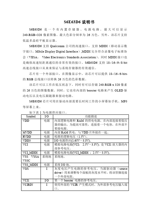
表 5 所示为其他端口。 Symbol I/O 功能描述 DUMMYR[3:1] 电阻测量管脚,正常情况下悬空。 DUMMYL[3:1] DUMMY 无用管脚,悬空即可。 V0/V63 O 伽玛电压镜像管脚。 VDD3DUM O 内部与 VDD3 接在一起。
VSSDUM FUSE_EN RTEST EN_EXCLK EN_CLK TEST_MODE[1:0] TEST_IN[6:0] TE TEST_OUT[2:0]
表 2 系统接口
表3为 Symbol MDP MDN MSP MSN GPIO[9:0] (DB[17:8]) S_CSB(DB [7])
MDDI 管脚作用。 I/O 功能描述 I/O MDDI 数据输入/输出正端,如果 MDDI 不用,该端口悬空。 I/O MDDI 数据输入/输出负端,如果 MDDI 不用,该端口悬空。 I MDDI 数据选通输入正端,如果 MDDI 不用,该端口悬空。 I MDDI 数据选通输入负端,如果 MDDI 不用,该端口悬空。 I/O 总体输入输出,如果在 MDDI 中没有用 GPIO 的话,这些管 脚应该置地。 O 子屏幕驱动 IC 片选信号。 低电平时说明子屏幕驱动 IC 可用,高电平时说明子屏幕驱动
表 1 电源接口
如表 2 所示为系统接口。 Symbol I/O 功能描述 S_PB I 选择 CPU 接口模式,低电平时为并行接口,高电平时为串行 接口。 MDDI_E I 选择 MDDI 接口,低电平时 MDDI 接口不可用,高电平时 N MDDI 接口可用。 ID_MIB I 选择 CPU 种类, 低电平为 intel 80 系列 CPU, 高电平为 motorola 68 系列 CPU,如果 S_PB 是高电平,该端口为 ID 设置端口。 CSB I 片选信号,低电平芯片可用,高电平芯片不可用。 RS I 寄存器选择管脚。 低电平时,指令/状态,高电平时为指令参数/RAM 数据。 不用时需与 VDD3 接在一起。 RW_WR I 管脚作用 CPU 种类 管脚说明 B/SCL RW 68 系列 读写选择,低电平写,高电平读。 WRB 80 系列 写选通作用,在上升沿捕获数据。 SCL 串行接口 时钟同步信号。 E_RDB I 管脚作用 CPU 种类 管脚说明 E 68 系列 读写操作使能端。 RDB 80 系列 读选通作用,低电平时读出数据。 选择串行模式时,将此端口接在 VDD3 上。 SDI I 串行接口的数据输入接口,在 SCL 上升沿捕捉到输入数据,
MEMORY存储芯片MT48LC4M32B2P-6AL中文规格书

V REFDQ CalibrationThe V REFDQ level, which is used by the DRAM DQ input receivers, is internally gener-ated. The DRAM V REFDQ does not have a default value upon power-up and must be set to the desired value, usually via V REFDQ calibration mode. If PDA or PPR modes (hPPR or sPPR) are used prior to V REFDQ calibration, V REFDQ should initially be set at the midpoint between the V DD,max , and the LOW as determined by the driver and ODT termination selected with wide voltage swing on the input levels and setup and hold times of ap-proximately 0.75UI. The memory controller is responsible for V REFDQ calibration to de-termine the best internal V REFDQ level. The V REFDQ calibration is enabled/disabled via MR6[7], MR6[6] selects Range 1 (60% to 92.5% of V DDQ ) or Range 2 (45% to 77.5% of V DDQ ), and an MRS protocol using MR6[5:0] to adjust the V REFDQ level up and down.MR6[6:0] bits can be altered using the MRS command if MR6[7] is disabled. The DRAM controller will likely use a series of writes and reads in conjunction with V REFDQ adjust-ments to obtain the best V REFDQ , which in turn optimizes the data eye.The internal V REFDQ specification parameters are voltage range, step size, V REF step time, V REF full step time, and V REF valid level. The voltage operating range specifies the minimum required V REF setting range for DDR4 SDRAM devices. The minimum range is defined by V REFDQ,min and V REFDQ,max . As noted, a calibration sequence, determined by the DRAM controller, should be performed to adjust V REFDQ and optimize the timing and voltage margin of the DRAM data input receivers. The internal V REFDQ voltage value may not be exactly within the voltage range setting coupled with the V REF set tolerance;the device must be calibrated to the correct internal V REFDQ voltage.Figure 65: V REFDQ Voltage RangeV DDQV REF rangeV SWING smallV SWING large System variance Total rangeV REF ,maxV REF,min4Gb: x4, x8, x16 DDR4 SDRAM V REFDQ CalibrationFigure 92: Self Refresh Exit with NOP Command&.BW&.BF &.(2'7&RPPDQG $''5&6BQ'RQ¶W &DUH 4Gb: x4, x8, x16 DDR4 SDRAM SELF REFRESH Operation。
MB1-10AP 用户手册说明书
User ManualV1.4 M aster Series Embedded SystemIntel ® Apollo Lake ProcessorsEfficient, Versatile, and Rugged & ReliablePREFACECopyright NoticeCopyright © 2016-2020 MiTAC Computing Technology Corporation (MiTAC Group). No part of this document may be reproduced, copied, translated, or transmitted in any form or by any means, electronic or mechanical, for any purpose, without the prior written permission of MiTAC Corp., Ltd. All information and specification provided in this manual are for reference only and remain subject to change without prior notice.DisclaimerWe reserve the right to make changes, without notice, to any product, including circuits and/or software described or contained in this manual in order to improve design and/or performance. We assume no responsibility or liability for the use of the described product(s) conveys no license or title under any patent, copyright, or masks work rights to these products, and make no representations or warranties that these products are free from patent, copyright, or mask work right infringement, unless otherwise specified. Applications that are described in this manual are for illustration purposes only. We make no representation or guarantee that such application will be suitable for the specified use without further testing or modification.Declaration of ConformitySafety InformationSafety PrecautionsFor your safety, please carefully read all the safety instructions before using the device. All cautions and warnings on the equipment should be noted. Keep this user manual for future reference.*Let service personnel to check the equipment in case any of the following problems appear:⏹The power cord or plug is damaged.⏹Liquid has penetrated into the equipment.⏹The equipment has been exposed to moisture.⏹The equipment does not work well or you cannot get it to work according to the user manual.⏹The equipment has been dropped and damaged.⏹The equipment has obvious signs of breakage on the surface.Ordering InformationPacking ListOptional Xpansion Modules MS-01DVI-D10MS-01DPN-D10MS-02COM-D10MS-08DIO-T10CONTENTSPREFACE (2)CHAPTER 1: INTRODUCTION (8)1.1 Overview (8)1.2 Product Features (8)1.3 Hardware Specification (9)1.4 Mechanical Specification (12)1.5 System I/O Placement (13)CHAPTER 2: DIP SWITCH SETTING AND PIN DEFINITION (16)2.1 DIP Switch and Connector Overall Placement (16)2.2 DIP Switch Setting (18)2.3 Connector Pin Definition (19)CHAPTER 3: SYSTEM SETUP (26)3.1 2.5” SATA HDD/SSD Installation (26)3.2 WiFi module Installation (27)3.3 DRAM Installation (28)CHAPTER 4: BIOS SETUP (31)4.1 Main Page (31)4.2 Advance Page (33)4.3 Security Page (42)4.4 Boot Page (46)4.5 Save & Exit Page (47)INTRODUCTIONThis chapter provides the MB1-10AP EmbeddedSystem product overview, including features, hardware and mechanical specifications. 1CHAPTER 1: INTRODUCTIONThis chapter provides the MB1-10AP Embedded System product overview, including features, hardware, mechanical specifications, and I/O placement.1.1 OverviewMiTAC’s MB1-10AP embedded system is the next generation embedded system with Intel® Apollo Lake embedded processor. The efficient performance, OCP/OVP power protection, and expandable design provide the solution for routine tasks and most types of application.1.2 Product FeaturesMB1-10AP Embedded System offers the following features:⏹Intel® Apollo Lake-M N3350/N4200 Processors⏹Support 2 x PoE LAN (Optional)⏹Support HDMI as primary display, and VGA/DisplayPort/DVI-D as second option⏹Fan-less chassis and Expandable module design⏹Support COM/DIO via Xpansion Modules⏹8-24V Wide Power Voltage⏹-25°C to 70°C (For non-PoE SKU, with 0.7m/s Air Flow and Wide TemperatureMemory/Storage)-25°C to 60°C (For PoE SKU, with 0.7m/s Air Flow and Wide TemperatureMemory/Storage)1.3 Hardware Specification*Notes1: Installation in Restricted Access Location (RAL)A restricted access location is a designated area within an incident area (High or Low temperature environment)With authorized people can enter for a period of time and for a specific purpose.1.Access can only be gained by service people or by users who have beeninstructed about the reasons for the Restrictions applied to the location and about any precautions that shall be taken.2.Access is through the use of a tool or lock and key, or other means ofsecurity, and is controlled by the authority Responsible for the location.*Notes2: Please make sure that the power consumption is in the spec of the power supply output capability from AC adaptor (72W or 120W). Please choose the suitable AC adaptor for your application.AC/DC 24V/5A, 120W 3PIN Terminal Block Power Adaptor (For PoE SKU)AC/DC 24V/3A, 72W 3PIN Terminal Block Power Adaptor (For non-PoE SKU)*Note3: Please choose 120W AC adaptor for the Optional Xpansion Module (MS-02COM-D10) COM ports in maximum power loading scenario (12V max. 1A loading).*Note4: Please don’t load the COM power in the hardware configuration and high temperature condition. Don’t operate the machine at maximum operating temperature 70℃(Non-PoE SKU) & 60℃(PoE SKU) with 4*COM 12V*1A loading.*Note 5: The maximum ambient operating temperature is 40°C if the external AC adapter model: EA11011M or EA10681V will be placed in thesame high temperature area with the embedded system.*Note 6: CAUTION - Lithium battery is included in this embedded system. Please do not puncture, mutilate, or dispose of battery in fire. There will be danger of explosion if battery is incorrectly replaced. Replace only with the same or equivalent type recommended by manufacturer. Dispose of used battery according to manufacturer instructions and in accordance with your local regulations.*Note 7: CAUTION - Only allow technically qualified personnel to touch the I/O surface, and only when the unit is well fastened by wall mount, VESA mount, or DIN Rail mount. Please also avoid to contact the I/O surface more than 1 second in high temperature and harsh environment. Not allow to touch aluminum alloy surface at high temperature. The technically qualified personnel also needs to have technical knowledge, operating experiences, and basic knowledge about MB1-10AP product spec.1.4 Mechanical SpecificationMechanical Dimension: 170 mm x 105 mm x 57 mm1.5 System I/O Placement⏹Front I/O:⏹Rear I/O:Xpansion Module (Optional) ConfigurationDIP SWITCH SETTING AND PIN DEFINITIONThis chapter provides information about how to set up thedip switch and use I/Os of MB1-10AP Embedded System hardware. 2CHAPTER 2: DIP SWITCH SETTING AND PIN DEFINITIONThis chapter provides information about how to set up the dip switch, and use internal I/Os of MB1-10AP Embedded System hardware.2.1 DIP Switch and Connector Overall PlacementFront View:Bottom View:2.2 DIP Switch Setting⏹Location #B6ATATX A SW_ATX1CAdd this table in silkscreen TXTDefault ATX mode⏹ Location #B7/B8/B9/B102.3 Connector Pin Definition⏹ Indicator for Realtek RTL8154B LAN⏹ Location #B4 – SATA and SATA PWR Connector3-pin terminal block for DC Input⏹2-pin Remote Power On/Off HeaderMB Side Connector: Molex 151064-0152Suggestive Cable Side Plug: Molex 151100-0002⏹COM1 and COM2 on M/BMB COM1 and COM2 RS232, RS422, RS485 setting is at BIOS setup menuMS-02COM-D10 (Optional)Xpansion Module with 2 x RS232/422/485 (Non-isolation)Support 5V/12V DC Power OutputNotes: Don't support Power HOT switch at SW_PW3 and SW_PW4 in Xpansion Module Below is Xpansion Module with COM3 and COM4: See the power RS232 setting as below table:Default setting is RI signal at A location from SW_RI3 and SW_RI4Power COM setting with RI signal: Default settingSET at A location from SW_RI3 and SW_RI4SET at A location from SW_PW3 and SW_PW4Power 5V setting:SET at C location from SW_RI3 and SW_RI4 SET at A location from SW_PW3 and SW_PW4Power 12V setting:SET at C location from SW_RI3 and SW_RI4 SET at C location from SW_PW3 and SW_PW4Power 12V setting: Change at C location from SW_RI3 and SW_RI4 and at C location from SW_PW3 and SW_PW4MS-08DIO-T10 (Optional)Xpansion Module with 8-bit Optical Isolation DIDO (4 x DI, 4 x DO)SYSTEM SETUPThis chapter provides information about how to set up the MB1-10AP Embedded System hardware installation. 3CHAPTER 3: SYSTEM SETUPThis chapter provides information about how to set up the MB1-10AP Embedded System hardware installation.3.1 2.5” SATA HDD/SSD InstallationPlease follow the instructions to install SATA HDD as below. - Loosen 6 screws from Bottom cover as the arrow locations- Loosen 4 screws as the arrow directions-Move HDD tray as arrow direction-Lift HDD tray about 45 degrees and draw it out-Install 2.5”HDD to the HDD tray3.2 WiFi module Installation-Use mPCIe extension bracket which is in accessories kit to fix half size mPCIe wifi module, and install to the full size mPCIe slot3.3 DRAM Installation-Loosen 4 screws from MB (2 screws from front & rear cover)-Draw the MB sub-assembly out from top cover as arrow direction-Remove the film from top cover & install DIMM to MBBIOS SETUPThis chapter provides information about how to set up BIOS and use BIOS menu items to adjust basic function settings. 4CHAPTER 4: BIOS SETUPThis chapter provides information about how to set up BIOS and use BIOS menu items to adjust basic function settings.4.1 Main Page4.2 Advance Page4.2.1 Intel(R) I210 Gigabit Network Connection4.2.2 Trusted Computing4.2.3 NCT6116D Super IO Configuration4.2.4 Hardware Monitor4.2.5 S5 RTC Wake Setting4.2.6 CPU Configuration4.3 Security Page4.3.1 Secure Boot4.3.2 BIOS Update4.4 Boot Page4.5 Save & Exit Page。
MEMORY存储芯片MT48H16M32L2B5-8中文规格书
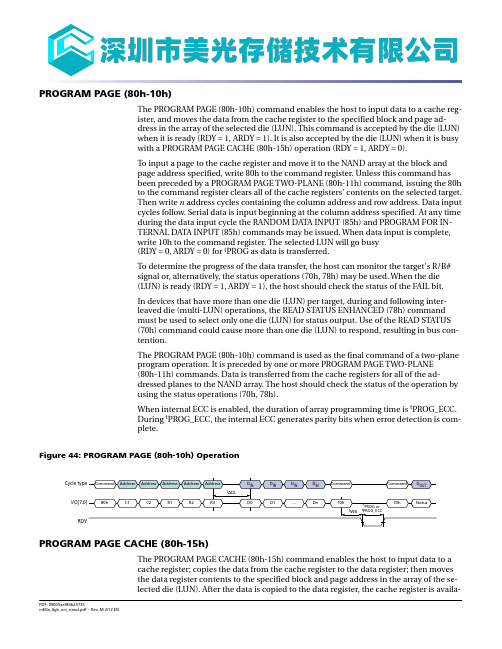
PROGRAM PAGE (80h-10h)The PROGRAM PAGE (80h-10h) command enables the host to input data to a cache reg-ister, and moves the data from the cache register to the specified block and page ad-dress in the array of the selected die (LUN). This command is accepted by the die (LUN)when it is ready (RDY = 1, ARDY = 1). It is also accepted by the die (LUN) when it is busywith a PROGRAM PAGE CACHE (80h-15h) operation (RDY = 1, ARDY = 0).To input a page to the cache register and move it to the NAND array at the block andpage address specified, write 80h to the command register. Unless this command hasbeen preceded by a PROGRAM PAGE TWO-PLANE (80h-11h) command, issuing the 80hto the command register clears all of the cache registers' contents on the selected target.Then write n address cycles containing the column address and row address. Data inputcycles follow. Serial data is input beginning at the column address specified. At any timeduring the data input cycle the RANDOM DATA INPUT (85h) and PROGRAM FOR IN-TERNAL DATA INPUT (85h) commands may be issued. When data input is complete,write 10h to the command register. The selected LUN will go busy(RDY = 0, ARDY = 0) for t PROG as data is transferred.To determine the progress of the data transfer, the host can monitor the target's R/B#signal or, alternatively, the status operations (70h, 78h) may be used. When the die(LUN) is ready (RDY = 1, ARDY = 1), the host should check the status of the FAIL bit.In devices that have more than one die (LUN) per target, during and following inter-leaved die (multi-LUN) operations, the READ STATUS ENHANCED (78h) commandmust be used to select only one die (LUN) for status output. Use of the READ STATUS(70h) command could cause more than one die (LUN) to respond, resulting in bus con-tention.The PROGRAM PAGE (80h-10h) command is used as the final command of a two-planeprogram operation. It is preceded by one or more PROGRAM PAGE TWO-PLANE(80h-11h) commands. Data is transferred from the cache registers for all of the ad-dressed planes to the NAND array. The host should check the status of the operation byusing the status operations (70h, 78h).When internal ECC is enabled, the duration of array programming time is t PROG_ECC.During t PROG_ECC, the internal ECC generates parity bits when error detection is com-plete.Figure 44: PROGRAM PAGE (80h-10h) OperationPROGRAM PAGE CACHE (80h-15h)The PROGRAM PAGE CACHE (80h-15h) command enables the host to input data to acache register; copies the data from the cache register to the data register; then movesthe data register contents to the specified block and page address in the array of the se-lected die (LUN). After the data is copied to the data register, the cache register is availa-READ FOR INTERNAL DATA MOVE (00h-35h)The READ FOR INTERNAL DATA MOVE (00h-35h) command is functionally identical to the READ PAGE (00h-30h) command, except that 35h is written to the command regis-ter instead of 30h.Though it is not required, it is recommended that the host read the data out of the de-vice to verify the data prior to issuing the PROGRAM FOR INTERNAL DATA MOVE (85h-10h) command to prevent the propagation of data errors.If internal ECC is enabled, the data does not need to be toggled out by the host to be corrected and moving data can then be written to a new page without data reloading,which improves system performance.Figure 50: READ FOR INTERNAL DATA MOVE (00h-35h) OperationCycle typeI/O[7:0]RDYFigure 51: READ FOR INTERNAL DATA MOVE (00h–35h) with RANDOM DATA READ (05h–E0h)Cycle type I/O[7:0]RDYI/O[7:0]RDY4Gb, 8Gb, 16Gb: x8, x16 NAND Flash MemoryInternal Data Move OperationsFigure 62: PROGRAM/ERASE Issued to Locked BlockR/B#I/OxtLocked blockREAD STATUSBLOCK LOCK READ STATUS (7Ah)The BLOCK LOCK READ STATUS (7Ah) command is used to determine the protection status of individual blocks. The address cycles have the same format, as shown below,and the invert area bit should be set LOW. On the falling edge of RE# the I/O pins output the block lock status register, which contains the information on the protection status of the block.Table 20: Block Lock Status Register Bit DefinitionsFigure 63: BLOCK LOCK READ STATUSBLOCK LOCK READ STATUSBlock addressCLECE#WE#ALERE#I/Ox4Gb, 8Gb, 16Gb: x8, x16 NAND Flash MemoryBlock Lock FeatureOTP DATA READ (00h-30h)To read data from the OTP area, set the device to OTP operation mode, then issue the PAGE READ (00h-30h) command. Data can be read from OTP pages within the OTP area whether the area is protected or not.To use the PAGE READ command for reading data from the OTP area, issue the 00h command, and then issue five address cycles: for the first two cycles, the column ad-dress; and for the remaining address cycles, select a page in the range of 02h-00h-00h through 1Fh-00h-00h. Lastly, issue the 30h command. The PAGE READ CACHE MODE command is not supported on OTP pages.R/B# goes LOW (t R) while the data is moved from the OTP page to the data register. The READ STATUS (70h) command is the only valid command for reading status in OTP op-eration mode. Bit 5 of the status register reflects the state of R/B# (see Status Opera-tions).Normal READ operation timings apply to OTP read accesses. Additional pages within the OTP area can be selected by repeating the OTP DATA READ command.The PAGE READ command is compatible with the RANDOM DATA OUTPUT (05h-E0h)command.Only data on the current page can be read. Pulsing RE# outputs data sequentially.Figure 68: OTP DATA READWE#CE#ALECLERE#R/B#I/OxNote: 1.The OTP page must be within the 02h–1Fh range.4Gb, 8Gb, 16Gb: x8, x16 NAND Flash Memory One-Time Programmable (OTP) OperationsFigure 77: TWO-PLANE INTERNAL DATA MOVE with RANDOM DATA INPUTR/B#I/Ox4Gb, 8Gb, 16Gb: x8, x16 NAND Flash MemoryTwo-Plane Operations。
MEMORY存储芯片MT28F800B5WG-9BD中文规格书

Table 116: Single-Ended Output Slew RateNotes: 1.SR = slew rate; Q = query output; se = single-ended signals.2.In two cases a maximum slew rate of 12V/ns applies for a single DQ signal within a bytelane:•Case 1 is defined for a single DQ signal within a byte lane that is switching into a cer-tain direction (either from HIGH-to-LOW or LOW-to-HIGH) while all remaining DQ sig-nals in the same byte lane are static (they stay at either HIGH or LOW).•Case 2 is defined for a single DQ signal within a byte lane that is switching into a cer-tain direction (either from HIGH-to-LOW or LOW-to-HIGH) while all remaining DQ sig-nals in the same byte lane are switching into the opposite direction (from LOW-to-HIGH or HIGH-to-LOW, respectively). For the remaining DQ signal switching into theopposite direction, the standard maximum limit of 9 V/ns applies.Differential OutputsTable 117: Differential Output LevelsNote: 1.The swing of ±0.3 × V DDQ is based on approximately 50% of the static single-ended out-put peak-to-peak swing with a driver impedance of R ZQ /7 and an effective test load of 50˖ to V TT = V DDQ at each differential output.Using the same reference load used for timing measurements, output slew rate for fall-ing and rising edges is defined and measured between V OL,diff(AC) and V OH,diff(AC) for dif-ferential signals.Table 118: Differential Output Slew Rate Definition8Gb: x4, x8, x16 DDR4 SDRAM Electrical Characteristics – AC and DC Output Measurement LevelsElectrical Characteristics – Overshoot and Undershoot Specifications Address, Command, and Control Overshoot and Undershoot Specifications Table 111: ADDR, CMD, CNTL Overshoot and Undershoot/SpecificationsFigure 229: ADDR, CMD, CNTL Overshoot and Undershoot DefinitionDD absolute MAX DD absolute MAXSSV o l t s (V )V DD V SS 8Gb: x4, x8, x16 DDR4 SDRAM Electrical Characteristics – Overshoot and Undershoot Specifi-cationsData, Strobe, and Mask Overshoot and Undershoot SpecificationsTable 113: Data, Strobe, and Mask Overshoot and Undershoot/ SpecificationsFigure 231: Data, Strobe, and Mask Overshoot and Undershoot DefinitionDDQ absolute MAX SSQ absolute MIN DDQ absolute MAXSSQ MIN and V o l t s (V )V DDQ V SSQ Electrical Characteristics – AC and DC Output Measurement Levels Single-Ended OutputsTable 114: Single-Ended Output Levels8Gb: x4, x8, x16 DDR4 SDRAM Electrical Characteristics – AC and DC Output Measurement Levels。
- 1、下载文档前请自行甄别文档内容的完整性,平台不提供额外的编辑、内容补充、找答案等附加服务。
- 2、"仅部分预览"的文档,不可在线预览部分如存在完整性等问题,可反馈申请退款(可完整预览的文档不适用该条件!)。
- 3、如文档侵犯您的权益,请联系客服反馈,我们会尽快为您处理(人工客服工作时间:9:00-18:30)。
概述
该产品为电池供电的玩具、低压或者电池供电的运动控制应用提供了一种集成的有刷直流马达驱动解决方案。
电路内部集成了采用N沟和P沟功率MOSFET设计的H桥驱动电路,适合于驱动有刷直流马达或者驱动步进马达的一个绕组。
该电路具备较宽的工作电压范围(从2V到9.6V),最大持续输出电流达到2A,最大峰值输出电流达到 3.5A。
该驱动电路内置过热保护电路。
通过驱动电路的负载电流远大于电路的最大持续电流时,受封装散热能力限制,电路内部芯片的结温将会迅速升高,一旦超过设定值(典型值150℃),内部电路将立即关断输出功率管,切断负载电流,避免温度持续升高造成塑料封装冒烟、起火等安全隐患。
内置的温度迟滞电路,确保电路恢复到安全温度后,才允许重新对电路进行控制。
该驱动电路内置限流保护电路。
当流过功率管的电流超过设定值时,内部电路限流保护电路启动,功率管最大输出电流将被限制在设定值。
该功能可确保电路输出端口与地短路、输出端口之间短路时,电路不烧毁。
特性
●低待机电流(小于0.1uA);
●低静态工作电流;
●集成的H桥驱动电路;
●内置防共态导通电路;
●低导通内阻的功率MOSFET管;
●内置带迟滞效应的过热保护电路(TSD);
●内置限流保护电路,输出对地短路,输出与输出短路,不烧电路;
●抗静电等级:3KV(HBM)。
典型应用
●2-6节AA/AAA干电池供电的玩具马达驱动;
●2-6节镍-氢/镍-镉充电电池供电的玩具马达驱动;
●1-2节锂电池供电的马达驱动
订购信息
应用说明
1、基本工作模式
a)待机模式
在待机模式下,INA=INB=L。
包括驱动功率管在内的所有内部电路都处于关断状态。
电路消耗极低极低的电流。
此时马达输出端OUTA和OUTB 都为高阻状态。
b)正转模式
正转模式的定义为:INA=H,INB=L,此时马达驱动端OUTA输出高电平,马达驱动端OUTB输出低电平时,马达驱动电流从OUTA流入马达,从OUTB流到地端,此时马达的转动定义为正转模式。
c)反转模式
反转模式的定义为:INA=L,INB=H,此时马达驱动端OUTB输出高电平,马达驱动端OUTA输出低电平时,马达驱动电流从OUTB流入马达,从OUTA流到地端,此时马达的转动定义为反转模式。
d)刹车模式
刹车模式的定义为:INA=H,INB=H,此时马达驱动端OUTA以及OUTB都输出低电平,马达内存储的能量将通过OUTA端NMOS管或者OUTB端NMOS快速释放,马达在短时间内就会停止转动。
注意在刹车模式下电路将消耗静态功耗。
e)PWM模式A
当输入信号INA为PWM信号,INB=0或者INA=0,INB为PWM信号时,马达的转动速度将受PWM信号占空比的控制。
在这个模式下,马达驱动电路是在导通和待机模式之间切换,在待机模式下,所有功率管都处于关断状态,马达内部储存的能量只能通过功率MOSFET的体二极管缓慢释放。
注意:在PWM模式A下,当输入信号从高电平跳变为低电平时,按照逻辑要求H桥的4个功率管必须全部进入关断的状态。
MX620B内部设计了关断延迟电路,当输入信号从高电平跳变到低电平时,H桥的NMOS功率管立即关断,而高边的PMOS管仍然会维持30us的导通时间,在此期间电机电流通路如下所示。
f)PWM模式B
当输入信号INA为PWM信号,INB=1或者INA=1,INB为PWM信号时,马达的转动速度将受到PWM信号占空比的控制。
在这个模式下,马达驱动电路输出在导通和刹车模式之间,在刹车模式下马达存储的能量通过低边的NMOS管快速释放。
2、防共态导通电路
在全桥驱动电路中,将半桥内的高边PMOS功率管和低边NMOS功率管同时导通的状态称为共态导通状态。
共态导通将出现一个电源至地的瞬态大电流,该电流会引起额外的功耗损失,极端情况下会烧毁电路。
通过内置死区时间,可避免共态导通。
典型的死区时间为300ns。
3、过热保护电路
当驱动电路结温超过预设温度(典型值为150℃)时,TSD电路开始工作,此时控制电路强制关断所有输出功率管,驱动电路输出进入高阻状态。
TSD电路中设计了热迟滞,只有当电路的结温下降到预设温度(典型值130℃)时,电路返回正常工作状态。
4、限流保护电路
电路内部的比较电路能够实时检测PMOS功率管的导通压降,当导通压降超过内部设定值时,功率管驱动电路将驱动功率PMOS进入线性恒流模式,其最大输出电流由内部电路限制。
结温为27摄氏度时,最大输出电流限制在8A。
结温为140度时,最大输出电流限制在4A。
当输出与地短路或者输出与输出短路时,内部限流保护电路将保护电路不会立即烧毁。
由于短路时所有的功耗都消耗在电路上,因此电路温度急剧上升,电路将立即进入过热关断保护状态。
虽然,在短路状态下电路不会立即烧毁,但如果芯片长期处于短路状态,内部结温过高,将会对芯片的寿命造成一定影响。
5、驱动电路最大持续功耗
该系列马达驱动电路内部均设计有过热保护电路,因此当驱动电路消耗的功耗过大时,电路将进入热关断模式,热关断状态下马达将无法正常工作。
驱动电路最大持续功耗的计算公式为:
P M=(150℃-T A)/θJA
其中150℃为热关断电路预设温度点,T A为电路工作的环境温度(℃),θJA为电路的结到环境的热阻(单位℃/W)。
注意:驱动电路的最大持续功耗与环境温度、封装形式以及散热设计等因素有关,与电路导通内阻并无直接关系。
6、驱动电路功耗
马达驱动电路内部功率MOSFET的导通内阻是影响驱动电路功耗的主要因素。
驱动电路功耗的计算公式为:P D=I L2*R ON其中I L表示马达驱动电路的输出电流,R ON表示功率MOSFET的导通内阻。
注意:功率MOSFET的导通内阻随着温度的升高而升高,在计算电路的最大持续输出电流以及功耗时必须考虑导通内阻的温度特性。
7、驱动电路最大持续输出电流
根据驱动电路的最大持续功耗以及驱动电路功耗可计算出驱动电路的最大持续输出电流,计算公式为:
其中的R ONT为考虑温度特性后的功率MOSFET导通内阻。
注意:驱动电路的最大持续输出电流与环境温度、封装形式、散热设计以及功率MOSFET的导通内阻等因素有关。
8、马达内阻选择
上述分析表明,马达驱动电路的最大持续功耗有限。
如果马达驱动电路所驱动马达内阻极小,其堵转电流超过马达驱动电路所能承受的最大持续输出电流太多,则很容易导致马达驱动电路进入过热关断状态,玩具车在跑动或者反复前进、后退时将出现抖动的现象。
在马达驱动电路选型时,必须考虑马达的内阻.
特别注意事项
1、电源与地反接
将电路的电源与地线反接,将导致电路损坏,严重时会导致塑料封装冒烟。
可考虑在电路的电源端串联一个功率肖特基二极管至电池的正端,可防止由于电池接反引起的电路损坏。
功率肖特基二极管的最大持续电流能力必须大于马达堵转的持续电流,否则肖特基二极管会因为过热而损坏。
功率肖特基二极管的反向击穿电压必须大于最高电源电压,如果反向击穿电压过小,当电池反接时,会击穿肖特基二极管造成烧毁。
2、功率电源VDD对地去耦电容(C1)
驱动电路要求添加的功率电源VDD对地去耦电容C1(参考应用线路图1)主要有两个作用:1)、吸收马达向电源释放的能量,稳定电源电压,避免电路因为过压而击穿;2)、在马达起动或者快速正转、反转切换的瞬间,马达需要瞬间大电流才能迅速启动。
由于电池的响应速度以及连接引线较长,往往不能立即输出瞬态大电流,此时需要依赖靠近马达驱动电路附近的储能电容释放出瞬态大电流。
根据电容的储能特性,电容容值越大,相同时间内的电压波动越小,因此在高压、大电流的应用条件下建议电容C1取值100uF,建议根据具体的应用选择电容值,但是该电容C1取值至少需要 4.7uF。
3、静电防护
电路的输入/输出端口采用了CMOS器件,对静电放电敏感。
虽然设计有静电防护电路,但在运输、包装、加工、储存过程中应该采取防静电措施,尤其是在加工过程中应重点考虑防静电。
4、输出对地短路、输出端短路
电路内部设计有限流保护电路,可以保护电路在遇到短路等异常状况时不会立即损坏。
但切不可将电路长期工作在短路状态下,会对芯片的寿命造成影响。
5、输出对电源短路
在正常工作时,当电路的低电平输出端与电源发生短路时,电路将会被立即损坏。
6、最大峰值电流
电路内部设计了限流电路,在芯片结温较高时,峰值电流较小,此时可能会引起电机正、反切换不能及时响应的情况,在方案评估阶段需要特别注意。
合理选择电机的最大峰值电流。
封装外形尺寸图。