霍尼韦尔SCT-8无线模块说明书
霍尼韦尔移动数据终端8680i佩戴式迷你移动数据终端说明书
移动数据终端特征&优势符合人体工学设计的可穿戴式设备,提高工作效率8680i可穿戴式迷你移动数据终端旨在为频繁的扫描任务提速,解放双手以完成其他所需工作。
购置和使用成本更低高端型8680i提供了可定制的视距屏幕、Wi-Fi以及用于应用开发的SDK,一台设备即可同时代替扫描器 +移动数据终端,大幅简化工作流程。
根据应用需求定制扫描器模块的配件可实现指环或手套等外观形式;可根据尺寸/重量以及使用率的需求来选用超薄型或扩展型电池;也可根据工作流程需求选用标准型或高级型。
坚固耐用可承受从0.5 m(1.6英尺)滚落2,000次,满足严苛工作环境的要求。
霍尼韦尔互联平台通过工作流程分析管理电池寿命周期,确保不间断的整班次运行;设置和固件升级都非常简单。
8680i佩戴式迷你移动数据终端采用人体工学设计,可将关键工作流程信息一览无遗地提供给工作人员,并通过输入实现一机多用。
该设备无需拿在手上,节省了大量的无谓操作,符合人体工学设计的扫描操作能在高频次工作中显著提升效率。
8680i佩戴式迷你移动数据终端8680i是一款紧凑型高性能佩戴式迷你移动数据终端,能大幅提高业务的 工作流程效率。
高端版8680i可代替传统的扫描器和移动数据终端,简化工作流程,一机多用。
可定制的用户显示屏能显示工作流程指令,而且还可通过界面上的两个按钮来完成菜单导航和选项确认。
该移动数据终端通过Wi-Fi和SDK直接连到网络应用。
一台设备可适用于拣取、包装和分类等多种常见应用,更好的人体工学设计,购置成本更低,非常适合替代当前的可穿戴扫描器加移动数据终端解决方案。
标准型设备是一款轻巧、符合人体工学设计,带蓝牙功能的可穿戴扫描 器,在与其他设备配对后可以实现无线通信并传输电池状态和扫描结果等 数据。
通过配置选项可根据环境要求来定制设备。
产品分为双指环和手套(即将推出)两种类型,可根据使用率、班次长度和尺寸/重量等优先级来选用超薄型或扩展型电池。
蜂巢智能温湿度传感器 SCT 系列数据手册说明书

Datasheet2Humidity and Temperature Wall Mount Transducers,SCT SeriesHoneywell Humidity and Temperature Wall Mount Transducers, SCT Series, are an ideal environmental solution for indoor applications such as building automation and HVAC systems in residential and office buildings. The SCT Series utilizesHoneywell HumidIcon™ humidity/temperature sensors to accurately and reliably sense humidity and temperature in the area to enhance user comfort.The SCT Series offers a variety of options and features. The transducers can be equipped with or without a legible LCDdisplay that shows the ambient temperature along with the relative humidity or dew point. The stylish cover trim is available in either silver or gold.Standard output of humidity and temperature is either 4 mA to 20 mA or 0 V to 10 V . The temperature output signal may also be configured with an NTC 10 kOhm, 20 kOhm or PT1000 sensor.INDUSTRY-STANDARD ACCURACY • STABILITY • RELIABILITYP otential ApplicationsINDUSTRIALClimate monitoring and control for: • Residential and office buildings• Production and manufacturing plants • Storerooms• Equipment cabinets • Testing environmentsFeatures•Enhanced accuracy:- ±4 %RH (10 %RH to 90 %RH at 25 °C),±5 %RH (10 %RH to 90 %RH at 5 °C to 50 °C)- Enables the customer to potentially reduce/eliminatetransmitter recalibration cost and supports and optimizes system accuracy and uptime• Long-term stability:- Humidity: ±0.05 %RH typ. and ±1.2 %RH max. drift overfive years- True temperature-compensated humidity elementenables customers to potentially reduce/eliminate the transmitter recalibration cost with enhanced stability over next best alternatives• Enhanced reliability: The humidity sensor element’s multilayerconstruction provides resistance to most applicationhazards such as dust, dirt, condensation, oils and common environmental chemicals, enhancing reliability• Standard humidity output: 4 mA to 20 mA or 0 V to 10 V • Cost-effective• Choice of cover trim color (silver or gold)• Full 0 %RH to 100 %RH measurement range • Available with or without LCD display3SCT SeriesTable 1. Humidity and Temperature PerformanceTable 2. Electrical SpecificationsTable 3. Environmental SpecificationsTable 4. Mechanical SpecificationsHumidity and Temperature Wall Mount TransducersFor example, SCTHWA43SDS de nes an SCT Series humidity and temperature transducer, wall mount, 4 mA to 20 mA output, 4 %RH humidity accuracy, 0.3 °C temperature accuracy/output type, -5 °C to 55 °C temperature range, LCD display, silver cover trim.Wall Mount T SeriesSCTTable 6. Order Guide for No Humidity (Temperature Only) Accuracy Figure 1. Nomenclature Tree 15 SCT SeriesFigure 2. Mounting Dimensions (For reference only: mm/in])With LCD DisplayWithout LCD Display4Humidity and Temperature Wall Mount Transducers Figure 3. DIP Switch Settings1, 22New setting with SW switch will be active once the unit is powered up..Sensing and Productivity Solutions Honeywell1985 Douglas Drive North Golden Valley, MN 55422 Find out moreHoneywell serves its customers through a worldwide network of sales offices, representatives and distributors. For application assistance, current specifications, pricing or name of thenearest Authorized Distributor, contact your local sales office.To learn more about Honeywell’s sensing and control products, call +1-815-235-6847 or 1-800-537-6945, visit , or e-mail inquiries to *********************32302444-A-EN IL50September 2015© 2015 Honeywell International Inc. All rights reserved.WARRANTY/REMEDYHoneywell warrants goods of its manufacture as being free of defective materials and faulty workmanship. Honeywell’s standard product warranty applies unless agreed to otherwise by Honeywell in writing; please refer to your order acknowledgement or consult your local sales office for specific warranty details. If warranted goods are returned to Honeywell during the period of coverage, Honeywell will repair or replace, at its option, without charge those items it finds defective. The foregoing is buyer’s sole remedy and is in lieu of all other warranties, expressed or implied, including those of merchantability and fitness for a particular purpose. In no event shall Honeywell be liable for consequential, special, or indirect damages.While we provide application assistance personally, through our literature and the Honeywell website, it is up to the customer to determine the suitability of the product in the application.Specifications may change without notice. The information we supply is believed to be accurate and reliable as of this printing. However, we assume no responsibility for its use.ADDITIONAL INFORMATIONThe following associated literature is available at : • Application Note• Installation Instructions。
Honeywell MICRO SWITCH SM Series产品说明书

MICRO SWITCH Premium Subminiature Basic SwitchesSM SeriesDESCRIPTIONThe industry-defining name in snap-action switches,Honeywell MICRO SWITCH premium subminiature switches are designed for repeatability and enhanced product life. The MICRO SWITCH SM Series delivers consistent performance within a range of conditions.The MICRO SWITCH SM Series’ small size and light weight are combined with ample electrical capacity, precision operation, and extended life. Featuring high precision and repeatability, the SM Series offers gold contacts for low-energy switching and gold bifurcated contacts for maximum reliability.Bifurcated contacts provide parallel redundancy within the SM switch.The SM switch is available for power-duty switching up to 11 A (Vac) or 1/4 HP (Vac).DIFFERENTIATION• Very wide temperature range allows for years of reliable performance in the harshest of conditions • MIL-PRF-8805 qualified listings• Operating forces as low as 0,06 N [6 g] and differential travel as low as 0,025 mm [0.001 in] delivers consistent, precise switch characteristicsFEATURES• Industry-leading mechanical life of up to 10,000,000 operations• Selection of actuation, electrical termination, and operating characteristics along with high-temperature construction options• Wide temperature range of -54°C to 204°C [-65°F to 400°F]• MIL-PRF-8805 qualified listings in a lightweight, small package• FAA-PMA approvals for commercial aircraft• Choice of silver or gold-plated, or gold bifurcated contacts to handle a variety of electrical load requirements • UL/CSA, cUL, ENEC, and CE approvalsVALUE TO CUSTOMERS• Industry-leading life cycle rating reduces the need to replace switches over life in an OEM platform – reducing total system cost • Low operating forces • Mil-qualified listings• Life of up to 10,000,000 cyclesPOTENTIAL APPLICATIONS• Precision switch assemblies for commercial aircraft to monitor doors for “closed” and “locked” position • Landing gear monitor• Precision switch assemblies for commercial cockpitapplications for pushbuttons, toggle, or joystick assemblies • Precision switch assemblies in military applications• Assemblies for industrial pressure switches and temperature switches• Power generation fuel level (gas and oil)PORTFOLIOThe SM Series of premium subminiature basic switches are a part of a strong offering of submins including SX Series (premium) and ZM, ZM1, ZD, ZX, and ZW Series (standard) switches.Sensing and Internet of Things004959Issue 3Electrical data and UL codes2 * except where stated ±0,38 mm [±0.015 in]Sensing and Internet of Things 34 Sensing and Internet of Things 5Table 5. Numeric Designations for MICRO SWITCH SM Series/Order Guide6 Table 6. SM Series • Standard Actuator Options, Screw Terminals, and Dimensions (mm/in)Pin plunger, T terminalsPin plunger, Solder terminalsIntegral leaf leverIntegral roller leverIntegral leversNOTE: The two mounting holes accept pins or screws of 2,21 mm (0.087 in) maximum diameterMounting torque:0,26 Nm [2.3 in-lb] max.MICRO SWITCH SM SERIES AVAILABLE TERMINALSSensing and Internet of Things 7MICRO SWITCH JS SERIES AUXILIARY ACTUATORS FOR THE MICRO SWITCH SM SERIES SWITCH-ES (stainless steel actuator and hardware)** Travel characteristics on tandem actuators vary with actual basic switch characteristics NOTE: Above actuators should be used below 300°F* “A” measurement is from pivot point of lever to the point indicated on drawing DPlated steel machine screwsWarranty/RemedyHoneywell warrants goods of its manufacture as being free of defective materials and faulty workmanship during the appli-cable warranty period. Honeywell’s standard product warranty applies unless agreed to otherwise by Honeywell in writing; please refer to your order acknowledgement or consult your local sales office for specific warranty details. If warrantedgoods are returned to Honeywell during the period of coverage, Honeywell will repair or replace, at its option, without charge those items that Honeywell, in its sole discretion, finds defec-tive. The foregoing is buyer’s sole remedy and is in lieu of all other warranties, expressed or implied, including those of merchantability and fitness for a particular purpose. In no event shall Honeywell be liable for consequential, special, or indirect damages.While Honeywell may provide application assistance personally, through our literature and the Honeywell web site, it is buyer’s sole responsibility to determine the suitability of the product in the application.Specifications may change without notice. The information we supply is believed to be accurate and reliable as of this writing. However, Honeywell assumes no responsibility for its use.004959-3-EN IL50 GLO December 2016© 2016 Honeywell International Inc. All rights reserved.m WARNINGPERSONAL INJURYDO NOT USE these products as safety or emergency stop devices or in any other application where failure of the product could result in personal injury.Failure to comply with these instructions could result in death or serious injury.m WARNINGMISUSE OF DOCUMENTATION• The information presented in this product sheet is for reference only. Do not use this document as a product installation guide.•Complete installation, operation, and maintenanceinformation is provided in the instructions supplied with each product.Failure to comply with these instructions could result in death or serious injury.Find out moreHoneywell serves its customers through a worldwide network of sales offices and distributors. For application assistance, cur-rent specifications, pricing or name of the nearest Authorized Distributor, contact your local sales office.To learn more about Honey-well’s sensing and switching products,call +1-815-235-6847 or 1-800-537-6945,visit , or e-mail inquiries to *********************ADDITIONAL MATERIALSThe following associated literature is available at :• Product installation instructions • Product range guide • Aerospace range guide • Applying basic switches • Low energy switching guide• Product application-specific information – A pplication Note: Central Vacuum System – A pplication Note: Electronic Taping Machine– Application Note: Sensors and Switches in Sanitary Valves – Application Note: Sensors and Switches in Oil Rig Applications– Application Note: Sensors and Switches for Potential Medical ApplicationsHoneywell Sensing and Internet of Things 9680 Old Bailes Road Fort Mill, SC 29707 。
霍尼韦尔 伏卡安全系统 B208 八路输入模块操作指南说明书
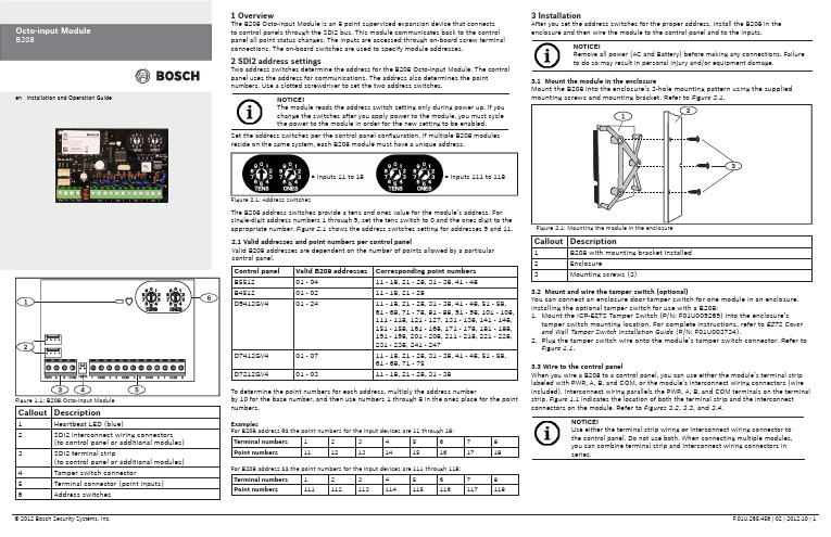
Callout Description1Heartbeat LED (blue)2SDI2 interconnect wiring connectors(to control panel or additional modules) 3SDI2 terminal strip(to control panel or additional modules) 4Tamper switch connector5Terminal connector (point inputs)6Address switches 1 OverviewThe B208 Octo-input Module is an 8 point supervised expansion device that connectsto control panels through the SDI2 bus. This module communicates back to the controlpanel all point status changes. The inputs are accessed through on-board screw terminalconnections. The on-board switches are used to specify module addresses.2 SDI2 address settingsTwo address switches determine the address for the B208 Octo-input Module. The controlpanel uses the address for communications. The address also determines the pointnumbers. Use a slotted screwdriver to set the two address switches.2.1 Valid addresses and point numbers per control panelValid B208 addresses are dependent on the number of points allowed by a particularcontrol panel.3 InstallationAfter you set the address switches for the proper address, install the B208 in theenclosure and then wire the module to the control panel and to the inputs.Control panel Valid B208 addresses Corresponding point numbersB551201 - 0411 - 18, 21 - 28, 31 - 38, 41 - 48B451201 - 0211 - 18, 21 - 28D9412GV401 - 2411 - 18, 21 - 28, 31 - 38, 41 - 48, 51 - 58,61 - 68, 71 - 78, 81 - 88, 91 - 98, 101 - 108,111 - 118, 121 - 127, 131 - 138, 141 - 148,151 - 158, 161 - 168, 171 - 178, 181 - 188,191 - 198, 201 - 208, 211 - 218, 221 - 228,231 - 238, 241 - 247D7412GV401 - 0711 - 18, 21 - 28, 31 - 38, 41 - 48, 51 - 58,61 - 68, 71 - 75D7212GV401 - 0311 - 18, 21 - 28, 31 - 38Figure 2.1: Address switchesTo determine the point numbers for each address, multiply the address numberby 10 for the base number, and then use numbers 1 through 8 in the ones place for the pointnumbers.ExamplesFor B208 address 01the point numbers for the input devices are 11 through 18:Terminal numbers12345678Point numbers1112131415161718For B208 address 11 the point numbers for the input devices are 111 through 118:Terminal numbers12345678Point numbers111112113114115116117118= Inputs 11 to 18= Inputs 111 to 118Set the address switches per the control panel confi guration. If multiple B208 modulesreside on the same system, each B208 module must have a unique address.NOTICE!The module reads the address switch setting only during power up. If youchange the switches after you apply power to the module, you must cyclethe power to the module in order for the new setting to be enabled.The B208 address switches provide a tens and ones value for the module’s address. Forsingle-digit address numbers 1 through 9, set the tens switch to 0 and the ones digit to theappropriate number. Figure 2.1 shows the address switches setting for addresses 9 and 11.3.1 Mount the module in the enclosureMount the B208 into the enclosure’s 3-hole mounting pattern using the suppliedmounting screws and mounting bracket. Refer to Figure 3.1.3.2 Mount and wire the tamper switch (optional)You can connect an enclosure door tamper switch for one module in an enclosure.Installing the optional tamper switch for use with a B208:1. Mount the ICP-EZTS Tamper Switch (P/N: F01U009269) into the enclosure’stamper switch mounting location. For complete instructions, refer to EZTS Coverand Wall Tamper Switch Installation Guide (P/N: F01U003734).2. Plug the tamper switch wire onto the module’s tamper switch connector. Refer toFigure 1.1.3.3 Wire to the control panelWhen you wire a B208 to a control panel, you can use either the module’s terminal striplabeled with PWR, A, B, and COM, or the module’s interconnect wiring connectors (wireincluded). Interconnect wiring parallels the PWR, A, B, and COM terminals on the terminalstrip. Figure 1.1 indicates the location of both the terminal strip and the interconnectconnectors on the module. Refer to Figures 3.2, 3.3, and 3.4.NOTICE!Use either the terminal strip wiring or interconnect wiring connector tothe control panel. Do not use both. When connecting multiple modules,you can combine terminal strip and interconnect wiring connectors inseries.Callout Description1B208 with mounting bracket installed2Enclosure3Mounting screws (3)Figure 1.1: B208 Octo-input Module NOTICE!Remove all power (AC and Battery) before making any connections. Failure to do so may result in personal injury and/or equipment damage.Callout Description1B208 Octo-input Module 2B208 sensor loops31 k Ω EOL resistor (ICP-1K22AWG-10)4Wiring to additional sensor loops3.4 Sensor Loop WiringWire resistance on each sensor loop must be less than 100 Ω with the detection devices connected. The terminal strip supports 12 to 22 AWG (0.65 to 2 mm) wires.The B208 detects open, short, normal, and ground fault circuit conditions on its sensor loops and transmits the conditions to the control panel. Each sensor loop is assigned a point number and transmits to the control panel individually. Run wires away from the premises telephone and AC wiring. Refer to Figure 3.5.4 LED descriptionsThe B208 Octo-input Module includes one blue heartbeat LED to indicate that the module has power and to indicate the module’s current state. Refer(GV4 Series control panel shown)Callout Description1Bosch control panel 2B208 Octo-input ModulesCallout Description1Bosch control panel 2B208 Octo-input Modules(GV4 Series control panel shown)(GV4 Series control panel shown)Callout Description1Terminal strip wiring (SDI2)2Interconnect cable (P/N: F01U079745) (included)Dimensions 2.5 in x 3.8 in x 0.60 in (63.75 mm x 96 mm x 15.25 mm)Voltage (operating)12 V nominal Current (maximum)35 mAOperating temperature +32°F to +122°F (0°C to +50°C)Relative humidity 5% to 93% at +90°F (+32°C) non-condensingLoop inputsUp to eight inputs. Input contacts may be Normally Open (NO) orNormally Closed (NC) with 1k Ω EOL resistor(s) for supervision. NOTICE: Normally Closed (NC) is not permitted in Fire installations.Loop End-of-Line (EOL) resistance1k ΩLoop wiring resistance 100 Ω maximum Loop statesShort: 0 - 1.1 VDCNormal: 1.25 - 1.9 VDC Open: 2.25 - 5 VDCTerminal wire size 12 AWG to 22 AWG (2 mm to 0.65 mm)SDI2 wiringMaximum distance - Wire size (Unshielded wire only): 1000 ft (305 m) - 22 AWG (0.65 mm)1000 ft (305 m) - 18 AWG (2 mm)CompatibilityB5512 (Up to 4 modules)B4512 (Up to 2 modules)D9412GV4 (Up to 24 modules)D7412GV4 (Up to 7 modules)D7212GV4 (Up to 3 modules)7 Speci fi cationsCopyrightThis document is the intellectual property of Bosch Security Systems, Inc. and is protected by copyright. All rights reserved.TrademarksAll hardware and software product names used in this document are likely to be registered trademarks and must be treated accordingly.Determine Bosch Security Systems, Inc. product manufacturing datesUse the serial number located on the product label and refer to the Bosch Security Systems, Inc. web site at /datecodes/.RegionUSUL 365 - Police Station Connected Burglar Alarm Units and Systems UL 609 - Local Burglar Alarm Units and Systems UL 985 - Household Fire Warning System Units UL 1076 - Proprietary Burglar Alarm Units and Systems UL 1023 - Household Burglar-Alarm System Units UL 1610 - Central-Station Burglar-Alarm UnitsUL 864 - Control Units and Accessories for Fire Alarm Systems CSFM - California Of fi ce of The State Fire Marshal FCC Part 15 Class B FM Approval 3010CanadaCAN/ULC-S304 Central and Monitoring Station Burglar Alarm Units ULC/ORD-C1023 Household Burglar Alarm System Units CAN/ULC-S303 Local Burglar Alarm Units and Systems ULC/ORD-C1076 Proprietary Burglar Alarm Units and Systems6 Certi fi cationsFlashing patterns do not start until the tamper is open (short is removed). The following is an example: The version 1.4.3 would be shown as LED fl ashes:[3 second pause] *___****___*** [3 second pause, then normal operation].When the tamper switch is activated (closed to open), the heartbeat LED stays OFF for 3 sec before indicating the fi rmware version. The LED pulses the major, minor, and micro digits of the fi rmware version, with a 1 sec pause after each digit.5 Show the fi rmware versionTo show the fi rmware version using an LED fl ash pattern: - If the optional tamper switch is installed:With the enclosure door open, activate the tamper switch (push and release the switch).- If the optional tamper switch is NOT installed: Momentarily short the tamper pins.。
STD800中文产品说明书(VER.4)

同类最佳的特性: ● 校验量程的精确度高达0.0375% ● 每年的稳定性高达0.01%/满量程,保持10年 ● 自动静压和温度补偿 ● 高达400:1的量程比 ● 响应时间快达90ms ● 多种本地显示功能 ● 外部零位、量程和组态功能 ● 电源极性任意连接 ● 完善的自诊断功能 ● 基于ANSI/NFPA 70-202和ANSI/ISA 12.27.0集成双重密
bar、mbar、inH2O、inHG、FTH2O、mmH2O、mmHG 和psi测量单位 ● 2 行16个字符(高4.13mm x 宽1.83mm) ● 平方根输出指示
高级型图形 LCD 显示表头特性 ● 模块化(可现场增加或拆卸) ● 0、90、180和270度位置调整 ● 提供标准和自定义测量单位 ● 可有3种格式的最多8个显示屏,带棒状图的大PV值或带
封设计,可确保最高安全性 ● 世界一流的耐静压能力:31.5MPa/42MPa ● 标准配置完全符合SIL2/3要求。 ● 全模块设计 ● 最长可提供15年保修
量程和范围限制:
型号
量程上限URL 量程下限LRL 最大量程 最小量程
KPa
KPa
KPa
KPa
STD810
2.5
-2.5
2.5
0.025
STD820 STD830 STD870
组态工具
集成的三按钮组态选项 SmartLine变送器适合所有的电气和环境要求,无论选
择哪种显示表头,都可以通过三个外部按钮进行变送器和显 示表头的组态。无论是否选择显示表头,零位和量程的调整 功能均可通过这些按钮来实现。
手持组态工具 SmartLine变送器在操作员和变送器之间采用双向的通
讯和组态功能。这是通过霍尼韦尔的适用于各种现场需求的 多协议通讯器(MCT202)实现的。MCT202能够现场组态DE 和HART变送器,它还可以在本质安全的环境下使用。所有 霍尼韦尔变送器经设计和测试符合所提供的通讯协议,并且 可与任何经过验证的手持组态设备配合使用。
霍尼韦尔Scorcher Pro 车载电子设备说明书

SECTION 3:READING THE VEHICLE INFORMATIONPOWERING UP THE SCORCHER PRO1.Using the provided HDMI/OBDII Cable from Section 1, plug the device into the vehicle’s OBDII Port commonly found within 24”of the steering column under the driver’s side dash.READING THE VEHICLE’S INFORMATION1.At this point, the key should be in the ignition, but in the OFF position until prompted to turn key ON/RUN position.2.From the Main Menu , select Program Vehicle .3.Processing Data : The Scorcher Pro is now reading your vehicle information.4.Updates: Internet Required . Inorder to install the most up-to-date files the Scorcher Pronow requires internet access. You can access these files via twomethods found in Section 4.SECTION 4:METHODS FOR UPDATING THE SCORCHER PROMETHOD #1: UPDATING VIA WIFI INSIDE THE VEHICLE1.Select Continue from the Internet Required screen.2.Select the WiFi network you would like to connect to. Use the middle button to confirm your selection.3. Enter the network pass code using the arrow keys and the middle button to select.4. Confirm the Wifi settings and select Continue.METHOD #2: UPDATING VIA WIFI USING USB POWER1.Plug the Scorcher Pro into a computer or wall charger using the provided Micro USB Cable.2.Select “Program Vehicle” from the main menu .3. “Vehicle Updates” select “Confirm”.4.“Device Updates” select “Continue”.5.“Internet Required” select “Continue”.6.Follow on screen instruction to set up WiFi.7.Follow on screen prompts until the “Up-To-Date” screen.8.Unplug and return to the vehicle .SECTION 1:PARTS & CHECKLISTSCORCHER PROMICRO USB ™ CABLEMICRO USB™ CABLEHDMI/OBD II CABLEQUICK START GUIDEFuse Puller | Voltage Tester | Battery Charger | PliersTOOLS NEEDED:SECTION 2:PRE-INSTALL CHECKLISTINTERNET ACCESSDuring the installation process you will need to connect the Scorcher Pro to the internet.ALLOW TIME FOR INITIAL SETUPMake sure you have at least an hour to complete the initial setup, update, and installation process.This device is not legal for sale or use in California on pollution controlled vehicles.SECTION 5:TUNING THE VEHICLE1.Cloud Check – If your dealer has sent you a custom tune using the cloud select “continue” to download the custom tune. If not select “Skip” and follow prompts. 2.Select your tune from the following menu items:Pre-Loaded Tune FilesPreloaded aFe Power tunes for use on stock vehicles only.Custom TuneCustom Tuning Dealer files, if there are any on the device.Return to StockRestore original factory file to vehicle.3.Highlight the tune you wish to use and select confirm.4. Read and acknowledge the street use notice.5.Depending on your vehicle there may be further parameters you can change under "Additional Tune Option". Select "Change" to view the available options or "Skip" to continue with downloading the tune only. 6.The Tune and any Additional Tune Options will now beinstalled. Follow the on-screen directions to finish the process.MAIN MENU PROGRAM VEHICLEGAUGES / DATA LOG VEHICLE FUNCTIONSVEHICLE INFO DEVICE INFO DEVICE SETTINGSPROGRAM VEHICLE UPDATE REQUIREDU P for updatesEXIT CONTINUEPROGRAM VEHICLESTREET USE NOTICE This device is NOT LEGAL for sale or use in California on any pollution controlled motor vehicles.Press CONTINUE to start programming.EXITCONTINUEPROGRAM VEHICLECLOUD CHECK Press CONTINUE to query Cloud for available custom tunes.SKIPCONTINUEPROGRAM VEHICLECONNECT TO WIFI SSID (NETWORK NAME)aFePASSCODE (SECURITY KEY)XXXXXEXIT CONTINUENOTE: Please make sure that all stock electronics are turned off and disconnect any aftermarket electronics as well.SECTION 6:LOADING CUSTOM TUNESThe Scorcher Pro is capable of having custom tune files sent over the Cloud straight to the device from aFe. If aFe has chosen to email your file, you can load them onto the device using the Device Updater software. 1.From your e-mail, save your Custom Tunes (.cef files) to your computer’s Desktop.2.Open the Updater software and click the Load Custom Tune File button.3.Click Browse and locate your custom tunes on your Desktop. Alternatively, you can also click Locate Custom Tunes .4.Highlight the Tune you wish to load. The tune you selected should move to the Available Tunes section .5.Select the listed tune in the Available Tunes section, then click the >> button to move the selected tune to the On Device section.6.Highlight the tune under the On Device section , then click program. Tunes can only be loaded one at a time. Repeat steps 3-7 for each tune, the device can hold up to ten custom tunes.2.4.3.7.6.NOTE: During the installation the Scorcher Pro will be married to your (One) vehicle. Once married there is an unlock fee to un-marry the device from your vehicle in or-der to install it on another vehicle.NOTE: Make sure the "Updater Software" from Section 4 Has been completed before proceeding with Section 6.NOTE: To edit the name of the file as it appears on your device, you must highlight the file after transferring the file to the On Device section of Updater. Next to Edit Name , change the name of the file here. Select Save , then Program .EXIT CONFIRMVEHICLE LICENSEYour device is not paired.Select CONFIRM to pair your device with this vehicle.SECTION 8: ADJUSTABLE OPTIONS EXPLAINEDDIESEL VEHICLE SPECIFIC OPTIONS Performance/ExtremeThe most aggressive preloaded diesel tune. Good for everyday use, racing, or economy but not recommended for any type of towing. Street/PerformanceThe Street tune has less power than Performance with a moderate gain over stock, safe for light towing, under 5,000 lbs.Towing/TowThis tune should be used when towing any significant load as the shifting is specific for towing.Trans OnlyFor heavy loads, the engine and boost are left stock and only the transmission shift points are tuned.Jake BrakeHelps to increase engine braking while coasting to help lower braking temperatures.Locked at CTKeeps the torque converter locked during deceleration to aid in engine braking.Lock In 1-2-3Locks the torque converter in 1st, 2nd and 3rd gear.Agg. Tow HaulMore aggressive shift schedule keeping the engine in its power band longer.DIESEL & GAS VEHICLE OPTIONS:Axle RatioCorrects shift patterns / speedometer for aftermarket axles /parts. (Not available on all vehicles)Tire SizeSets tire size to correct shift patterns/speedometer. (Not availableon all vehicles)Idle SpeedSets idle speed in RPM.Traction ControlOn/Off setting disables traction control without using theTCS button.WOT ShiftIncrease or Decrease the WOT shift points of each gear individuallyby MPH.Shift Pressure% change in transmission pressure during shifts. (+ equals firmer,- equals softer)GAS VEHICLE SPECIFIC OPTIONS:Tune TypePerformance levels vary by the octane you select. Higher octanewill provide higher performance increase.Towing TuneAdjusts the octane based tunes to focus more on towingover performance.Global SparkAdd or remove timing advance to the entire RPM range.Spark by RPMAdd or remove timing by RPM range. (0-2000) (2000-4000)(4000-8000)WOT FuelAdd or remove fuel at wide open throttle. (WOT)Fuel InjectorsAllows you to adjust for different sized injectors. (Not available onall vehicles)CMCV DeletesUpdates tune to handle the CMCV/IMRC delete plates modification.Fan ControlLowers the temperature at which the fan turns on.Rev Limiter DriveSets rev limit in RPM while in drive.Rev Limiter NeutralSets rev limit in RPM while in neutral.Speed LimitRemove, increase, or decrease the vehicle speed limiter.(AKA Governor)SECTION 9:FREQUENTLY ASKED QUESTIONSQ: When I try to update my tuner, it says “Please connect device” but it’s already plugged in.A: This is an issue with your PC’s driver software.Q: When I connect the tuner to the vehicle, it doesn’t power on.A: Check for blown fuses specific to the OBDII Port/Cigarette Lighter for your vehicle.Q: Does the tuner have to stay plugged in to keep the vehicle tuned?A: No, after tuning the vehicle you can disconnect the programmer and store it.Q: Can I stack/combine the Scorcher Pro with another chip or tuning module?A: All chips/tuning products must be removed prior to tuning with any device.Q: Can the vehicle be tuned while the engine is running?A: We do not recommend tuning the vehicle while the engine is running as this can cause severedamage to the vehicle and the PCM.Q: Should I return to stock before taking my car to the dealer?A: We recommend that you always return your vehicle to stock before returning to the dealershipas this prevents the tuner from becoming locked if the dealer updates the PCM.Q: My device is telling me my car is a Shelby GT500 when I go to program vehicle or My devicesays Demo Mode when I read Device Info.A: Check device settings and look for Demo Mode. If it is on disable it by turning it to off.This will cause the device to stop identifying your vehicle as a Shelby GT500 and will nowoperate as needed.Q: My vehicle is modified and I loaded a preloaded tune. Now it won’t run as expected.A: In most cases a modified vehicle requires a custom tune. There are set ups in the preloadedtune options to adapt to certain cold air intakes, however this is per vehicle and what works forone vehicle may not work on another.Q: Can I tune more than one vehicle with this programmer?A: No,during the installation the Scorcher Pro will be married to your vehicle. Once married there isan unlock fee to un-marry the device from your vehicle in order to install it on another vehicle. SECTION 7:ON–DEVICE DATA LOGGING1. Connect the Scorcher Pro to the OBDII port.2. From the Main Menu, scroll toGauges/Datalog and press thecenter button on the ScorcherPro.3. On initial setup, you will need to select Configuration press thecenter button, and select yourvehicle from a list of data logfiles. In the future, you cancontinue without going throughthe vehicle selection.4. Once you select your vehicle, the default gauges will show up andcan now be monitored.5.The items being monitored can be adjusted by pressing up ordown on the device to highlight and then pressing the centerbutton on the Scorcher Pro to select which reading you’d liketo change. Within this menu, you can change the item you’remonitoring, and the units in which it will be displaying. You canalso change the layout of the gauges within this menu.6.To start or stop data logging, press the center button on theScorcher Pro while monitoring the gauges.7.While monitoring, press right or left on the device to go tothe Gauges/Datalog menu. From this menu, you may startrecording, select a data log file with which to log, change thegauge layout, and reset the min/max values on the monitor.CONFIGURATIONFORD DIESEL 6.4LFORD DIESEL 6.7LFORD DIESEL 6.0L & 7.3LFORD GAS ʻ07 & PRIOR YEARSFORD GAS ʻ08 & NEWERFORD NON-US ʼ11 & PRIOREXIT CONTINUEMAIN MENUPROGRAM VEHICLEGAUGES / DATA LOGVEHICLE FUNCTIONSVEHICLE INFODEVICE INFODEVICE SETTINGSNOTE: Gauges are defaulted tometric units of measurement.NOTE: Adjustable Options vary for each vehicle and arenot available on all vehicles.BATTERY VOLTAGE12.80MIN:12.20MAX:13.10VBOOSTPSI11.00MIN: 0.00MAX: 12.06COOLANTF202.0MIN: 83.0MAX: 206.0RECLearn more about performance chips and programmers we have.。
Honeywell MICRO SWITCH HS Series 蜂巢封闭大型基本开关数据表说明书

Hermetically Sealed Premium Large Basic SwitchesHS SeriesDESCRIPTIONWhen hermetically sealed switches (metal-to-metal and glass-to-metal sealing) are a requirement for demanding applications, Honeywell MICRO SWITCH™ HS Series premium large basic switches fulfill the need. The HS Series design incorporates a MIL-PRF-8805 symbol 5 hermetic seal to comply with hermetic seal requirements. HS Series switches are capable of controlling logic level/low energy applications, as well as power-dutyswitching to solve many applications. With a compact package size, HS Series switches have overall dimensions of 1.96 inch length, 1.18 inch height, and 0.67 inch wide and are suitable for applications where space is limited.In addition to MIL-PRF-8805 qualified HS Series switches, UL and CSA certified HS Series basic switches are available for a wide variety of applications.VALUE TO CUSTOMERS• Hermetic seal protects the switch mechanism from harmful particle (sand/dust), liquid (water), and gas (corrosive gas and atmospheric pressures) environmentsFEATURES• Select HS catalog listings qualified to MIL-PRF-8805 and/or UL, CSA certified• Hermetic sealing to MIL-PRF-8805 symbol 5 requirements • Similar package size as Honeywell MICRO SWITCH™premium large basic switches with 25,4 mm [1.00 in] mounting centers• Mounting holes of switch are outside of hermetically sealed switch chamber• Several different styles of integral actuators and auxiliary actuators• Electrical connection with #6-32 terminal screws or individual #18 AWG wire leads• Temperature range from -54 °C to 121 °C [-65 °F to 250 °F] with select catalog listings to 149 °C [300 °F]POTENTIAL APPLICATIONS• Commercial and military aircraft in high altitude and deep space equipment for engine valve open/closed position and door latch positions• Food processing equipment• Adverse gas or vapor environmentsDIFFERENTIATION• Capable of controlling electrical circuits from logic level/computer based circuits or electrical circuits up to 25 A • HS Series has the common 25,4 mm [1.00 in] mounting centersPORTFOLIOIn addition to the HS Series hermetically sealed switches,Honeywell offers a complete range of sealed switches for aircraft and military systems. The sealed switches include the EN Series , HM Series , HE Series , HR Series , SE Series , and XE Series .Sensing and Productivity Solutions003128Issue 12 HS SERIES SWITCHESThe HS Series hermetically sealed basic switches are designed for side mounting on 25,4 mm [1.00 in] centers. The mounting of the switch is outside the hermetically sealed switch chamber. The external material for the HS Series is stainless steel and thermoset plastic.Electrical terminations for the HS Series switches are individual wire leads or integral #6-32 terminal screws. CIRCUITRY1PDTELECTROMECHANICAL SWITCHES Array Definitions below explain the meaning ofoperating characteristics. Characteristicsshown in tables were chosen as mostsignificant. They are taken at normal roomtemperature and humidity. These may varyas temperature and humidity conditionsdiffer. Sketches show how characteristicsare measured for in-line plunger actuation.Linear dimensions for in-line actuation arefrom top of plunger to a reference line.Differential Travel (D.T.) – Plunger oractuator travel from point where contacts‘‘snap-over’’ to point where they ‘‘snapback.’’Free Position (F.P.) – Position of switchplunger or actuator when no external forceis applied (other than gravity).Full Overtravel Force – Force required toattain full overtravel of actuator.Operating Position (O.P.) – Position ofswitch plunger or actuator at which pointcontacts snap from normal to operatedposition. Note that in the case of flexible oradjustable actuators, the operating positionis measured from the end of the lever orits maximum length. Location of operatingposition measurement shown on mountingdimension drawings.Operating Force (O.F.) – Amount of forceapplied to switch plunger or actuator tocause contact ‘‘snap-over.’’ Note in thecase of adjustable actuators, the forceis measured from the maximum lengthposition of the lever.Overtravel (O.T.) – Plunger or actuatortravel available beyond operating position.Pretravel (P.T.) – Distance or angletraveled in moving plunger or actuator fromfree position to operating position.Release Force (R.F.) – Amount of forcestill applied to switch plunger or actuatorat moment contacts snap from operatedposition to unoperated position.Total Travel (T.T.) – Distance from actuatorfree position to overtravel limit position.Sensing and Productivity Solutions 34 PRODUCT DIMENSIONS Figure 1. 1HS1 mm [in]Figure 2. 1HS3 mm [in]1 Mounting holes will accept pins or screws of Ø 3,53 [0.139] max. diaNOTEØ 9,8 [0.19] x 4,8 [0.19] Wide1 Mounting holes will accept pins or screws of Ø 3,53 [0.139] max. diaNOTESensing and Productivity Solutions 5Figure 3. 1HS41 mm [in]Figure 4. 4HS4-118 mm [in]1 Mounting holes will accept pins or screws of Ø 3,53 [0.139] max diaNOTE1 Mounting holes will accept pins or screws of Ø 3,53 [0.139] max diaNOTEFigure 5. ADH3721R2 Lever mm [in]NOTES1 Screws, nuts, and lockwashers furnished unassembledWarranty/RemedyHoneywell warrants goods of its manufacture as being free of defective materials and faulty workmanship. Honeywell’sstandard product warranty applies unless agreed to otherwise by Honeywell in writing; please refer to your order acknowledgement or consult your local sales office for specific warranty details. If warranted goods are returned to Honeywell during the period of coverage, Honeywell will repair or replace, at its option, without charge those items it finds defective. The foregoing is buyer’s sole remedy and is in lieu of all other warranties, expressed or implied, including those of merchantability and fitness for a particular purpose. In no event shall Honeywell be liable for consequential, special, or indirect damages.While Honeywell may provide application assistance personally, through our literature and the Honeywell web site, it is up to the customer to determine the suitability of the product in the application.Specifications may change without notice. The information we supply is believed to be accurate and reliable as of this printing. However, we assume no responsibility for its use.003128-1-EN IL50 GLO July 2016© 2016 Honeywell International Inc. All rights reserved.m WARNINGPERSONAL INJURYDO NOT USE these products as safety or emergency stop devices or in any other application where failure of the product could result in personal injury.Failure to comply with these instructions could result in death or serious injury.m WARNINGMISUSE OF DOCUMENTATION•The information presented in this product sheet is for reference only. Do not use this document as a product installation guide.•Complete installation, operation, and maintenanceinformation is provided in the instructions supplied with each product.Failure to comply with these instructions could result in death or serious injury.Find out moreHoneywell serves its customers through a worldwide network of sales offices, representatives and distributors. For application assistance, current specifica-tions, pricing or name of the nearest Authorized Distributor, contact your local sales office. To learn more about Honeywell’s sensing and control products, call +1-815-235-6847 or 1-800-537-6945,visit , or e-mail inquiries to *********************ADDITIONAL MATERIALSThe following associated literature is available on the Honeywell web site at :• Product installation instructions • Aerospace range guideHoneywell Sensing and Productivity Solutions 9680 Old Bailes Road Fort Mill, SC 29707 。
STD800中文产品说明书(VER.4)
运输和存放 ℃
-55 至 120
-55 至 120 0 至 100
1 LCD数显表头工作温度-20℃至+70℃。存放温度-30℃至80℃。 2 对于CTFE填充液,额定值为-15至110℃。 3 短时间等同70℃时2小时。 4 MAWP适用于温度范围-40至125℃。当温度范围在-26至-40℃时,静压限制降为21MPa。石墨O型环的使用会使变送器静压值降为25MPa。
STD800智能差压变送器
1
SmartLine
产品说明书
STD800 SmartLine差压变送器
简介
作为SmartLine®产品系列的成员,STD800是一种采用 先进传感器技术的高性能差压变送器。STD800通过将差压 与传感器芯片上的静压和温度补偿相结合,可在大范围内的 静压和温度下提供极高的测量精确度和稳定性。SmartLine 系列还经过了充分测试,符合Experion® PKS标准,可提供 最高水平的兼容性保证和集成能力。SmartLine产品可轻松 满足压力测量应用的最苛刻的要求。
电脑组态 霍尼韦尔的SCT3000组态工具套件提供了一种简易的方
式来组态数字增强(DE)协议变送器,可将个人计算机用作组 态接口。另外还提供了现场设备管理器 (FDM) 软件和FDM 简捷版来管理HART和Fieldbus设备组态。
系统集成
● SmartLine通讯协议均符合最新发布的 HART/DE/Fieldbus 标准。
Foundation Fieldbus 150ms(依赖主机)
HART:可在 0 至 32 秒内调节,增量为 0.1 秒。默认值:0.50 秒 DE:离散值 0、0.16、0.32、0.48 、1、2、4、8、16、32 秒。默认值:0.48 秒
- 1、下载文档前请自行甄别文档内容的完整性,平台不提供额外的编辑、内容补充、找答案等附加服务。
- 2、"仅部分预览"的文档,不可在线预览部分如存在完整性等问题,可反馈申请退款(可完整预览的文档不适用该条件!)。
- 3、如文档侵犯您的权益,请联系客服反馈,我们会尽快为您处理(人工客服工作时间:9:00-18:30)。
系统特点
• 支持 GPRS 无线网络,采用 AES-128Bit 加密,通信更安全。 • 短消息报警提示,用户可及时获取警情报告,支持 2 个手机用户号码。 • 多种报警方式可选(短信和 GPRS)。 • 支持界面参数配置。 • 支持短信布/撤防。 • 支持双中心方案。
3. 安装与操作
正面图与背面图
OFF ON
OFF
OFF
只连接 1 个接警中心,详细配置参考主机用户手册中 2#MCM-23 SUPER 的相关配置。
上电后,从主机配置中获取所有网络通讯参数。 注意:若 MCM-23 SUPER II 安装于 SCT 系列主机,跳帽设置同上,还需在配置软件中将主机类型选择为 SCT 并 设置相关参数。 如图 1 所示,若 MCM-23 SUPER II 安装于 23 系列主机,跳帽设置如下:
Perform the following steps to install MCM-23 SUPER II: 1. See Figure 1 and Figure 2, insert the SIM card and antenna. 2. Wire the MCM-23 SUPER II and the control panel according to the following figure:
下图为 MCM-23 SUPER II 的正面图和背面图: 图 1 正面图
图 2 背面图
注意:若主机有 CLK 接口,则将其与 MCM-23 SUPER II 的 DCK 接线端子接线。
选择安装位置
如图 1 所示,不接 P1 和 P2 跳帽,然后上电,若 CR1 指示灯闪烁,说明进入信号检测模式。根据指示灯状态查看 信号强度。CR2、CR3、CR4 三个指示灯的状态显示信号强度: • 若只有 1 个指示灯亮,信号为“弱”; • 若其中 2 个指示灯亮,信号为“中”; • 若其中 3 个指示灯亮,信号为“强”。 建议将主机安装于信号强的地点。 若 CR1、CR2、CR3、CR4 四个指示灯同时闪烁,表示该模块为非法模块,模块不工作。
指示灯说明
如图 1 所示,正常工作时的指示灯说明如下:
指示灯 CR1 CR2 CR3
状态 常亮 熄灭 常亮 常亮
说明 与主机连接正常 与主机连接异常 与接警中心 1 连接 与接警中心 2 连接
CR5
闪烁 快速闪烁 常亮
正常运行 信号弱 电源指示灯
4. 报告短信与配置
报告短信格式
当有需要通过短信发送的报告产生时,MCM-23 SUPER II 会将报告短信发送给指定手机号码用户。报告短信的事 件内容和说明如下:
Parts MCM-23 SUPER II
Quantity 1
Antenna
1
User Guide
1
Certification
1
Contact your local retailer as soon as possible if anything is missing in your package.
配置
通过配置软件升级和配置 MCM-23 SUPER II。修改配置后请重启模块。
中国 RoHS
根据信息产业部等部委颁布的《电子信息产品污染控制管理办法》及相关标准的要求,本产品的相关信息如下:
产品中有毒有害物质或元素的名称及含量见下表:
部件名称
印刷电路板组件 线缆
螺丝组件
铅(Pb)
O O O
产品中有毒有害物质或元素的名称及含量 有毒有害物质或元素
Jumper Settings
Follow this table to set the jumpers if the MCM-23 SUPER II is installed on SUPER series control panel (see Figure 1).
© 2015 Honeywell International Inc. Document 800-15900 Rev. C
1. Shipping List
Check if the packing contents match the packing list on receiving the products. The packing list is as below:
3. Installation and Operation
Front & Rear View
The following figure shows the front view and rear view of the MCM-23 SUPER II: Figure 1 Front View
Figure 2 Rear View
霍尼韦尔安防,您值得信赖的安防合作伙伴
Honeywell Security
亚太区总部
中国上海市遵义路 100 号虹桥上海城 A 座 35 楼 电话:+86 21-22196888 传真:+86 21-62370740
Honeywell
MCM-23 SUPER II User Guide
Wiring
P1
P2
P3
P4
描述
ON ON ON OFF 同时与接警中心 1 和接警中心 2 连接。
ON OFF ON OFF 只与接警中心 1 连接。
OFF ON ON OFF 只与接警中心 2 连接。
若 MCM-23 SUPER II 安装于 23 系列主机,设置跳帽后,还需在配置软件中选择对应 23 系列主机类型,并设置相 关参数。
Honeywell
MCM-23 SUPER II 用户手册
接线
按照以下步骤安装 MCM-23 SUPER II: 1. 如图 1 和图 2 所示,分别插入 SIM 卡和天线。 2. 按照下图将 MCM-23 SUPER II 和主机相连:
© 2015 Honeywell International Inc. Document 800-15900 Rev. C
汞(Hg) 镉(Cd)
六价铬(Cr(VI))
多溴联苯(PBB)
O
O
O
O
O
O
O
O
O
O
O
O
多溴二苯醚(PBDE)
O O O
O:表示该有毒有害物质在该部件所有均质材料中的含量均在 SJ/T11363-2006 标准规定的限量要求以下。
X:表示该有毒有害物质至少在该部件的某一均质材料中的含量超出 SJ/T11363-2006 标准规定的限量要求。
跳帽设置
如图 1 所示,若 MCM-23 SUPER II 安装于 SUPER 系列主机,跳帽设置如下:
P1
P2
P3
P4
描述
同时与接警中心 1 和 2 连接,详细配置参考主机的用户 ON ON OFF OFF
手册。
ON
OFF OFF OFF 只连接 1 个接警中心,详细配置参考主机用户手册中
1#MCM-23 SUPER 的相关配置。
注意:MCM-23 SUPER II 安装在 23 系列主机时,在接警中心显示对应的设备名称为 MCM-23。
恢复出厂值(仅针对非 SUPER 系列主机):
上电前安装 P4 跳帽,上电后,取下 P4 跳帽。
默认出厂值如下:
• 主机类型:4 • 安装员码:012345 • 工作方式:000000(短信、GPRS 均关闭) • 所有电话号码全为零 • 键盘地址:06,07 • GPRS 心跳时间:30 秒
Note: If the control panel has CLK terminal, wire it with the DCK terminal of MCM-23 SUPER II.
Select the Installation Location
Do not put the jumpers on P1 and P2 (see Figure 1). Power up and the CR1 indicator flashes, indicating that the system is in signal test mode. Check the signal strength according to the status of the indicators. Indicators CR2, CR3 and CR4 show the strength of the signal: • The signal strength is “low” if only one of the indicators is on; • The signal strength is “middle” if two of the indicators are on; • The signal strength is “high” if all the three indicators are on. It is recommended that the signal strength of the installation location should be “high”. If indicators CR1, CR2, CR3 and CR4 flash simultaneously, it means the module is illegal and it cannot work.
Feature
• Support GPRS wireless network that is protected by the AES-128Bit encryption, providing more reliable communication.
• Instant alarm report by messages; support 2 mobile phone numbers per one MCM-23 SUPER II. • Multiple alarm reporting methods (SMS and GPRS). • Support configuration via the configuration software. • Support arm/disarm via text message. • Support dual CMS solution.