霍尼韦尔静压控制器DC1000中文说明书
Honeywell说明书,通讯00B版doc
32
DC1030 系列接线图
Honeywell
您值得信赖的合做伙伴
33
DC1040 系列接线图
Honeywell
您值得信赖的合做伙伴
34
Honeywell
您值得信赖的合做伙伴
35
Honeywell
您值得信赖的合做伙伴
9
操作说明
Honeywell
您值得信赖的合做伙伴
10
5.
输入
Honeywell
您值得信赖的合做伙伴
11
若客户没有指定输入类型,出厂值预设为 “K2” 其他任意电压电流范围,请来电咨询。
Honeywell
您值得信赖的合做伙伴
12
6.
警报作用
备注: Hold-ON 代表的意思是第一次不报警 .
26
Honeywell
您值得信赖的合做伙伴
27
Honeywell
您值得信赖的合做伙伴
28
Honeywell
您值得信赖的合做伙伴
29
Honeywell
您值得信赖的合做伙伴
30
DC1010 系列接线图
Honeywell
您值得信赖的合做伙伴
31
DC1020 系列接线图
Honeywell
您值得信赖的合做伙伴
Honeywell
您值得信赖的合做伙伴
8
◆ 当SET8.3=1(程序运行时,从“PV”开 始 ) , 即 PV热启动,程序自动扣除运行段的时 间,剩余时间会显示在参数“TIMER”上 ◆ 请非专业人员勿修改“LEVEL 4”层参数, ,否则可能造成控制器内部错误。
4.5
PROGRAM
(用于可编程控制器) LEVEL LEVEL(
霍尼韦尔DC1000系列通用调节器简要说明书(中文版)
DC1000系列通用调节器简要说明书(中文版)HONEYWELL 你值得信赖的合作伙伴注意:使用本手册前,请检查量程,输入,输出是否符合您的要求。
1、面板说明DC1010 DC1020 DC1030 DC10401.1 显示说明PV:过程值(process value),四位显示(红色)SV:设定值( Set Point ),四位显示(绿色)1.2 LED指示灯说明OUT1:第一路输出(OUTPUT1),绿色灯OUT2:第二路输出(OUTPUT2),绿色灯AT :自整定,黄色灯PRO :程序运行中,黄色灯AL1 :第一路报警(ALARM1),红色灯AL2 :第二路报警(ALARM2),红色灯AL3 :第三路报警(ALARM3),红色灯MAN :手动控制,黄色灯。
(DC1010无此功能)1.3 按键SET :设定键(写入设定值或切换模式):移位键(移动设定位数):减少键:增加键A/M :自动(Auto)/手动(Manual)切换键HONEYWELL 你值得信赖的合作伙伴122、 自整定功能(AutoTuning )2.1 将AT 设置为“YES ”,启动自整定功能 2.2 自整定完成后,PID 参数将被自动设定 2.3 ATVL=自整定偏移量,由SP 值推导出来 (它在自整定时,可防止振荡超过设定点)2.4 自整定点失败3、 故障信息(注意)当有“*”标记的故障发生时,控制器需要返修。
主控制传感器开路(INP1) A/D 转换器故障 冷端补偿故障子控制传感器开路(INP2) PV 值超过 USPL (INP1) PV 值低于 LSPL (INP1) 子控制输入信号超过上限(INP2) 子控制输入信号低于下限(INP2) 内存(RAM )故障接口故障自整定失败4.操作流程各阶层进出及参数锁定●进入LEVEL2中设定LCK参数HONEYWELL 你值得信赖的合作伙伴3HONEYWELL 你值得信赖的合作伙伴 44.1.1 按移位键( ◄ )改变参数。
霍尼韦尔DC1040中文说明书
DC1010/1020/1030/1040系列数字控制器操作手册在使用本控制器之前,请先确定控制器的输入输出范围和输入输出种类与您的需求是否相符。
1、面板说明DC1010DC1020DC1030DC10401.1七段显示器PV:过程值(process value),红色4位显示。
SV:设定值(setting value),绿色4位显示。
1.2LEDOUT1:第一路输出(Output1),绿色灯OUT2:第二路输出(Output2),绿色灯AT:自整定(AutoTuning),黄色灯PRO:程序运行中(Program),黄色灯AL1:第一路报警(Alarm1),红色灯AL2:第二路报警(Alarm2),红色灯AL3:第三路报警(Alarm3),红色灯MAN:手动,黄色灯*注意:当发生故障(Error)时,MAN灯亮,输出百分比归零。
1.3按键SET:设定键(写入设定值或切换模式):移位键(移动设定位数):减少键:增加键A/M:自动(Auto)/手动(Manual)切换键2、自整定功能(AutoTuning)2.1将AT(在User Leve中)设定为YES,启动自整定功能2.2ATVL:自整定偏移量(AUTO Tuning offset Vaiue)SV减ATVL为自整定设定点,设定ATVL可以避免自整定时,因PV值振荡而超过设定点(Overshoot).3、故障信息注意:当有“*”标记的故障发生时,请与供应商联系。
4、操作流程(1):按“SET”键。
(2):按“SET”键持续5秒(3):当LCK=‘1111’时,按“SET”键和‘5秒。
(4):当LCK=‘0000’时,按“SET”键和‘’键持续5秒。
1.1Level14.1.1)改变参数。
按下移位键,第一位数开始闪烁。
按增加键()对此数值作增加或减少,再按移位键到第二位数,当所有数值设定好后,按SET 键完成数值设定。
4.1.2SET 键也有转换模式的功能,按下SET 键会显示下一种模式。
DC1000系列数字控制器产品说明说明书
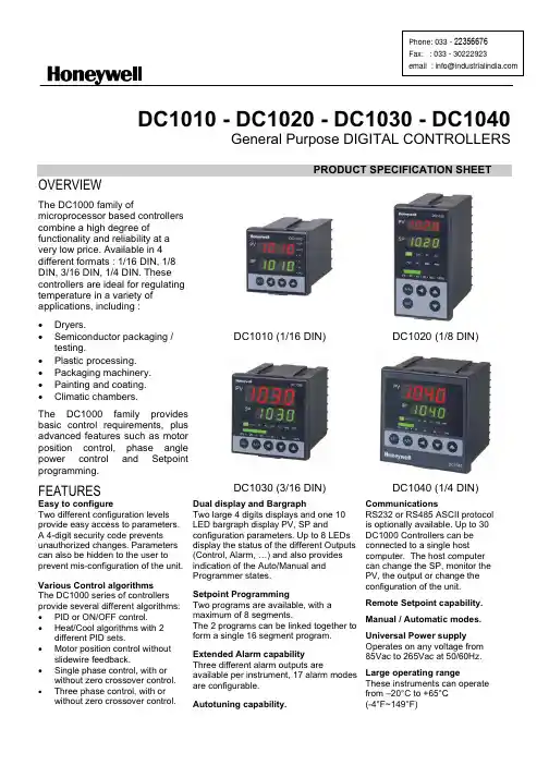
DC1010 - DC1020 - DC1030 - DC1040General Purpose DIGITAL CONTROLLERSPRODUCT SPECIFICATION SHEETDC1010 (1/16 DIN) DC1020 (1/8 DIN)OVERVIEWThe DC1000 family ofmicroprocessor based controllers combine a high degree offunctionality and reliability at a very low price. Available in 4 different formats : 1/16 DIN, 1/8 DIN, 3/16 DIN, 1/4 DIN. These controllers are ideal for regulating temperature in a variety of applications, including : x Dryers.x Semiconductor packaging /testing.x Plastic processing.x Packaging machinery.x Painting and coating.x Climatic chambers.The DC1000 family provides basic control requirements, plus advanced features such as motor position control, phase angle power control and Setpoint programming.FEATURESDC1030 (3/16 DIN)DC1040 (1/4 DIN)Easy to configureTwo different configuration levels provide easy access to parameters. A 4-digit security code prevents unauthorized changes. Parameters can also be hidden to the user to prevent mis-configuration of the unit. Various Control algorithms The DC1000 series of controllers provide several different algorithms: x PID or ON/OFF control.x Heat/Cool algorithms with 2different PID sets.x Motor position control withoutslidewire feedback.x Single phase control, with orwithout zero crossover control. x Three phase control, with orwithout zero crossover control.Dual display and BargraphTwo large 4 digits displays and one 10 LED bargraph display PV, SP andconfiguration parameters. Up to 8 LEDs display the status of the different Outputs (Control, Alarm, …) and also provides indication of the Auto/Manual and Programmer states.Setpoint ProgrammingTwo programs are available, with amaximum of 8 segments. The 2 programs can be linked together to form a single 16 segment program.Extended Alarm capability Three different alarm outputs areavailable per instrument, 17 alarm modes are configurable.CommunicationsRS232 or RS485 ASCII protocol is optionally available. Up to 30 DC1000 Controllers can be connected to a single host computer. The host computer can change the SP, monitor the PV, the output or change the configuration of the unit.Remote Setpoint capability. Manual / Automatic modes. Universal Power supplyOperates on any voltage from85Vac to 265Vac at 50/60Hz. Large operating rangeThese instruments can operate from –20°C to +65°CSPECIFICATIONSThermocouples : K, J, R, S, B, E, N, T, W, PL II, U, L Type of InputRTD : Pt100, JPt100, JPt50PV InputLinear : 4~20mAInput Sampling Time 500 msInput Resolution 14 bit (each)PV/SP Indication 4-digit, 7 segment displayIndicationConstant Value Storage System Non-volatile memory (E2PROM)Indication Accuracy 0.5%FSProportional Band ( P ) 0~200% (On/Off action at P=0)Integral Time ( I ) 0~3600 sec (PD action at I=0)Control ModeDerivative Time ( D ) 0~900 sec (PI action at D=0)Cycle Time 0~150 sec (4~20mA=0, SSR=1, Relay=10)Dead Band Time 0~1000 sec (dead time compensation)Relay Output Electromechanical relayx SPDT contactsx 3A/240VacStatic relay driver output Voltage Pulse, 20VDC/20mAOutputCurrent & Voltage outputs 0~20mA, 4~20mA,0~5V, 0~10V, 1~5V, 2~10VMotor Control Output Servo motor valve control (open loop circuit)Others Phase angle control :9 1M SSR, 3M SSR, 1M SCR, 3M SCRNumber Up to 3 (optional)Modes 17 alarm modes available, hability to ignore the alarmthe first time it occurs :9 Deviation high or low alarms.9 Deviation alarms.9 Band alarm.Alarm9 High or low alarm.9 End of segment alarm.9 Program run indication alarm.9 Timer alarm.Timer One timer is associated with each alarm.Output Signal SP, PVRetransmissionoutput Type of Output 4~20mA, 0~20mA, 0~5V, 0~10V, 1~5V, 2~10VType of Input4~20mA, 0~20mA, 0~5V, 0~10V, 1~5V, 2~10V 2nd Input (Remote SP) Sampling Time 500 ms.Programs Number2 programs of 8 segments each. CommunicationType of CommunicationRS-232 or RS-485. ASCII protocol.Rated Power Supply Voltage & FrequencyAC 85 ~ 265V, 50/60Hz Power Consumption 8VA (110V), 12VA (220V) Ambient Temperature -20°C ~ 65°C (-4°F ~ 149°F) Operating conditionsAmbient Humidity50 ~ 85% RH (non condensing) ApprovalsUL Pending. CE Mark.x PID or ON/OFF control.x Heat/Cool algorithms with 2 different PID sets.x Phase angle controlSingle PhaseThree Phase3I LOADIn phase angle control, power is regulated by changing the point at which the SCR is turned on within each 1/2 period. Single Phase : Output is changed every half-cycle in response to output signals from the Temperature Controller. Three Phase : The outputs are changed every 120° in response to signals from the Temperature Controller. Using this form of control, high-precision temperature control is possible.x Zero-crossover controlSingle Phase1I LOADThree Phase3I LOADThe term Zero-Crossover means that the SCR's are turned on only when the instantaneous value of the sinusoidal wave is zero. Power is then applied for a several continuous half-cycles and then removed for several half-cycles to achieve the desired load power.x Motor position control without slidewire Feedback.MOTOR VALVEMotor position is achieved by using time proportional controlwithout the need for slidewire feedback from the motor shaft. Slidewires wear over a period of time, which can result in poor or intermittent control. This type of control reduces maintenance requirements and removes the need for the controller to be calibrated to the motor feed back potentiometer.DC101050 mm - 1.97 in74.5 mm - 2.97 in13.5 mm 0.53 in6 mm 0.24 in 44 m m - 1.73 i n50 m m - 1.97 i n68 mm - 2.68 in60 m m - 2.36 i n45.5 mm - 1.79 in 45.5 m m - 1.79 i nDC102074.5 mm - 2.97 in13.5 mm 0.53 in6 mm 0.24 in86 mm 3.39 in96 m m - 3.78 i n48 mm - 1.89 in60 mm - 2.36 in91mm 3.58 in45.5mm 1.79 in116 mm 4.57 inDC103074.5 mm - 2.97 in13.5 mm 0.53 in6 mm 0.24 in66 m m - 2.60 i n72 mm - 2.83 in72 m m - 2.83 i n91 mm - 3.58 in69.55 mm 2.74 in91 m m - 3.58 i n69.55 mm 2.74 inContact Details:Industrial Supply Syndicate54, Ezra Street, Kolkata - 700 001, INDIAPhone: 22350923, 22356676 Fax: 91-33-30222923。
DC1000 使用说明书 中文
SV 减 ATVL 为自整定设定点,设定 ATVL 可以避免
自整定时,因 PV 值振荡而超过设定点(Overshoot).
2
上海磊强实业有限公司
3、故障信息
主控制传感器开路(INP1)
*
A/D 转换器故障
*
冷端补偿故障
子控制传感器开路(INP2)
PV 值超过 USPL(INP1)
PV 值低于 LSPL(INP1)
1.3 按键
SET :设定键(写入设定值或切换模式)
:移位键(移动设定位数)
:减少键
:增加键 A/M :自动(Auto)/手动(Manual)切换键
2、 自整定功能(AutoTuning)
2.1 将 AT(在 User Leve 中)设定为 YES,启动自整定功能 2.2 ATVL:自整定偏移量(AUTO Tuning offset Vaiue)
6.2.10 代码 15 : 绝对值高报警不禁止 6.2.11 代码 06 : 绝对值低报警禁止
6.2.12 代码 16 : 绝对值低报警不禁止 6.2.13 代码 07 : 程序段结束报警 (仅用于程序)
14
1)ALD 1~3, 2)AL1~3, 3)ALT1~3,
上海磊强实业有限公司
设定为 07 报警程序段号设定 如果 设定为 0= 报警闪烁
子控制输入信号超过上限(INP2)
子控制输入信号低于下限(INP2)
*
内存(RAM)故障
接口故障
自整定失败
注意:当有“*”标记的故障发生时,请与供应商联系。
4、操作流程
(1):按“SET”键。 (2):按“SET”键持续 5 秒 (3):当 LCK=‘1111’时,按“SET”键和‘ (4):当 LCK=‘0000’时,按“SET”键和‘ 1.1 Level 1
霍尼韦尔DC1000中文说明书

DC1010/1020/1030/1040系列数字控制器操作手册在使用本控制器之前,请先确定控制器的输入输出范围和输入输出种类与您的需求是否相符。
1、面板说明DC1010 DC1020 DC1030 DC10401.1 七段显示器PV:过程值(process value),红色4位显示。
SV:设定值(setting value),绿色4位显示。
1.2 LEDOUT1 :第一路输出(Output1),绿色灯OUT2 :第二路输出(Output2),绿色灯AT :自整定(AutoTuning),黄色灯PRO :程序运行中(Program),黄色灯AL1 :第一路报警(Alarm 1),红色灯AL2 :第二路报警(Alarm 2),红色灯AL3 :第三路报警(Alarm 3),红色灯MAN :手动,黄色灯*注意:当发生故障(Error)时,MAN灯亮,输出百分比归零。
1.3 按键SET :设定键(写入设定值或切换模式):移位键(移动设定位数):减少键:增加键A/M :自动(Auto)/手动(Manual)切换键2、自整定功能(AutoTuning)2.1 将AT(在User Leve中)设定为YES,启动自整定功能2.2 ATVL:自整定偏移量(AUTO Tuning offset Vaiue)SV减ATVL为自整定设定点,设定ATVL可以避免自整定时,因PV值振荡而超过设定点(Overshoot).3、故障信息主控制传感器开路(INP1)* A/D 转换器故障* 冷端补偿故障子控制传感器开路(INP2)PV 值超过 USPL(INP1)PV 值低于 LSPL(INP1)子控制输入信号超过上限(INP2)子控制输入信号低于下限(INP2)* 内存(RAM)故障接口故障自整定失败注意:当有“*”标记的故障发生时,请与供应商联系。
4、操作流程(1):按“SET”键。
(2):按“SET”键持续5秒(3):当LCK=‘1111’时,按“SET”键和‘5秒。
霍尼韦尔DCS操作手册(通用)
霍尼韦尔PKS系统操作手册目录第一章.控制系统介绍 (3)1.Honeywell公司PKS系统概述 (3)2.我公司PKS系统配置 (4)第二章.过程操作 (5)1.画面介绍及操作 (5)1.1.标准画面介绍及操作 (5)1.2.状态行介绍(Unde rstanding the Status Line) (6)1.3.工具栏介绍(Using the Toolbar) (8)1.4.点细目画面及操作 (10)1.5.操作组画面及其操作 (20)1.6.报警功能及其画面操作 (22)1.7.信息摘要及其画面操作 (30)1.8.事件摘要及其画面操作 (32)1.9.警报摘要及其画面操作 (33)1.10.总貌画面 (34)1.11.用户流程图介绍 (34)2.历史数据和趋势操作 (37)2.1.历史数据: (37)2.2.趋势: (38)第一章. 控制系统介绍1.Honeywell公司PKS系统概述DCS系统采用霍尼韦尔的Experion PKS过程知识系统。
Experion PKS 系统是当代最先进的控制系统之一,包含了霍尼韦尔三十年来在过程控制、资产管理、行业知识等方面积累的经验,采用最先进的开放平台和网络技术,为工业企业提供一个统一的、全厂的、自动化过程控制、设备和资产管理、直至生产管理、集成制造等一体化的知识系统体系结构和全系列的解决方案。
Experion PKS系统能满足各种自动化应用要求,为过程控制、SCADA应用和批量控制提供一个开放式控制系统,且满足业界要求的高性能、灵活性、易用性、高可靠性等。
典型Experion PKS系统的体系结构如下图1所示。
图12.我公司PKS系统配置霍尼韦尔提供的系统覆盖范围包括中央控制室、6个现场机柜室,由提供的光纤网络以星形连接方式连接中央控制室和与其关联的各个现场机柜室。
网络图如下图2:图2硬件配置方面,霍尼韦尔公司为神达、昊达公司配置的是PKS系统最新版本R410,其配置如下:l控制器:Experion PKS系统的C300控制器作为DCS主控制器,性能强大,可以与多种IO卡件兼容。
工业测量与控制DC1000系列数字控制器产品手册说明书
Copyright, Notices, and TrademarksPrinted in Taiwan - © Copyright 2004 Honeywell International Inc.Issue 1 - March 2004Warranty / RemedyHoneywell warrants goods of its manufacture as being free to defective materials and faulty workmanship. Contact your local sales office for warranty information. If warranted goods are returned to Honeywell during the period of coverage, Honeywell will repair or replace without charge those items it finds defective. The foregoing is Buyer’s sole remedy and is in lieu of all other warranties, expressed or implied, including those of merchantability and fitness for a particular purpose. Specifications may change without notice. The information we supply is believed to be accurate and reliable as of this printing. However, we assume no responsibility for its use.While we provide application assistance personally, through our literature and the Honeywell web site, it is up to the customer to determine the suitability of the product in the application.© Copyright 2004 Honeywell International Inc.Sales and ServiceHoneywell serves its customers through a worldwide network of sales offices and distributors. For application assistance, current specifications, pricing, or name of the nearest Authorized Distributor, contact your local sales office. See back pageIndustrial Measurement and ControlHoneywell Korea191 HanGangRo 2ga, YongSanGuSeoul, KoreaContents1.Overview (1)1.1Introduction (1)2.Installation (2)2.1Model Number Interpretation (2)2.2Specification (3)2.3Mounting (4)2.4External Dimension (4)2.4.1DC1010 (4)2.4.2DC1020 (5)2.4.3DC1030 (5)2.4.4DC1040 (5)2.5Wiring Diagrams (6)2.5.1DC1010 (7)2.5.2DC1020 (8)2.5.3DC1030 (9)2.5.4DC1040 (10)3.Configuration (11)3.1Operator Interface (11)3.2MODE Access (12)3.3MODEs (13)3.3.1Operation (13)3.3.2Configuration 1 (14)3.3.3Configuration 2 (15)3.4Alarms (17)3.4.1Deviation Alarm (17)3.4.2Absolute Value Alarm (18)3.4.3Program Alarm (19)3.4.4System Alarm (19)3.5Function Lock (20)4.Input Codes (21)4.1Thermocouples (21)4.2RTDs (22)4.3Linear Inputs (22)5.Operation (23)5.1Type of Control (23)5.1.1Manual Operation (23)5.1.2ON/OFF Control (23)5.1.3PID Control (23)5.2Set Point (23)5.3Alarm Set Point (23)6.Error Message (24)1. Overview1.1 IntroductionFunction The DC1000 family of microprocessor based controllers combine ahigh degree of functionality and reliability in 4 different formats: 1/16DIN, 1/8 DIN, 3/16 DIN, and 1/4 DIN.With a typical accuracy of ± 0.5% of span, the DC1000 is an idealcontroller for regulating temperature and other process variables in avariety of applications including dryers, semiconductor packaging &testing, plastic processing, packaging machinery, painting & coating,and climatic chambers.Easy to Configure Two different configuration levels provide easy access to parameters.A 4-digit security code prevents unauthorized changes. Parameterscan also be hidden to the user to prevent improper configuration ofthe unit.Various Control Algorithms The DC1000 series of controllers provides several differentalgorithms:PID or ON/OFF ControlHear/Cool Algorithms with 2 different PID setsMotor Position Control without slidewire feedbackSingle Phase Control with/without zero crossover controlThree Phase Control with/without zero crossover controlMount Anywhere The DC1000 family is industrial control equipments that must bepanel mounted. The wiring terminals must be enclosed within thepanel. The DC1000 is environmentally hardened and, when suitablyenclosed, can be mounted virtually anywhere in plant or factory; onthe wall, in a panel, or even on the process machine. It withstandsambient temperature up to 50°C (122°F).CE Conformity (Europe) This product is in conformity with the protection requirements of thefollowing European Council Directive: 73/23/EEC, the Low VoltageDirective, and 89/336/EEC, the EMC Directive. Conformity of thisproduct with any other “CE Mark” Directive(s) is not guaranteed.Enclosure Rating: Panel-mounted equipment rating IP00. Thiscontroller must be panel mounted and all terminals must be enclosedwithin the panel. Front panel IP65 (IEC 529) option is available.2.4.1 DC10102.4.2 DC10202.4.3 DC10302.4.4 DC1040Upper Limit Deviation Alarm (Alarm Code 11, No alarm release in the first alarming situation)Lower Limit Deviation Alarm (Alarm Code 12, No alarm release in the first alarming situation) Dev. Band Breakaway Alarm(Alarm Code 03, Alarm release in the first alarming situation)Dev. Band Breakaway Alarm(Alarm Code 13, No alarm release in the first alarming situation) Deviation Band Alarm (Alarm Code 04, Alarm release in the first alarming situation) Deviation Band Alarm (Alarm Code 14, No alarm release in the first alarming situation)Absolute Upper Limit Alarm (Alarm Code 15, No alarm release in the first alarming situation)3.4.2.3 Absolute Lower Limit Alarm (Alarm Code 06, Alarm release in the first alarming situation)3.4.2.4 Absolute Lower Limit Alarm (Alarm Code 16, No alarm release in the first alarming situation)Alarm3.4.3 Program3.4.3.1 Segment End Alarm (Alarm Code 07)Once the selected segment is completed, the alarm becomes actuated- ALD1 – ALD3 Set the Alarm Code 07- AL1 – AL3 Enter Segment No. for alarms- ALT1 – ALT3 Define the alarm timing(0 Flickering, 99.59 Continuant, Others Time Delay)3.4.3.2 Program RUN Alarm (Alarm Code 17)While a program runs, the alarm becomes actuatedAlarm3.4.4 System3.4.4.1 System Error Alarm (Alarm Code 08)3.4.4.2 System Error Alarm (Alarm Code 18)3.4.4.3 Timer Alarm (Alarm Code 19)Once the PV reaches to the SP, the alarm becomes actuated after a certain time delay.(Range: 00 hour 00 min – 99 hour 59 min)5. Operation5.1 Type of ControlOperation5.1.1 ManualThe control output can be managed manually. When the ‘A/M’ key is pressed, the parameter of ‘OUTL’ will appear in the upper display, and a fixed control output is shown in lower display (% value). Once the value is changed, the control output is changed and fixed again.Control5.1.2 ON/OFFThe output type must be Relay Output (DC10X0XX-1XX-XXX-X). The ‘P’ value can be changed to 0 in ‘Configuration 1’ mode to produce an ON/OFF control output.When the PV (process variable) reaches the SP (set point), the control output is ON (100%), when it reaches the SP the control output becomes OFF (0%).* To prevent the control output from flickering too frequently the hysteresis (‘HYS1’ in ‘Operation’ mode) is to be set.Control5.1.3 PIDPID control is the default control type of this controller. If ‘AT’ in ‘Operation’ mode becomes ‘YES’, the auto tuning process will start. After the auto tuning is completed, the controller gets optimum PID values for the control system and starts the operation automatically. (PID values can be set manually in ‘Configuration 1’ mode without auto tuning procedure.)Point5.2 SetAfter all the wiring connection is completed and power is applied, the targeted SP (Set Point) is to be entered. When power is applied, the default display is the PV & SP display. The SP may now be entered. (Change the value targeted, and press ‘SET’ key for saving)SetPoint5.3 AlarmIf necessary, each alarm should be set properly.- Set the Alarm Code required in ‘ALd1’ (ALd2 / ALd3) in ‘Configuration 2’ mode(Alarm Code: 00 to 19)- Define the alarm timing required for ‘ALt1’ (ALt2 / ALt3) in ‘Configuration 2’ mode‘0000’ flickering alarm, ‘9959’ continuant alarm‘XXXX’ XX min XX sec (Time Delay)- Enter the deviation value or absolute value in ‘AL1’ (AL2 / AL3) in ‘Operation’ modedepending on the Alarm Code selected above.- Set the hysteresis of alarms in ‘HYSA’ in ‘Configuration 2’ mode. (If necessary)DC1010/1020/1030/1040 Product Manual25Sales and ServiceFor application assistance, current specifications, pricing, or name of the nearest Authorized Distributor, contact one of the offices below. Warranty/RemedyHoneywell warrants goods of its manufacture as being free of defective materials and faulty workmanship. Contact your local sales office for warranty information. If warranted goods are returned to Honeywell during the period of coverage, Honeywell will repair or replace without charge those items it finds defective. The foregoing is Buyer’s sole remedy and is in lieu of all other warranties, expressed or implied, including those of merchantability and fitness for a particular purpose. Specifications may change without notice. The information we supply is believed to be accurate and reliable as of printing. However, we assume no responsibility for its use. While we provide application assistance personally, through our literature and the Honeywell website, it is up to the customer to determine the suitability of the product in the application. © Copyright 2004. Honeywell International Inc. All rights reserved.ASIA PACIFICAustraliaHoneywell Limited Phone: +(61) 2-9370-4500 FAX: +(61) 2-9370-4525 BeijingHoneywell (Tianjin) Ltd Phone: +(86-10) 8458-3280 Fax: +(86-10) 8458-3103 ShanghaiHoneywell (Tianjin) Ltd Phone: (86-21) 6237-0237 Fax: (86-21) 6237-0775 Hong Kong S.A.R. Honeywell Ltd.Phone: +(852) 2953-6412 Fax: +(852) 2953-6767 ChengduHoneywell China Inc. Phone: +(86-28) 8678-6348 Fax: +(86-28) 8678-7061 GuangzhouHoneywell China Inc. Phone: +(86-20) 3879-1169 Fax: +(86-20) 3879-1269 ShenzhenHoneywell China Inc. Phone: +(86) 755-2518-1226Fax: +(86) 755-2518-1221 IndonesiaPT Honeywell Indonesia Phone: +(62) 21-535-8833 FAX: +(62) 21-536-71008 IndiaTATA Honeywell Ltd. Phone: +(91) 20 687 0445/0446Fax: +(91) 20 681 2243/ 687 5992JapanHoneywell IncPhone: +(81) 3 5440 1425 Fax: +(81) 3 5440 1368 South KoreaHoneywell Co., Ltd Phone: +(82) 2 799-6146 Fax: +(82) 2 792-9013 MalaysiaHoneywell Engineering Sdn BhdPhone: +(60-3) 7958-4988 Fax: +(60-3) 7958-8922New ZealandHoneywell LimitedPhone: +(64-9) 623-5050Fax: +(64-9) 623-5060PhilippinesHoneywell Systems(Philippines) Inc.Phone: +(63-2) 633-2830Fax: +(63-2) 638-4013SingaporeHoneywell Pte LtdPhone: +(65) 6355-2828Fax: +(65) 6445-3033ThailandHoneywell Systems(Thailand) Ltd.Phone: +(662) 693-3099FAX: +(662) 693-3085Taiwan R.O.C.Honeywell Taiwan Ltd.Phone: +(886-2) 2245-1000FAX: +(886-2) 2245-3242LATIN AMERICAArgentinaHoneywell S.A.I.C.Phone: +(54-11) 4383-3637FAX: +(54-11) 4325-6470BrazilHoneywell do Brasil & CiaPhone: +(55-11) 7266-1900FAX: +(55-11) 7266-1905ChileHoneywell Chile, S.A.Phone: +(56-2) 233-0688FAX: +(56-2) 231-6679Mexic oHoneywell S.A. de C.V.Phone: +(52) 55 5259-1966FAX: +(52) 55 5570-2985Puerto RicoHoneywell Inc.Phone: +(809) 792-7075FAX: +(809) 792-0053TrinidadHoneywell IncPhone: +(868) 624-3964FAX: +(868) 624-3969VenezuelaHoneywell CAPhone: +(58-2) 238-0211FAX: +(58-2) 238-3391NORTH AMERICACanadaHoneywell LTDPhone: 1-800-737-3360FAX: 1-800-565-4130USAHoneywellControl Products,International HeadquartersPhone: 1-800-537-69451-815-235-6847FAX: 1-815-235-6545E-mail:*********************EUROPEAustriaHoneywell AustriaGes.m.b.H.Phone: +43 (1) 727 80 – 0Fax: +43 (1) 727 80 – 8Balkan CountriesPlease contact theHoneywell Italian officeBelgiumHoneywell SA/NVPhone: +32(0)27282776FAX: +32(0)27282329BulgariaHoneywell EOODPhone: +359 29790017& ext /18 /23 /26FAX: +35-929 790024& +359 29713213Czech RepublicHoneywell spol. s.r.o.Phone: +420 242442205FAX: +420 242442131DenmarkHoneywell A/SPhone: +(45) 39 55 55 55FAX: +(45) 39 55 55 58FinlandHoneywell OYPhone: +358 (3) 2727625FAX: +358 (3) 2728600Franc eHoneywell SAPhone: +33 (0)1 60198075FAX: +33 (0)1 60198201GermanyHoneywell GmbHPhone: +49 (69)8064299FAX: +49 (69)8064931HungaryHoneywell Kft.Phone: +36-1-451 4335FAX: +36-1-451 4343ItalyHoneywell S.p.A.Phone: +39 02 9214 6347FAX: +39 029*******The NetherlandsHoneywell B.V.Phone: +31(0)205656200FAX: +31(0)205656210NorwayHoneywell A/SPhone: +47 66762000FAX: +47 66762090PolandHoneywell Sp. zo.oPhone: +48-22-6060900FAX: +48-22-6060901PortugalHoneywell Portugal S.A.Phone: +351 21 424 5000FAX: +351 21 424 50 99RomaniaHoneywell BucharestPhone: 0040212316437 &0040212316438FAX: 0040212316439Russia and (CIS)Z.A.O. Honeywell, MoscowPhone: +(7 095) 796 98 00/81FAX: +(7 095) 796 98 93/94Slovak RepublicHoneywell s.r.o.Phone: +421-2-58247 400FAX: +421-2-58247 415SpainHoneywell S.A.Phone: +34 (0)91313 61 00FAX: +34 (0)91313 62 78SwedenHoneywell ABPhone: +(46) 8 775 55 00FAX: +(46) 8 775 56 00SwitzerlandHoneywell AGPhone: +41 (1) 855 24 24FAX: +41 (1) 855 24 25TurkeyHoneywell Turkey A.S.Phone: +90 216 575 6600FAX: +90 216 575 6637United KingdomHoneywell Control SystemsL tdPhone: +(44) 1344 655251FAX: +(44) 1344 655554UkraineHoneywellPhone: 38-044 201 4474Fax: 38-044 201 4475AFRICASouth Africa (Republic of)Honeywell Southern AfricaHoneywell S.A. Pty. LtdPhone: +27 11 6958000FAX +27 118051504English Speaking AfricaPlease contact theHoneywell South Africanoffice.French Speaking AfricaPlease contact theHoneywell French office inEUROPEMIDDLE EASTAbu Dhabi U A EMiddle East HeadquartersHoneywell Middle East LtdPhone: +971 24432119FAX: +971 24432536Sultanate of OmanHoneywell & Co Oman LLCPhone: +968 701397FAX +968 787351EgyptHoneywell Egypt LtdPhone: +202 6905516& ext. /17 /18 /19FAX : +202 6905523Saudia ArabiaHoneywell Turki ArabiaLimitedPhone: +966-3-341-0140Fax: +966-3-341-0216KuwaitHoneywell Kuwait KSCPhone: +965 2421327Fax: +965 2428315QatarHoneywell Middle EastPhone: 974-4837768/9Fax: 974-4837765Industrial Measurement & Controls Honeywell Korea191 HanGangRo 2ga YongSanGuSeoul, Korea51-52-25-113 Issue 1 March 2004。
Honeywell DC1000中文说明书
DC1000系列通用调节器简要说明书(中文版)HONEYWELL 你值得信赖的合作伙伴注意:使用本手册前,请检查量程,输入,输出是否符合您的要求。
1、面板说明DC1010 DC1020 DC1030 DC10401.1 显示说明PV:过程值(process value),四位显示(红色)SV:设定值( Set Point ),四位显示(绿色)1.2 LED指示灯说明OUT1:第一路输出(OUTPUT1),绿色灯OUT2:第二路输出(OUTPUT2),绿色灯AT :自整定,黄色灯PRO :程序运行中,黄色灯AL1 :第一路报警(ALARM1),红色灯AL2 :第二路报警(ALARM2),红色灯AL3 :第三路报警(ALARM3),红色灯MAN :手动控制,黄色灯。
(DC1010无此功能)1.3 按键SET :设定键(写入设定值或切换模式):移位键(移动设定位数):减少键:增加键A/M :自动(Auto)/手动(Manual)切换键HONEYWELL 你值得信赖的合作伙伴122、 自整定功能(AutoTuning )2.1 将AT 设置为“YES ”,启动自整定功能 2.2 自整定完成后,PID 参数将被自动设定 2.3 ATVL=自整定偏移量,由SP 值推导出来 (它在自整定时,可防止振荡超过设定点)2.4 自整定点失败3、 故障信息(注意)当有“*”标记的故障发生时,控制器需要返修。
主控制传感器开路(INP1) A/D 转换器故障 冷端补偿故障子控制传感器开路(INP2) PV 值超过 USPL (INP1) PV 值低于 LSPL (INP1) 子控制输入信号超过上限(INP2) 子控制输入信号低于下限(INP2) 内存(RAM )故障接口故障自整定失败4.操作流程各阶层进出及参数锁定●进入LEVEL2中设定LCK参数HONEYWELL 你值得信赖的合作伙伴3HONEYWELL 你值得信赖的合作伙伴 44.1.1 按移位键( ◄ )改变参数。
霍尼韦尔DC1000系列操作手册中文版
1DC1010/1020/1030/1040 产品手册1DC1000系列通用控制器中文操作手册2DC1010/1020/1030/1040 PRODUCT MANUAL3DC1010/1020/1030/1040 产品手册34DC1010/1020/1030/1040 PRODUCT MANUAL5DC1010/1020/1030/1040 产品手册 5LCK=0001, 只进入LEVEL1并允许改变SP 值 LCK=0101, 除改变LCK 功能外,其它任何参数不能改变7DC1010/1020/1030/1040 产品手册79DC1010/1020/1030/1040 产品手册9假设SET8.3=1,SP值西安市将被改成PV值显示。
达到期望SP值的时间将被减少。
达到SP值的剩余时间显示在参数‘TMER’中。
在此,倒计数的时间是与PV值相关,而不是程序段。
11DC1010/1020/1030/1040 产品手册1112DC1010/1020/1030/1040 PRODUCT MANUAL13DC1010/1020/1030/1040 产品手册133) 结束功能如果ALD 设定为 17 (* 参看选择表), 此程序将在程序8或程序段16结束。
* 这样,在显示窗口中的 PV 和 END 将闪烁,报警继电器动作。
如果程序少于八个程序段,控制器就没有END 命令。
这样,请将下一程序段的 OUT 设定为0(out=0),程序就将在下一设定程序段结束。
否则控制器将运行8个或16个程序段。
4) 连接功能PTN=1, 进行模式1, 它包含8个程序段 PTN=2, 进行模式2, 它包含8个程序段PTN=0, 连接进行模式1和模式2 ,共有碍6个程序段 (首先设定PTN1和PTN2, 然后设定 PTN=0)5) 其它功能 (*参看 level 4)SET8.1=1 程序重运行 SET8.2=0 无停电处理功能 SET8.2=1 有停电处理功能(如果电源中断, 控制器仍将保持内存记忆功能。
- 1、下载文档前请自行甄别文档内容的完整性,平台不提供额外的编辑、内容补充、找答案等附加服务。
- 2、"仅部分预览"的文档,不可在线预览部分如存在完整性等问题,可反馈申请退款(可完整预览的文档不适用该条件!)。
- 3、如文档侵犯您的权益,请联系客服反馈,我们会尽快为您处理(人工客服工作时间:9:00-18:30)。
7、接线端子
16
17
子控制 模拟零点设定 子控制 模拟幅度设定 AL1 报警模式
与输入代码 AN1 – AN5 使用相同 范围: LSPL~USPL 与 ANL2 相同
范围: 00~19 参见 P.15 ‘6.1 报警功能选择’
报警 1(AL1)时间设定
用于程序功能 (范围: 0~99.59 min.) 0=闪烁报警, 99.59=连续报警, 其它值 = 延迟时间
: 程序结束报警 (仅用于程序)
AL
6.2.15 代码 08
: 系统失效报警 – 开(ON)
AL
6.2.16 代码 18
: 系统失效报警 – 关(OFF)
6.2.17 代码 09
: 加热中断报警
AL
15
6.2.18 代码 19
: 延迟计时器
AL
当 PV 值 = 报警的 SP 值时, 在报警动作前将延迟一段确定的 时间(即设定时间值)(范围: 00H00M~99H59M)
注意:当有“*”标记的故障发生时,请与供应商联系。
4、操作流程
(1) :按“SET”键。 (2) :按“SET”键持续 5 秒 (3) :当 LCK=‘1111’时,按“SET”键和‘ (4) :当 LCK=‘0000’时,按“SET”键和‘ 1.1 Level 1 ’键持续 5 秒。 ’键持续 5 秒。
4.1.2 4.1.3 4.1.4 4.1.5 SET 键也有转换模式的功能,按下 SET 键会显示下一种模式。 按 SET 键持续 5 秒可进入 LEVEL 2,或同样可返回 LEVEL 1。 如果在一分钟内没有按下任何键,将显示进入 LEVEL 1。 不管处于哪一层,按 A/M 键就可进入 LEVEL 1。
4
4.1.6
输出限幅百分比是“0”时,表示控制器没有输出。
1.2 Level 2
主控制 比例带 主控制 集分时间 主控制 微分时间
主控制 死区时间 主控制 自整定偏移量 主控制 比例循环 主控制 迟滞 子控制 比例带 子控制 集分时间 子控制 微分时间 子控制 比例循环 子控制 迟滞 主控制 间隙 (第一路输出) 子控制 输出间隙(第二路输出) 功能锁定 仅用于 OUTPUT 2, 设定此值 早于 SP 值转为 “OFF” 仅用于第二路输出, 设顶此值早于 SP 值返回“ON” 与 HYS1 相同 与 CYT1 相同 与 D1 相同 与 I1 相同 输出 (SSR � 1, 4~20mA�0, relay�超过 10) 范围: 0~150 秒 * 参考 8.10 循环时间 仅限于 ON/OFF 控制 范围: 0~1000 与 P1 相同
7、报警 7.1 报警选择表(ALD)
代码 / 说明 无报警功能 偏离高限报警 偏离高限报警 偏离低限报警 偏离低限报警 偏离高/低报警 偏离高/低报警 / 偏离高/低范围报警 绝对值高限报警 绝对值高限报警 绝对值低限报警 绝对值低限报警 程序段结束报警 (仅用于程序) 程序段结束报警 (仅用于程序) 系统失效报警 – ON 系统失效报警 – OFF 加热中断报警 - ON (单相) 延时计时器打开报警 Yes No Yes No Yes No No Yes No No Yes 保持(Hold-On)
共有 SET0.1 - SET9.4 可用。
8
PV SP
SET No. (SET 0 . ∗)
SET ∗.1 状态 SET ∗.2 状态 状态定义 0= 锁存 (跳过) 1= 打开 (显示) SET ∗.3 状态 SET ∗.4 状态
5、选型表
9
6、输入 6.1 输入选择表(INP1)
10
11
3
显示 PV 值 显示 SP 值
PV SP
输出限幅 百分点 按 SET 键 持续 5 秒
自整定 状态
第一路报警设定
第二路报警设定
第三路报警设定
4.1.1 按移位键(
)改变参数。按下移位键,第一位数开始闪 )或减少键( )对此数值作增加
烁。按增加键(
或减少,再按移位键到第二位数,当所有数值设定好后, 按 SET 键完成数值设定。
标定输出低值 范围: LSPL~USPL (仅限电流输出) 标定输出高值 范围: 0~9999 (仅限电流输出) 与 CL01 相同
与 CH01 相同
与 CL01 相同
与 CH01 相同
比例马达(无分电器)全开时间 范围: 0~150 秒
程序连续运行 等待时间 继电器接触 & 程序运行 & 报警结束 识别号码 (请跳过次步) 波特率 (请跳过此步) SP 值补偿
范围: C, F, A (模拟)
软过滤 (请跳过此步)
PV 值响应时间调节 (更大,更快) 范围: 0.05~1.00பைடு நூலகம்
7
请跳过此步
动作模式
可选择: 加热, 冷却
控制动作
可选择: PID, Fuzzy(模糊)
频率
可选择: 50, 60Hz
* 检查,如果频率正确。如果不正确,请改正。
1.3 Level 4 (锁存功能) 4.4.1 LCK 功能
: 偏离低限报警不禁止
6.2.6 代码 03
: 高/低限报警禁止
6.2.7 代码 13
: 高/低限报警不禁止
13
6.2.8 代码 04/14 : 高低值范围内报警
6.2.9 代码 05
: 绝对值高报警禁止
6.2.10 代码 15
: 绝对值高报警不禁止
6.2.11 代码 06
: 绝对值低报警禁止
6.2.12 代码 16
DC1010/1020/1030/1040 系列数字控制器 操 作 手 册
1
在使用本控制器之前, 请先确定控制器的输入输出范围和输入输 出种类与您的需求是否相符。
1、 面板说明
DC1010 DC1020 DC1030 DC1040 1.1 七段显示器 PV:过程值(process value),红色 4 位显示。 SV:设定值(setting value),绿色 4 位显示。 1.2 LED OUT1 :第一路输出(Output1),绿色灯 OUT2 :第二路输出(Output2),绿色灯 AT :自整定(AutoTuning),黄色灯 PRO :程序运行中(Program),黄色灯 AL1 :第一路报警(Alarm 1),红色灯 AL2 :第二路报警(Alarm 2),红色灯 AL3 :第三路报警(Alarm 3),红色灯 MAN :手动,黄色灯 *注意:当发生故障(Error)时,MAN 灯亮,输出百分比归零。 1.3 按键 SET :设定键(写入设定值或切换模式) :移位键(移动设定位数) :减少键 :增加键 A/M :自动(Auto)/手动(Manual)切换键
2
3、故障信息
主控制传感器开路(INP1) * * A/D 转换器故障 冷端补偿故障 子控制传感器开路(INP2) PV 值超过 USPL(INP1) PV 值低于 LSPL(INP1) 子控制输入信号超过上限(INP2) 子控制输入信号低于下限(INP2) * 内存(RAM)故障 接口故障 自整定失败
范围: 0~200% 当 P=0 时,ON/OFF 控制 范围: 0~3600 秒 时当 I=0 时,集分关闭 范围: 0~900 秒 当 D=0 时,微分关闭
死区时间补偿 范围: 0~1000 秒 范围: 0~USPL
5
4.3 Level 3 当 LCK=0000, 按 SET 键和 键持续 5 秒,进入 LEVEL 3。
LCK=0100, 进入 Level 1 & 2 并允许改变参数。 LCK=0110, 进入 Level 1 & 2 并允许改变 Level 1 的参数。 LCK=0001, 仅进入 Level 1 并允许改变 SP 值。 LCK=0000, 允许进入 Level 3 然后按 SET + SHIFT 键 ( LCK=1111, 允许进入 Level 4 然后按 SET + SHIFT 键 ( LCK=0101, 除切换 LCK 外,无其它功能。 4.4.2 让显示进入 LEVEL 2 的“LCK”,并设定 LCK=‘1111’ , 然后按 SET+( )键持续 5 秒就进入了“SET“状态。 ) )
主控制 输入选择 主控制 模拟零点设定 Main Control 模拟幅度设定 小数点
选择输入范围 参见 P.13~P.14 5.1 输入选择 与输入代码 AN1 – AN5 使用相同 范围: LSPL~USPL 与 ANL1 相同
设定小数点位置
设定点低限
在 INP1 内设定最低点
设定点高限
在 INP1 内设定最高点
AL2 报警模式
范围: 00~19
报警 2(AL2)时间设定
与 ALT1 相同
AL3 报警模式
范围: 00~19
报警 3(AL3)时间设定
与 ALT1 相同
报警延迟
范围: 0~1000
6
主控制 标定 主控制 高值标定 子控制 低值标定 子控制 高值标定 变送器控制 低值标定 变送器控制 高值标定 计时器控制
: 绝对值低报警不禁止
6.2.13 代码 07
: 程序段结束报警 (仅用于程序)
14
1)ALD 1~3, 2)AL1~3, 3)ALT1~3,
设定为 07 报警程序段号设定 如果 设定为 0= 报警闪烁 设定为 99.59= 报警持续 设定为其它值 = 延迟时间
程序结束 Program End
6.2.14 代码 17
* 注意 : 保持(Hold-On)即指第一次不报警。
1.4 报警动作说明 6.1.1 代码 00/10 : 无报警功能
: SP 值 : 报警设定值
6.1.2 代码 01