光源产品规格书
深圳市天成照明有限公司 TX1812HC 智能外控 LED 光源规格书说明书
◆Description(描述)TX1812HC是一个集控制电路与发光电路于一体的智能外控LED光源。
其外型与一个3838LED灯珠相同,每个元件即为一个像素点。
像素点内部包含了智能数字接口数据锁存信号整形放大驱动电路,电源稳压电路,内置恒流电路,高精度RC振荡器,输出驱动采用专利PWM技术,有效保证了像素点内光的颜色高一致性。
数据协议采用单极性归零码的通讯方式,像素点在上电复位以后,DIN端接受从控制器传输过来的数据,首先送过来的24bit数据被第一个像素点提取后,送到像素点内部的数据锁存器,剩余的数据经过内部整形处理电路整形放大后通过DO端口开始转发输出给下一个级联的像素点,每经过一个像素点的传输,信号减少24bit。
像素点采用自动整形转发技术,使得该像素点的级联个数不受信号传送的限制,仅仅受限信号传输速度要求。
LED具有低电压驱动,环保节能,亮度高,散射角度大,一致性好,超低功率,超长寿命等优点。
将控制电路集成于LED上面,电路变得更加简单,体积小,安装更加简便。
◆Applications(领域)LED全彩发光字灯串,LED全彩模组,LED幻彩软硬灯条,LED护栏管,LED外观/情景照明。
LED点光源,LED像素屏,LED异形屏,各种电子产品,电器设备跑马灯。
◆Features(特征)LED内部集成高质量外控单线串行级联恒流IC。
控制电路与芯片集成在SMD3838元器件中,构成一个完整的外控像素点,色温效果均匀且一致性高。
内置数据整形电路,任何一个像素点收到信号后经过波形整形再输出,保证线路波形畸变不会累加。
内置上电复位和掉电复位电路,上电不亮灯。
灰度调节电路(256级灰度可调)。
默认输出恒流值12mA,便于降低灯珠功耗。
默认上电不亮灯。
数据传输频率可达800Kbps,当刷新速率30帧/秒时,级联数不小于1024点。
◆Package Dimensions(封装尺寸)注;1.所有标注尺寸的单位均为毫米2.除了特别注明,所有标注尺寸的公差均为±0.2mm3.封装尺寸:3.5x3.5x1.3mm◆Product naming principle(产品命名原则)◆Pin figure(引脚图)◆Pin function(引脚图)序号符号管脚名功能描述1GND地信号接地和电源接地2NC空脚PCB上做悬空处理3DIN数据输入控制数据信号输入4VDD电源供电管脚,PCB上两供电管脚可做连通处理5VDD电源供电管脚,PCB上两供电管脚可做连通处理6DO数据输出控制数据信号输出Electro-optical characteristics at Ta=25℃(电光特性)◆Absolute maximum ratings at Ta=25℃(绝对最大额定值)参数符号范围单位逻辑电源电压VDD 3.0~+7.5V R/G/B输出端口电压Lol15mA 工作温度Topt-40-85℃℃储存温度Tstg-40-120℃℃◆Electric Spec(电气参数)参数符号最小典型最大单位测试条件芯片输入电压VDD-- 5.07.5V--OUT输出电流Iout--12--mA--高电平输入电压Vin0.7V DD----V VDD=5.0V 低电平输入电压Vil----0.3V DD V VDD=5.0V PWM频率FPWM--4--KHZ--静态功耗IDD--0.3--mA--◆dynamic parameter (动态参数)参数符号最小典型最大单位测试条件数据速率F DIN --8001100KHZ --传输延迟时间Tpzl--500--nsDIN-DO◆The data transmissiontime (数据传输时间)◆Temporal waveform figure (时序波形图)输入码型:连接方式:码码码◆mode of data transmission(数据传输方式)◆mode of data transmission(数据传输方式)G7G6G5G4G3G2G1G0R7R6R5R4R3R2R1R0B7B6B5B4B3B2B1B0注:高位先发,按照GRB的顺序发送数据(G7→G6 0◆Typical application circuit(典型应用电路)◆Typical optical characteristics curves (典型光学特性曲线)1.21.00.80.60.40.20.0400 450 500 550 600 650 700Wavelength[nm]Spectral DistributionRelative Intensity vs.Wavelength(Ta=25。
台湾葳天UV3535光源规格书
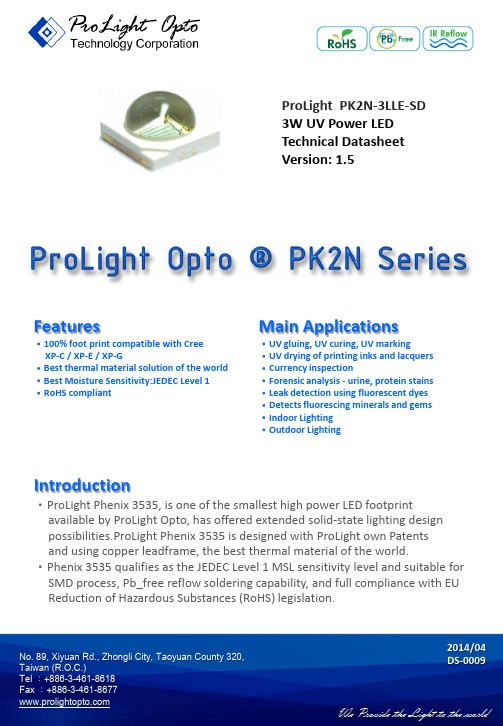
No. 89, Xiyuan Rd., Zhongli City, Taoyuan County 320, ProLight PK2N-3LLE-SD 3W UV Power LED Technical Datasheet Version: 1.5Features‧100% foot print compatible with Cree XP-C / XP-E / XP-G‧Best thermal material solution of the world ‧Best Moisture Sensitivity:JEDEC Level 1 ‧RoHS compliantIntroduction‧ProLight Phenix 3535, is one of the smallest high power LED footprintavailable by ProLight Opto, has offered extended solid-state lighting design possibilities.ProLight Phenix 3535 is designed with ProLight own Patents and using copper leadframe, the best thermal material of the world.‧Phenix 3535 qualifies as the JEDEC Level 1 MSL sensitivity level and suitable for SMD process, Pb_free reflow soldering capability, and full compliance with EU Reduction of Hazardous Substances (RoHS) legislation.2014/04 Main Applications‧UV gluing, UV curing, UV marking‧UV drying of printing inks and lacquers ‧Currency inspection‧Forensic analysis - urine, protein stains ‧Leak detection using fluorescent dyes ‧Detects fluorescing minerals and gems ‧Indoor Lighting ‧Outdoor LightingEmitter Mechanical DimensionsNotes:1. The cathode side of the device is denoted by the chamfer on the part body.2. Electrical insulation between the case and the board is required. Do not electrically connecteither the anode or cathode to the slug.3. Drawing not to scale.4. All dimensions are in millimeters.5. Unless otherwise indicated, tolerances are ± 0.10mm.6. Please do not solder the emitter by manual hand soldering, otherwise it will damage the emitter.7. Please do not use a force of over 0.3kgf impact or pressure on the lens of the LED, otherwiseit will cause a catastrophic failure.*The appearance and specifications of the product may be modified for improvement without notice.2No. 89, Xiyuan Rd., Zhongli City, Taoyuan County 320,No. 89, Xiyuan Rd., Zhongli City, Taoyuan County 320, 3Flux Characteristics, T J = 25°CRadiation Pattern ColorPart Number EmitterRadiometric Power (mW) @350mA Refer @700mAMinimum Typical Minimum TypicalLambertianUVPK2N-3LLE-SD335 510650950●ProLight maintains a tolerance of ± 10% on flux and power measurements.● Please do not drive at rated current more than 1 second without proper heat sink.Thermal Forward Voltage V F (V)Forward Voltage V F (V)Resistance @ 350mARefer @700mAJunction to ColorMin. Typ. Max.Typ.Slug (°C/ W)UV2.853.23.85 3.68●ProLight maintains a tolerance of ± 0.1V for Voltage measurements.Electrical Characteristics, T J = 25°COptical Characteristics at 350mA, T J = 25°CTotal included Viewing Angle Angle Radiation ColorPeak Wavelength λP(degrees) (degrees) PatternMin.Typ.Max.θ0.90V2 θ1/2 LambertianUV390 nm400 nm410 nm160130●ProLight maintains a tolerance of ± 1nm for dominant wavelength measurements.No. 89, Xiyuan Rd., Zhongli City, Taoyuan County 320, Absolute Maximum RatingsParameterUVDC Forward Current (mA)700Peak Pulsed Forward Current (mA) 1000 (less than 1/10 duty cycle@1KHz)Average Forward Current (mA) 700ESD Sensitivity±4000V (Class III)(HBM per MIL-STD-883E Method 3015.7) LED Junction Temperature 120°C Operating Board Temperature -40°C - 90°Cat Maximum DC Forward Current Storage Temperature -40°C - 120°C Soldering Temperature JEDEC 020c 260°CAllowable Reflow Cycles 3Reverse VoltageNot designed to be driven in reverse bias4ColorBin CodeMinimum MaximumAvailable Radiometric Power (mW) Radiometric Power (mW)Color BinsUVP 335 435 【1】Q 435 515 2, 3, 4 【1】R 515 635 2, 3, 4 【1】S 635 755【1】●ProLight maintains a tolerance of ± 10% on flux and power measurements. ● The flux bin of the product may be modified for improvement without notice.● 【1】The rest of color bins are not 100% ready for order currently. Please ask for quote and order possibility.Radiometric Power Bin Structure at 350mANo. 89, Xiyuan Rd., Zhongli City, Taoyuan County 320, ColorBin CodeMinimum Peak Maximum Peak Wavelength (nm)Wavelength (nm)UV1 390 3952 395 4003 400 4054 405 410●ProLight maintains a tolerance of ± 1nm for peak wavelength measurements.Peak Wavelength Bin Structure5Forward Voltage Bin StructureColorBin CodeMinimum Voltage (V)Maximum Voltage (V)UVA 2.85 3.10B 3.10 3.35 D 3.35 3.60 E3.603.85●ProLight maintains a tolerance of ± 0.1V for Voltage measurements.Note: Although several bins are outlined, product availability in a particular bin varies by production run and by product performance. Not all bins are available in all colors.No. 89, Xiyuan Rd., Zhongli City, Taoyuan County 320, 1. UV6Color Spectrum, T J = 25°C0.00.2 0.4 0.6 0.8 1.0 350400 450 500 550 600 650 700 750 800R e l a t i v e S p e c t r a l P o w e r D i s t r i b u t i o nWavelength (nm)Light Output CharacteristicsRelative Light Output vs. Junction Temperature at 700mA0 20 40 60 80 100 120 140 160 020406080100120R e l a t i v e L i g h t O u t p u t (%)Junction Temperature, T J (℃)UVNo. 89, Xiyuan Rd., Zhongli City, Taoyuan County 320, 0 100 200 300 400 500 600 700 800 0255075100125150F o r w a r d C u r r e n t (m A )Ambient Temperature (℃)R θJ-A = 30°C/W R θJ-A = 25°C/W R θJ-A = 15°C/WR θJ-A = 20°C/W 0.00.2 0.4 0.6 0.8 1.0 1.2 1.4 1.6 1.8 2.0 0200400600800R e l a t i v e L u m i n o u s F l u xForward Current (mA) 0100 200 300 400 500 600 700 800 0 0.5 1 1.5 2 2.5 3 3.5 4A v e r a g e F o r w a r d C u r r e n t (m A )Forward Voltage (V)Forward Current Characteristics, T J = 25°CFig 1. Forward Current vs. Forward Voltage for UV.Fig 2. Relative Luminous Flux vs. Forward Current for UV at T J =25 maintained.7Ambient Temperature vs. Maximum Forward Current1. UV (T JMAX = 120°C)No. 89, Xiyuan Rd., Zhongli City, Taoyuan County 320, 8Typical Representative Spatial Radiation PatternLambertian Radiation Pattern0 10 20 30 40 50 60 70 80 90 100 -100-80-60-40 -20 0 20 406080100R e l a t i v e I n t e n s i t y (%)Angular Displacement (Degrees)Soak RequirementsLevel Floor Life Standard Accelerated Environment Time Conditions Time (hours) Conditions Time (hours) Conditions1 Unlimited ≤30°C /168 +5/-085°C /NA NA 85% RH 85% RH●The standard soak time includes a default value of 24 hours for semiconductor manufature'sexposure time (MET) between bake and bag and includes the maximum time allowed out ofthe bag at the distributor's facility.●Table below presents the moisture sensitivity level definitions per IPC/JEDEC's J-STD-020C.Soak Requirements Level Floor Life Standard Accelerated Environment Time Conditions Time (hours) Conditions Time (hours) Conditions1 Unlimited ≤30°C /168 +5/-085°C /NA NA 85% RH 85% RH2 1 year ≤30°C /168 +5/-085°C /NA NA 60% RH 60% RH2a 4 weeks ≤30°C /696 +5/-030°C /120 +1/-060°C / 60% RH 60% RH 60% RH3 168 hours ≤30°C /192 +5/-030°C /40 +1/-060°C / 60% RH 60% RH 60% RH4 72 hours ≤30°C /96 +2/-030°C /20 +0.5/-060°C / 60% RH 60% RH 60% RH5 48 hours ≤30°C /72 +2/-030°C /15 +0.5/-060°C / 60% RH 60% RH 60% RH5a 24 hours ≤30°C /48 +2/-030°C /10 +0.5/-060°C / 60% RH 60% RH 60% RH6 Time on Label ≤30°C / Time on Label 30°C /NA NA (TOL) 60% RH (TOL) 60% RHMoisture Sensitivity Level - JEDEC Level 1No. 89, Xiyuan Rd., Zhongli City, Taoyuan County 320,9No. 89, Xiyuan Rd., Zhongli City, Taoyuan County 320,Stress TestStress ConditionsStress Duration Failure Criteria Room Temperature25°C, I F = max DC (Note 1)1000 hoursNote 2Operating Life (RTOL)Wet High Temperature85°C/60%RH, I F = max DC (Note 1)1000 hoursNote 2Operating Life (WHTOL)Wet High Temperature85°C/85%RH, non-operating1000 hoursNote 2Storage Life (WHTSL)High Temperature110°C, non-operating1000 hoursNote 2Storage Life (HTSL)Low Temperature-40°C, non-operating1000 hoursNote 2Storage Life (LTSL)Non-operating -40°C to 120°C, 30 min. dwell,200 cyclesNote 2Temperature Cycle (TMCL) <5 min. transferNon-operating -40°C to 120°C, 20 min. dwell,200 cyclesNote 2Thermal Shock (TMSK) <20 sec. transferMechanical Shock1500 G, 0.5 msec. pulse,Note 35 shocks each6 axis Natural Drop On concrete from 1.2 m, 3XNote 3Variable Vibration10-2000-10 Hz, log or linear sweep rate,Note 3Frequency20 G about 1 min., 1.5 mm, 3X/axis Solder Heat Resistance260°C ± 5°C, 10 sec.Note 3(SHR)SolderabilitySteam age for 16 hrs., then solder dipSolder coverage at 260°C for 5 sec.on leadNotes:1. Depending on the maximum derating curve.2. Criteria for judging failureItemTest Condition Criteria for Judgement Min. Max. Forward Voltage (V F ) I F = max DC -- Initial Level x 1.1 Luminous Flux or I F = max DCInitial Level x 0.7--Radiometric Power (ΦV )* The test is performed after the LED is cooled down to the room temperature. 3. A failure is an LED that is open or shorted.10Qualification Reliability TestingNo. 89, Xiyuan Rd., Zhongli City, Taoyuan County 320, TYPE A.11Recommended Solder Pad DesignStandard Emitter ●All dimensions are in millimeters.● Electrical isolation is required between Slug and Solder Pad.TYPE B.No. 89, Xiyuan Rd., Zhongli City, Taoyuan County 320, 12Reflow Soldering ConditionProfile Feature Sn-Pb Eutectic AssemblyPb-Free Assembly Average Ramp-Up Rate3°C / second max.3°C / second max.(T Smax to T P ) Preheat– Temperature Min (T Smin ) 100°C 150°C – Temperature Max (T Smax ) 150°C 200°C – Time (t Smin to t Smax ) 60-120 seconds 60-180 seconds Time maintained above:– Temperature (T L ) 183°C 217°C – Time (t L ) 60-150 seconds 60-150 secondsPeak/Classification Temperature (T P ) 240°C 260°C Time Within 5°C of Actual Peak10-30 seconds20-40 seconds Temperature (t P ) Ramp-Down Rate 6°C/second max. 6°C/second max. Time 25°C to Peak Temperature 6 minutes max.8 minutes max.● We recommend using the M705-S101-S4 solder paste from SMIC (Senju Metal Industry Co., Ltd.) for lead-free soldering.● Do not use solder pastes with post reflow flux residue>47%. (58Bi-42Sn eutectic alloy, etc) This kind of solder pastes may cause a reliability problem to LED.● All temperatures refer to topside of the package, measured on the package body surface.● Repairing should not be done after the LEDs have been soldered. When repairing is unavoidable, a double-head soldering iron should be used. It should be confirmed beforehand whether the characteristics of the LEDs will or will not be damaged by repairing. ● Reflow soldering should not be done more than three times. ● When soldering, do not put stress on the LEDs during heating. ● After soldering, do not warp the circuit board.t 25°C to Peakt S PreheatTimeT e m p e r a t u r eCritical Zone T L to T PRamp-upRamp-downT SmaxT Smint Pt LT PT L25IPC-020cNotes:1. Drawing not to scale.2. All dimensions are in millimeters.3. Unless otherwise indicated, tolerances are ± 0.10mm.13 No. 89, Xiyuan Rd., Zhongli City, Taoyuan County 320,No. 89, Xiyuan Rd., Zhongli City, Taoyuan County 320, 14Notes:1. Empty component pockets sealed with top cover tape.2. 250, 500 and 1000 pieces per reel.3. Drawing not to scale.4. All dimensions are in millimeters.178 ± 13 ± 0.54 ± 0.5 5 ± 0.560 ± 0.513.2 ± 0.516.2 ± 0.5Φ 13.1 ± 0.5Φ 21 ± 0.5No. 89, Xiyuan Rd., Zhongli City, Taoyuan County 320, 15Precaution for UseHandling of Silicone Lens LEDsNotes for handling of silicone lens LEDs● Please do not use a force of over 0.3kgf impact or pressure on the silicone lens, otherwise it will cause a catastrophic failure.● The LEDs should only be picked up by making contact with the sides of the LED body. ● Avoid touching the silicone lens especially by sharp tools such as Tweezers. ● Avoid leaving fingerprints on the silicone lens.● Please store the LEDs away from dusty areas or seal the product against dust. ● When populating boards in SMT production, there are basically no restrictions regarding the form of the pick and place nozzle, except that mechanical pressure on the silicone lens must be prevented.● Please do not mold over the silicone lens with another resin. (epoxy, urethane, etc)●StoragePlease do not open the moisture barrier bag (MBB) more than one week. This may cause the leads of LED discoloration. We recommend storing ProLight’s LEDs in a dry box after opening the MBB. The recommended storage conditions are temperature 5 to 30°C and humidity less than 40% RH. It is also recommended to return the LEDs to the MBB and to reseal the MBB. ● The slug is is not electrically neutral. Therefore, we recommend to isolate the heat sink.● We recommend using the M705-S101-S4 solder paste from SMIC (Senju Metal Industry Co., Ltd.) for lead-free soldering.● Do not use solder pastes with post reflow flux residue>47%. (58Bi-42Sn eutectic alloy, etc) This kind of solder pastes may cause a reliability problem to LED.● Any mechanical force or any excess vibration shall not be accepted to apply during cooling process to normal temperature after soldering. ● Please avoid rapid cooling after soldering.● Components should not be mounted on warped direction of PCB.● Repairing should not be done after the LEDs have been soldered. When repairing is unavoidable, a heat plate should be used. It should be confirmed beforehand whether the characteristics of the LEDs will or will not be damaged by repairing.● This device should not be used in any type of fluid such as water, oil, organic solvent and etc. When cleaning is required, isopropyl alcohol should be used.● When the LEDs are illuminating, operating current should be decide after considering the package maximum temperature.● The appearance, specifications and flux bin of the product may be modified for improvement without notice. Please refer to the below website for the latest datasheets. /。
COB LED规格书

◆Energy saving◆ General Linghting(节能) (普通照明)◆Long life◆ Advertisement(寿命长) (广告灯)◆The second level response speed◆Architectural Lighting(纳秒级相应速度) (建筑照明◆Environmental protection◆ Street Lamps(环保) (路灯)■Package Dimensions(外观尺寸)Notes:1. 所有尺寸以毫米(mm)为单位。
2. 公差为:±0.25mm。
3. 当实物与图片有差别时,以实物为准。
■Electrical/Optical Characteristics (At T A=25°C)(光电参数)Parameter (参数) Symbol(符号)Conditions(测试条件)Min.(最小值)Avg.(平均值)Max.(最大值)Units(单位)Forward Voltage (正向电压) V F I F=900mA 3 3.4 VColor Temperature(色温) TC/WD I F=900mA5800-6300 KLuminous Efficac (发光强度) ηI F=900mA 500 550 LMColor Rendering Index显色指数 a I F=900mA 70 %Viewing Angle [1](发光角度)2Θ1/2I F=900mA −− 120 −− Deg ■Absolute Maximum Rating(At TA=25°C)(极限参数)Parameter (参数) Symbol(符号)Ratings(数值)Units(单位)Continuous Forward Current (正向输入电流) I F 1600mAContinuous Forward Voltage(正向输入电压)I F 3.0 VPower Dissipation(功率)P D 5 W LED Junction Temperature(结点温度)T J 85 °COperating Temperature Range(工作温度) T OPR -30°CTo+65°CStorage Temperature Range(储存温度) T STG -40°CTo+70°CESD Sensitivity (抗静电能力) ESD 2000VHBM注意事项:1) 产品光电性能级别由我司自行决定,各不同级别的产品光电性能有所差异,请客户根据己方使用条件自行决定使用方法。
贺利氏脉冲氙灯规格书
贺利氏脉冲氙灯规格书
贺利氏(Heraeus)脉冲氙灯是一种广泛应用于各种领域的光源,其规格书通常包含以下信息:
一、产品概述
贺利氏脉冲氙灯是一种高强度、高稳定性的脉冲光源,具有发光稳定、运行可靠和电能转换效率高等特点。
该灯由密封在玻璃或石英玻璃体内的两个电极组成,壳体中充以氙等惰性气体。
贺利氏脉冲氙灯广泛应用于美容、医疗、激光光学汲取等领域。
二、技术规格
1.灯泡类型:脉冲氙灯
2.灯泡材料:优质滤紫外线石英管
3.电极材料:高质密度电极
4.填充气体:氙等惰性气体
5.光源质量:发光稳定,重复闪光性能卓越
6.电能转换效率:高效电能转换,低触发电压
7.灯泡寿命:全球最长寿命之一
8.光谱范围:紫外到红外光谱
9.峰值功率:高峰值功率脉冲,兆瓦/平方厘米(MW)
10.脉冲持续时间:微秒(us)级别
三、定制服务
贺利氏提供脉冲氙灯的定制服务,可以根据客户需求生产从30W到20KW的各种特殊规格的脉冲氙灯及各种标准灯的替换产品。
四、生产与品质控制
贺利氏拥有全世界唯一一条全自动脉冲型氙灯生产线,确保制造出质量最好的脉冲型氙灯。
所有产品均经过严格的质量检测,确保性能稳定可靠。
五、安全与认证
贺利氏脉冲氙灯符合相关国际安全标准,并通过多项认证,确保用户在使用过程中的安全。
六、应用领域
贺利氏脉冲氙灯广泛应用于美容、医疗、激光光学汲取、科学研究等领域,为全球众多用户提供了优质的光源解决方案。
0402灯珠规格书
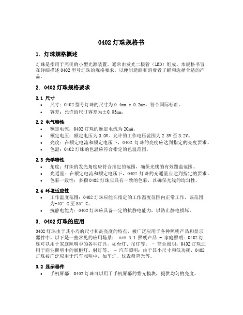
0402灯珠规格书1. 灯珠规格概述灯珠是指用于照明的小型光源装置,通常由发光二极管(LED)组成。
本规格书旨在详细描述0402型号灯珠的规格要求,以便制造商和消费者了解和选择合适的产品。
2. 0402灯珠规格要求2.1 尺寸•尺寸:0402型号灯珠的尺寸为0.4mm x 0.2mm,符合国际标准。
•容差:允许的尺寸容差为±0.05mm。
2.2 电气特性•额定电流:0402灯珠的额定电流为20mA。
•额定电压:额定电压为3.0V,允许的工作电压范围为2.8V至3.2V。
•亮度:在额定电流和额定电压下,0402灯珠的亮度应达到指定的亮度要求。
•色温:0402灯珠的色温应符合指定的色温范围。
2.3 光学特性•角度:灯珠的发光角度应符合指定的范围,确保光线的有效覆盖范围。
•光通量:在额定电流和额定电压下,0402灯珠的光通量应达到指定的要求。
•色彩一致性:多颗0402灯珠应具有一致的色彩,以确保光线的均匀性。
2.4 环境适应性•工作温度范围:0402灯珠应能在指定的工作温度范围内正常工作,该范围为-40°C至85°C。
•抗静电能力:0402灯珠应具备一定的抗静电能力,以防止静电损坏。
3. 0402灯珠的应用0402灯珠由于其小巧的尺寸和高亮度的特点,被广泛应用于各种照明产品和显示器件中。
以下是一些常见的应用场景: ### 3.1 照明产品 - 家庭照明:0402灯珠可以用于家庭照明中的各种灯具,如台灯、吊灯等。
- 商业照明:0402灯珠适用于商业照明中的展柜灯、射灯等。
- 汽车照明:由于其小尺寸和低功耗,0402灯珠被广泛应用于汽车照明中,如车灯、仪表盘背光等。
3.2 显示器件•手机屏幕:0402灯珠可以用于手机屏幕的背光模块,提供均匀的亮度。
•平板电脑:0402灯珠也可以用于平板电脑的背光模块,确保屏幕显示效果良好。
•智能穿戴设备:由于0402灯珠的小尺寸,它们可以被集成到智能穿戴设备中,提供指示灯、显示等功能。
LC8812B-5050RGBW规格书
ELECTROSTAICSENSITIVE DEVICES制作核准接受不接受6.RGBW芯片特性参数Ta=25℃:TOHTOLT1HT1LTreset0码1码Reset 码DIN DO PIX1DINDOPIX2D1D2D3D4DINDOPIX3注:其中复位码>=80us数据刷新周期表1复位码D1D2D3D4注:高位先发,按照GRBW 的顺序发送数据(G7→G6→ 005V1045V104U1U25V104U3RR辐射图特性曲线17.包装规格:载带规格(单位:mm)卷轴尺寸:防潮带包装:标签描述:PRODUCT NO:产品型号QUANTITY:包装数量LOT NO:指令单号CCT:色温BIN:色区代码Ra:显数指数DATE:生产日期注明:SMD5050系列包装标准1000PCS/包,特别要求除外。
标签示图贴标签位贴标签位注:标注公差为±0.1mm,单位:mmPRODUCT NO:QUANTITY:PCSLOT NO:DATE:Lead freePRODUCT NO:产品型号QUANTITY:包装数量LOT NO:指令单号DATE:生产日期1.6.已完成装配的灯珠元件进行防潮管控对需要进行二次SMT工艺或高温的产品,在完成一次焊接后将会进行二次焊接前,亦应做好必要的防潮处理,暴露在(≦30℃/60%RH)条件下,最长不能超过2H,若二次高温生产相隔时间较长,则一次焊接后的材料必需进行必要的除湿工作(在70℃±5℃的烤箱中烘烤不少于12小时),然后抽真空密封保存,或者先将产品储存在干燥箱恒温恒湿箱内,二次高温生产前,再做进行除湿工作(在70℃±5℃的烤箱中烘烤不少于12小时),以确保产品在过高温工艺前不受潮,低湿烘烤条件:70℃±5℃烘烤不小于12小时高温烘烤条件:130°C±5°C烘烤5小时,回流焊正常作业累计不超过3次,对挤出工艺或者高温防护处理的产品,建议产品做防护工艺前,做好必要的除湿工作,在130℃±5℃的烤箱中烘烤5小时,以剔除产品在检测,老化,运输过程中暴露在空气中吸收的湿气,以避免产品在做防护处理后,包在材料表面的湿气会慢慢侵入材料,造成产品失效,1.7.回流焊焊接经丽创光电采用下面所列参数检测证明,表面贴装型LED符合JEDEC J-STD-020C标准。
LC8805B-1515RGB规格书
ELECTROSTAICSENSITIVE DEVICES制作核准接受不接受备注:所有尺寸标注单位为毫米公差为±0.1毫米,除特别标注外。
引脚主数据输入控制数据信号输入脚供电电源正端主数据输出控制数据信号输出脚地线或电源负端13.数据结构(Ta=25℃):TOHTOLT1HT1LTreset0码1码Reset 码DIN DO PIX1DINDOPIX2D1D2D3D4DINDOPIX3注:其中复位码>=80us数据刷新周期表1复位码D1D2D3D4注:高位先发,按照GRB 的顺序发送数据(G7→G6→ 005V1045V104U1U25V104U3RRRelative spectral emission相对光谱分辐射图特性曲线16.包装规格:载带规格(单位:mm)卷轴尺寸:防潮带包装:标签描述:PRODUCT NO:产品型号QUANTITY:包装数量LOT NO:指令单号CCT:色温BIN:色区代码Ra:显数指数DATE:生产日期注明:SMD1515系列包装标准4000PCS/包,特别要求除外。
标签示图贴标签位贴标签位注:标注公差为±0.1mm,单位:mmPRODUCT NO:QUANTITY:PCSLOT NO:DATE:Lead freePRODUCT NO:产品型号QUANTITY:包装数量LOT NO:指令单号DATE:生产日期SMD 型LED 使用注意事项感谢您使用深圳市丽创光电有限公司的系列LED 产品,为增进您对我司产品特性的了解,也为方便您快速掌握产品的基本操作,为尽量减少或避免因人为等因素造成不必要的产品损坏,使其能够更好的为您的生产服务,特针对使用过程中的一些规范使用作相应说明,同时即使是同一规格LED,在实际应用领域其可靠性与设计水平,作业方式,使用条件均相关,本使用说明不能涵盖客户使用过程中可能碰到的所有问题,由此带来的不便,敬请谅解!1.1.通常LED 也象其它的电子元件一样有着相同的使用方法,为一让客户更好地使用丽创光电的LED 产品,请参看下面的LED 保护预防措施。
byk标准光源灯箱技术规格书

byk标准光源灯箱技术规格书一、产品概述BYK标准光源灯箱是一种专业的光源设备,用于提供标准化的光照环境,广泛应用于色彩检测、色差评价以及光学材料研究等领域。
本技术规格书旨在对BYK标准光源灯箱的技术参数和使用方法进行详细说明。
二、技术参数1.光源种类:BYK标准光源灯箱采用了多种光源,其中包括D65、D50、TL84、CWF、A等光源。
2.光源亮度调节范围:通过控制设备面板上的亮度控制旋钮,可以实现对光源亮度的精确调节,范围为0-100%。
3.色温范围:BYK标准光源灯箱的色温范围为5000K-7500K,可根据实际需求进行调整。
4.光源均匀度:灯箱内配备了均匀性优异的反射镜和光源布局,可以保证光源的均匀性,均匀度在±2%以内。
5.光源寿命:每个光源的寿命为2000小时以上,具有较长的使用寿命。
6.灯箱尺寸:BYK标准光源灯箱的尺寸为1200mm*700mm*200mm,可以容纳多个样品进行同时检测。
三、产品特点1.高光源稳定性:BYK标准光源灯箱内部采用了先进的光源驱动技术,可以保证光源的稳定性,避免光源闪烁或不稳定的问题。
2.色彩还原度高:灯箱内的光源经过精确调校,可以提供高度一致的色彩还原度,有效保证色彩的准确性。
3.操作简便:设备面板操作简单易懂,提供明确的调节按钮和显示屏,用户可以根据实际需求进行相应的调节。
4.多种光源选择:灯箱提供多种不同光源可选,可以满足不同行业的检测需求。
5.多样化检测模式:支持多种不同的检测模式,包括单一光源照明模式、多种光源混合照明模式以及闪光照明模式等,满足不同检测需求。
6.具备数据记录功能:灯箱内部具备数据记录功能,可以记录每次使用的光源、亮度等参数,方便后续的数据分析和验证。
四、使用方法1.将需要检测的样品放置在灯箱内,确保样品与光源的距离适当。
2.打开灯箱电源,选择所需的光源类型,并调节亮度。
3.根据实际需求,选择相应的照明模式,进行检测。
- 1、下载文档前请自行甄别文档内容的完整性,平台不提供额外的编辑、内容补充、找答案等附加服务。
- 2、"仅部分预览"的文档,不可在线预览部分如存在完整性等问题,可反馈申请退款(可完整预览的文档不适用该条件!)。
- 3、如文档侵犯您的权益,请联系客服反馈,我们会尽快为您处理(人工客服工作时间:9:00-18:30)。
LED光源
各规格LED光源参数表Array 2
3
:81W 支架((1024支架¢¢5mm )
3W 、5W 支架((3501方形;外形尺寸:8×9mm )
3W 、5W 支架((3501圆形¢10mm ;厚度::2.5mm )
LED 光源
15.515.5×
×22.522.5×
×LED 光源
10W-20W 支架架(3501K 圆形¢13.5mm ;厚度::2.5mm)
10W-20W 支架((5151椭圆形;外形尺寸::15.515.5××22.5mm;定位孔::19mm )10W-20W 支架((3005支架;外形尺寸::20202020××20mm;定位孔::18181818×
×18mm )10W-20W 支架((3004支架;外形尺寸::22.522.5××39mm ;定位孔::16161616××32mm )
LED光源
2626××38mm)30W-40W支架((5001支架;外形尺寸::2828
2828××40mm;定位尺寸::2626
2929××26mm)
3131××28mm;定位尺寸::2929
30W-40W支架((5001K支架;外形尺寸::3131
2020××20mm;定位尺寸::1818
1818××18mm)30-40W支架架(3003K支架;外形尺寸::2020
3434××34mm)
30W-200W支架架(5002支架;外形尺寸::4040
4040××56mm;定位孔::3434
LED光源
4040××46mm;定位孔::3434
3434××34mm) 30W-200W支架架(5003支架;外形尺寸::4040
3232××34mm)
4040××46mm;定位孔::3232
30W-200W支架架(5004支架;外形尺寸::4040
80W光源((5006支架高电压240V)
5009支架,定位孔34*34mm 或34*32mm ,外形尺寸40*46mm
5008支架
5030支架,,60*6260*62mm
mm LED 光源
0155(椭圆形)(10W-20W 支架)外形尺寸:27.5×21mm 定位孔距24mm 厚度 3.5mm。